Category HIGHWAY ENGINEERING HANDBOOK

Loads

Introduction. Loads acting on buried structures include the dead load of the struc­ture itself, the dead load of the earth cover over the structure, the weight of the fluid within the structure, live loads from vehicles, and, under certain circumstances, exter­nal hydrostatic pressure from groundwater.

The structure dead load is only significant for rigid structures. Flexible structures are manufactured from plastic or metal. In each case, the weight of the material is insignificant when compared with the total load on the structure. For rigid structures, however, because the material is generally concrete and because the pipe wall thick­ness is considerable, the weight of the material should be included in the determination of the total load applied on the structure. For concrete pipe, the pipe weight, Wp, can be estimated using the following equations:

Circular:

Подпись: (5.23a)Подпись: (5.23b)Подпись: (5.23c)Wp = 3.3h (Di + h) in U. S. Customary units Wp = 74 X 10-6h (Di + h) for SI units

Arch or horizontal elliptical:

Wp = 2.8h (Si + h) in U. S. Customary units Wp = 63 X 10-6h (Si + h) for SI units

Vertical elliptical:

Wp = 4.2h (Si + h) in U. S. Customary units Wp = 94 X 10-6h (Si + h) for SI units

where Wp = pipe weight, lb/ft (kN/m)

Di = inside pipe diameter, in (mm)

Si = inside horizontal span, in (mm) h = pipe wall thickness, in (mm)

(See Concrete Pipe Technology Handbook, American Concrete Pipe Association, 1994.)

Earth Load. The first detailed studies of the loads on buried pipes were conducted by Anson Marston at the Iowa State University in the early 1990s. These studies resulted in the Marston load theory for rigid pipes. The theory provides a methodology for determining the loads on buried pipes in almost any installation condition.

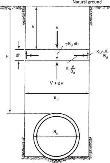
Marston theorized that a pipe in a trench was in static equilibrium. Therefore, the summation of vertical forces was zero. He also concluded that the pipe and backfill would settle relative to the in situ trench walls. He then went about determining the different forces acting on the pipe. Represented pictorially in Fig. 5.31, these are the weight of the soil in the trench, the resisting vertical force at the bottom of the trench, and the shear forces present at the interface of the backfill and the native trench wall.

Loads

FIGURE 5.31 Forces acting on a buried pipe as presented by Marston. (From Soil Engineering, 4th ed., HarperCollins, 1982, with permission)

Through a mathematical transformation of the equilibrium equation, Marston arrived at the following equation for a rigid pipe in a trench:

W£ = CdlBl (5.24)

with

Подпись: (5.25)Cd =

d 2Kp

where WE = earth load, lb/ft (kN/m)

7 = soil unit weight, lb/ft3 (kN/m3)

H = height of cover, ft (m)

Kp! = frictional coefficient
Bd = trench width, ft (m)

Marston also investigated the loads on rigid pipes in embankment conditions. However, since there are no trench walls, it was necessary to determine the relative movement of the pipe and soil directly above the pipe to the fill material adjacent to the pipe. The soil directly above the pipe is called the soil prism (see Fig. 5.32). This gave a measurement of the shear forces at the interface of the embankment and soil prism. Marston then used similar procedures for determining the loads on pipes in embankments as he used for pipes in trenches. He set the system in static equilibrium and summed vertical forces. Using this procedure, he derived formulas for several embankment installation conditions.
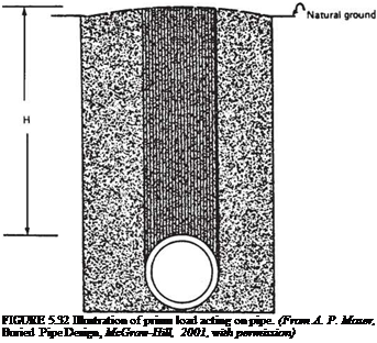
Подпись: FIGURE 5.32 Illustration of prism load acting on pipe. (From A. P. Moser, Buried Pipe Design, McGraw-Hill, 2001, with permission)

Marston’s student, M. G. Spangler, expanded the previous work of Marston in determining a method for relating the strength of an installed rigid pipe to the strength

of a pipe in a three-edge bearing test. Marston originally introduced the concept of a bedding factor for this purpose. Spangler refined the method by introducing the 0.01-in (2.5-mm) crack as a laboratory performance limit for equating the in-field perfor­mance to the three-edge bearing test performance. Later, as use of corrugated metal pipe increased, Spangler noticed that the Marston load theory did not provide satisfac­tory results for flexible pipes. The load that a flexible pipe was able to support was much greater than what was predicted using Marston load theory and bedding factors. Spangler completed a series of field and laboratory tests to investigate the loads on flexible pipes. His analyses resulted in the now famous Iowa formula, which was sub­sequently revised by R. K. Watkins.

More recently engineers have attempted, through the use of computers and finite element analysis, to better represent soil-structure interaction and the resultant loads on buried pipes. They have met with varying degrees of success. The works of both Marston and Spangler are still widely used in engineering practice. The calculation of pipe deflection by the Iowa formula is given in Art. 5.8.6. For a complete discussion of the Marston load theory and Spangler’s Iowa formula, see A. P. Moser’s Buried Pipe Design, 2d ed., McGraw-Hill, 2001.

Loads Подпись: D Подпись: (5.26)

Representations of earth loads are gradually moving away from the use of the Marston loads. In lieu of the Marston loads, the earth load is represented as a proportion of the soil prism load. The soil prism load is the weight of the column of soil directly above the pipe:

where Wc = prism load, lb/ft (kN/m)

у = soil unit weight, lb/ft3 (kN/m3)

H = height of cover, ft (m)

Do = outside pipe diameter, ft (m)

This is depicted graphically in Fig. 5.32. Depending upon the pipe type (stiffness) and the relative quality of the soil envelope, the effective earth load on the pipe may be greater than, equal to, or less than the soil prism load. This modification of the soil prism load is made via an arching factor. Therefore, the total vertical earth load acting on the structure, WE, is

Подпись: (5.27)W£ = VAF (Wc)

where Wc = prism load

VAF = vertical arching factor

Live Load and Impact. Culverts are usually designed for the live load generated by an AASHTO HS 20 truck. The controlling loading for culverts consists of two axles spaced 14 ft (4.3 m) apart, each weighing 32 kip (145 kN), with wheels on the axle spaced 6 ft (1.8 m) apart transversely. The 16-kip (73-kN) wheel load is the same as for an H 20 load­ing. The live load applied to underground structures under load factor criteria is either a standard HS truck, or a live load lane.

Where the culvert has a span of 20 ft (6.1 m) or greater, it is classified as a bridge and must be investigated for an alternate military loading of two axles 4 ft (1200 mm) apart with each axle weighing 24 kip (107 kN). The live load lane consists of a uniform load applied in conjunction with a concentrated load. The concentrated load is distrib­uted across the design lane of 10 ft (3000 mm), and is the uniform load. Because of this and because of the relatively short spans associated with culverts, the standard HS truck usually controls as the critical loading.

Loads

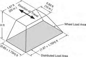
FIGURE 5.33 Distributed load area for single dual wheel. Conversions: 1 in = 25.4 mm, 1 ft = 0.305 m. (From Concrete Pipe Design Manual, American Concrete Pipe Association, 2007, with permission. )

Where the fill over a culvert is 2 ft (600 mm) or more, the wheel live load of 16 kip (73 kN) is applied as a concentrated load acting on the wheel print area and uniformly distributed over a rectangle with sides increasing at a rate of 13/4 times the depth of cover. This is represented pictorially in Fig. 5.33. If areas from several concentrated loads overlap, the total load is uniformly distributed over an area as defined by the outside limits of the individual areas.

Rigid structures with less than 2 ft (600 mm) of cover use a different method for dis­tributing the live load. AASHTO code requires that in this case the live load be distributed using the same method as is used in distributing live load in a concrete slab. This method is generally only applied to reinforced concrete box culverts or three-sided culverts.

An impact factor is added to the highway live loading. The factor is equal to 30 percent of the live load for a soil cover of 1 ft (300 mm) or less and decreases to 20 percent for a cover up to 2 ft (600 mm) and to 10 percent for a cover up to 2 ft 11 in (875 mm). There is no impact applied when the cover is equal to or greater than 3 ft (900 mm).

STRUCTURAL DESIGN OF DRAINAGE PIPES

5.8.1 General Considerations

The structural capacity of an underground structure and the methods of determining that capacity are dependent upon the material properties of the structure and its physical configuration. In this context, the structure is the composite structure comprised of the pipe and the surrounding soil. The surrounding soil is generally referred to as the soil envelope, and buried structures rely upon the soil envelope for their ability to with­stand loads.

Under load, the pipe will deflect laterally and mobilize the passive resistance of the surrounding soil. Also, the pipe and surrounding soil will settle and the pipe will deflect to varying degrees. The relative movement of the pipe and soil results in the stiffer component attracting load and the less stiff component shedding load. This phe­nomenon is called soil-arching and is a fundamental consideration in the pipe-soil system. A study of the soil-structure interaction is necessary for an adequate solution to the buried structure problem.

Pipes are generally classified as either rigid or flexible, depending on their bending stiffness. For a round pipe under load without the benefit of the soil envelope, deflec­tion due to bending is proportional to D^/EI, where D is the diameter, E is the modulus of elasticity, and I is the moment of inertia of the wall cross-section. EI is the wall­bending stiffness. Concrete and clay pipe usually have a relatively thick wall and a high bending stiffness, and are referred to as rigid pipe. Corrugated metal pipe and plastic pipe have much thinner walls and lower bending stiffness, and are referred to as flexible pipe. Any discussion of the structural capacity of the pipe must also discuss whether the pipe is flexible or rigid (these are the only two options), since the design methods for each vary significantly.

Rigid pipe, unless designed by the empirical D-load method, is designed for moment, thrust, and shear. Corrugated metal pipes can generally be designed for thrust alone. Plastic pipes are designed for thrust, deflection, and bending stress and strain.

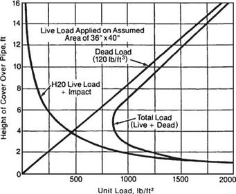
The combination of dead and live loads causes variable pressures on the installed pipe. As illustrated in Fig. 5.29, the dead load pressure increases with an increase in cover height, whereas the live load decreases with an increase in cover height. For highway loads, this results in a minimum load on the structure when there is approxi­mately 4 to 5 ft (1.22 to 1.52 m) of cover. Standard designs for underground structures may be found in industry publications with minimum and maximum cover heights indi­cated. However, when a structure is designed for a site-specific cover height, the designer should be aware that future changes in roadway elevation may cause increased loading conditions.

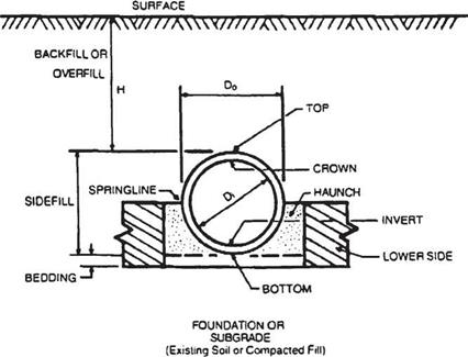
Figure 5.30 shows the nomenclature generally used for culvert design and installa­tion. The supporting soil beneath the culvert is the foundation, and the bedding is that

STRUCTURAL DESIGN OF DRAINAGE PIPES

FIGURE 5.29 Design pressures for metal culverts under earth dead load and

H 20 highway live load. Conversions: 1 ft = 0.305 m, 1 lb/ft2 = 0.0479 kPa. (From Handbook of Steel Drainage and Highway Construction Products, American Iron and Steel Institute, 1994, with permission)

STRUCTURAL DESIGN OF DRAINAGE PIPES

FIGURE 5.30 Pipe installation terminology. (From Design Data 40, American Concrete Pipe Association, 1992, with permission)

portion of the foundation in contact with the bottom of the pipe. The springline of the pipe is located at the location of maximum span. For a circular or elliptical pipe, this occurs at midheight. The haunch is the zone between the springline and the invert. The soil placed and compacted around the culvert is known as the backfill, or sometimes as the sidefill. The bedding and backfill are collectively referred to as the embedment.

In 1997 AASHTO published the first edition of the LRFD Bridge Design Specifications, and in 2007 the fourth edition. The goal of AASHTO is to use only the LRFD design code for new construction. However, the more traditional methods are currently more widely used for pipe design.

Guidelines for Culvert Selection

The following general guidelines from the Federal Lands Highway (FLH) manual should assist in determining appropriate culvert material types and necessary coatings. Other methods are available. Many state departments of transportation and local governmental agencies have published durability criteria, and this information should be used where available. A materials engineer should be consulted for important applications. Of course, the final selection must provide for structural requirements as discussed in Art. 5.8.

Concrete Pipe. Where the pH is less than 3.0 and the resistivity is less than 300 U • cm, reinforced concrete pipe should not be specified. If the sulfate concentration exceeds 0.2 percent in the soil or water, type V cement should be specified. If the sulfate con­centration exceeds 1.5 percent in the soil or water, an increased cement ratio using type V cement should be specified. The concrete cover over the reinforcement or the cement factor should be increased where there is severe abrasion.

Table 5.11 gives the minimum water side pH permitted for a concrete pipe culvert to obtain either a 50- or 75-year design service life. The table is based on research con­ducted by the Ohio Department of Transportation. Pipe size, barrel slope, and water side pH are statistically significant variables. It is interesting to note that the Ohio study found resistivity to not be a statistically significant variable.

Steel Pipe. Figure 5.28 shows a chart for determining the service life of a galvanized steel culvert under nonabrasive and low abrasive conditions. The average service life of

Minimum pH to attain
design service life*

TABLE 5.11 Requirements for Concrete Pipe Protection

Pipe slope

Pipe rise, in

Pipe rise, mm

50 yr

75 yr

Less

<42

<1050

3.0

3.3

than 1%

42-72

1050-1800

3.8

4.1

>72

> 1800

4.2

4.5

1-3%

<42

<1050

3.2

3.5

42-72

1050-1800

4.1

4.4

>72

> 1800

4.6

5.0

3-10%

<42

<1050

3.6

3.9

42-72

1050-1800

4.5

4.9

>72

> 1800

5.0

5.4

Greater

<42

<1050

4.0

4.5

than 10%

42-72

1050-1800

5.0

5.5

>72

> 1800

5.5

6.0

*Based on Eq. (4) from Transportation Research Record 1008 Article “Field Performance of Concrete Pipe Culverts at Acidic Flow Sites in Ohio.” For stream flow with a pH less than the minimums listed above, epoxy-coated concrete pipe is required.

Source: From Location and Design Manual, Vol. 2: Drainage Design, Ohio Department of Transportation, with permission.

Подпись: 416Guidelines for Culvert Selection

Specified thickness, in (mm)

0.052 (1.32)

0.064 (1.63)

0.079 (2.01)

0.109 (2.77)

0.138 (3.51)

0.168 (4.27)

Factor

0.8

1.0

1.2

1.7

2.2

2.6

(b)

FIGURE 5.28 Method for estimating service life of plain galvanized steel culverts, (a) Service life chart for 0.064-in (1.63 mm) thickness based on invert performance, (b) Conversion factors for other thicknesses. (From Project Development and Design Manual, FHWA, with permission)

culvert with a wall thickness of 0.064 in (1.62 mm) is displayed in terms of pH and resistivity in Fig. 5.28a. For culverts with other wall thicknesses, obtain the service life from the chart and multiply by the factors in Fig. 5.28b. Use the chart for both the out­side conditions and the inside (water side) conditions and base the design on the worst case. Generally, the inside condition controls.

For steel with a type 2 aluminum coating, the FLH manual assigns a greater service life under certain conditions. For nonabrasive and low abrasive flow, where the resis­tivity is equal to or greater than 1500 П • cm and the pH is between 5 and 9, alu­minized steel is considered to provide a service life twice that of galvanized steel as determined from Fig. 5.28.

Protective Coatings on Steel Pipe. Under nonabrasive and low abrasive conditions, the service life of galvanized steel culvert can be extended by application of protective coatings. For example, when the water side environment controls the pipe thickness, application of an asphaltic coating (a postfabrication coating by the pipe manufacturer) can add 10 years of service life to the culvert, and an application of an asphaltic paved invert in addition to the coating will add a total of 25 years. If the soil side controls, application of the asphaltic coating will add 25 years of life. Concrete lining will add 25 years of service life. Ethylene acrylic acid film coatings (a polymer precoat on the galvanized coil) with a 10-mil (0.25-mm) thickness can be expected to provide an additional 30 years of service life. Currently, there are insufficient data to predict the performance of ploymer precoated pipe under severely abrasive conditions. Concrete pavings can be designed to add service life.

Aluminum Pipe. Under nonabrasive and low abrasive conditions, where the resistiv­ity is equal to or greater than 500 H • cm and the pH is between 4 and 9, aluminum culverts can be assumed to have a service life of 50 years when the metal thickness is appropriately sized for structural adequacy.

Design for Abrasion. In moderate abrasive environments, the sheet thickness for both steel and aluminum pipes should be increased by one nominal thickness, or the invert should be protected. In severe abrasive conditions, the sheet thickness should be increased by one nominal thickness and the invert should be protected. Invert protection under severe abrasive conditions may consist of metal rails or energy-dissipating devices at the inlet. Under moderate abrasive conditions, invert protection may consist of (1) paving with port­land cement concrete or (2) asphaltic coating and invert paving with bituminous concrete.

Plastic Pipe. Under most environmental and abrasive conditions, polyethylene and polyvinyl chloride plastic pipes may be specified without regard to the pH and resis­tivity of the site. Invert protection may be required under some abrasive conditions.

Example: Minimum Thickness of Galvanized Steel Culvert. The design service life for the culvert has been set at 50 years. A site investigation of a potential location shows that the soil has a pH of 7.2 and a resistivity of 5000 П • cm. The water flow shows a pH of 6.8 and a resistivity of 4000 П • cm. Determine the minimum sheet thickness for durability.

Outside condition. In Fig. 5.28a, find the intersection of the vertical line for

5000 П • cm with the inclined line for 7.2 pH, and read the average service life of

52 years from the vertical scale at the left.

Inside condition. In like manner, for a resistivity of 4000 П • cm and a pH of 6.8,

find the average service life of 42 years.

In this example, the inside conditions control the design, and the thickness must be increased. For the 0.064-in (1.63-mm) sheet thickness, the ratio of the design service life to the anticipated service life is 50/42 = 1.2. From Fig. 5.28b, the multiplying factor is 1.2 for a thickness of 0.079 in (2.01 mm). Therefore, a thickness of 0.079 in (2.01 mm) should provide the desired service life of 50 years.

An alternative is the application of an asphaltic coating, which can add 10 years of service life when the inside condition controls. For the 0.064-in (1.63-mm) sheet thickness, 42 + 10 = 52 years. Therefore, consider an 0.064-in (1.63-mm) sheet thickness with an asphaltic coating.

Abrasion

Abrasion causes a loss of section thickness due to impacts by the aggregate carried by stream flow. Protection from abrasion generally takes the form of providing a sacrifi­cial thickness of the structural material, whether it be a thicker sheet of steel or con­crete paved invert for metal pipe, or more concrete cover over the reinforcement for reinforced concrete pipe. Alternatives to providing for a thicker section include using debris control structures to prevent the abrasive material from reaching the culvert, and providing metal planking longitudinally along the invert as a separation between the bed load and the bottom of the culvert.

Abrasion can be considered in four levels of severity as categorized by streambed velocity and general aggregate size. Protective measures, particularly in the invert, should increase with increasing levels of abrasion as discussed subsequently. (See Project Development and Design Manual, Federal Lands Highway, FHWA.)

Level 1, termed nonabrasive, has very low flow velocities and no bed load.

Level 2, low abrasive, has flow velocities of 5 ft/s (1.5 m/s) or less and light bed load consisting of sand.

Level 3, moderately abrasive, has flow velocities of between 5 and 15 ft/s (1.5 and 4.5 m/s) and moderate bed loads consisting of sand and gravel.

Level 4, severely abrasive, has flow velocities exceeding 15 ft/s (4.5 m/s) and heavy bed loads consisting of sand, gravel, and rock.

The projected velocities should be based upon a typical flow and not upon the design flood for which the culvert has been designed. The bed load size may be determined by visual inspection of the surrounding environment and the upstream channel. Sampling of the aggregate for a gradation analysis is not necessary.

Environmental Factors

Important environmental factors that affect culvert durability include the acidity (pH) of the effluent and the soil, the electrical resistivity of the effluent and the soil, and the concentration of sulfates and chlorides. Data on these factors should be obtained at each pipe location, unless a random sampling plan is justified by establishing that the samples are uniform throughout a given length of the project. Water samples should be taken only during times of typical flows. If corrosive conditions are found to be present in the soil but not in the water samples, consideration should be given to using a better backfill material.

Concrete Pipe. Environmental factors that can affect the deterioration of concrete culverts include freeze-thaw, acids, sulfates, and chlorides. Freeze-thaw damage can occur if water penetrates the concrete interstices and then freezes and expands, causing cracking. Such damage would occur only at exposed ends of culverts, and low water – cement ratios or air entrainment can increase resistance. Continuous exposure to severe acidity is detrimental to concrete pipe; a pH below 5.0 is considered aggressive and below 4.0 highly aggressive. Improved resistance to acid attack can be attained by selecting aggregate that increases the total alkalinity of the concrete, increasing concrete cover over reinforcement, or adding barrier linings (e. g., epoxy coatings). Sulfates in the soil, groundwater, or effluent can be aggressive to concrete. Such problems, which are generally limited to arid regions with alkali soils, may be addressed with special cements and mix design. Chloride attack can potentially result from use of deicing salts and subsequent runoff.

Metal Pipe. Environmental factors that affect the corrosion of metal culverts include the acidity (pH) and the resistivity of the soil and water, and the moisture content, sol­uble salt content, oxygen content, and bacterial activity of the soil. These corrosion processes all involve the flow of current from one location to another. The current flows from an anodic area to a cathodic area through moist soil acting as an elec­trolyte, and this system is known as a corrosion cell. Thus, durability increases with increasing resistivity. Acid soils, those with low pH, tend to be more corrosive. Also, soils with high moisture content, such as loams and clays, tend to be more corrosive. High levels of chlorides and sulfates increase corrosion, as do increasing levels of dis­solved oxygen and carbon dioxide. Numerous field studies have shown that the culvert invert is the portion most susceptible to corrosion, because it is generally exposed to water for a greater length of time. Thus, design charts are usually based on service life observed in the invert.

Plastic Pipe. PE and PVC pipe are not affected by acid conditions, or by sulfates or other alkalis. These materials can become embrittled from ultraviolet radiation as a result of prolonged exposure to direct sunlight, such as at culvert ends, but inhibitors are added to the composition of the material to substantially reduce this effect. If problems are encountered, ends can be shaded, covered with a coupling, or painted.

CULVERT SERVICE LIFE

The prediction of service life of drainage facilities is difficult because of the wide range of environments encountered and the various protective measures available. Service life and durability are directly related to resistance to corrosion, abrasion, and other modes of deterioration.

5.7.1 Design Service Life

Drainage facilities are usually designed for a specific service life. The design service life is sometimes defined as the expected period for which they are relatively free from maintenance. However, it can be defined to include a planned rehabilitation after a given number of years to reach the required service life as part of a value analysis approach. (See Art. 10.10.1.)

For a metal culvert, the design service life can be based on the number of years between the time it is installed and the time a perforation from either corrosion or abrasion occurs at any location in the culvert. However, this is a rather conservative approach because the consequences of small perforations are usually minimal and a single perforation can occur long before there is a general thinning of the metal. Thus, service life charts are often based on an average service life that extends life past first perforation by 25 percent or more. For a concrete culvert, the design service life is usually defined as the time between installation and when deterioration reaches the point of exposed reinforcement anywhere in the culvert.

The selection of design service life is dependent upon the use, importance, and ease of replacement of the culvert. A culvert located under a high fill or a roadway with high traffic volumes will be expensive to replace, and the replacement will disrupt traffic. Thus, such culverts are often assigned a design service life of 50 years or more. In contrast, a culvert parallel to the main road—for example, a pipe underneath an access road—will be relatively easy to replace and can be replaced with little disruption. Thus, such culverts, including those under low fill or on a minor roadway, are often assigned a shorter service life.

Steel and Aluminum Pipe

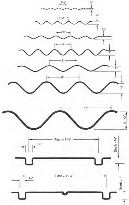
Numerous drainage products are available in steel with protective coatings and in aluminum. These include corrugated pipe, spiral-rib pipe, structural-plate pipe, box cul­verts, and, where a tunnel is required, tunnel liner plates. Figure 5.24 shows the variety of profiles available for the wall cross-section of steel drainage products. For additional profiles, see “Corrugated Steel Pipe Design Manual,” National Corrugated Steel Pipe Association, 2008. The arc-and-tangent profiles shown with depths of through 1 in (6.5 through 25 mm) are wall profiles for pipe factory-corrugated to the full pipe

Steel and Aluminum Pipe

FIGURE 5.23 Cross-section of cast-in-place con­crete pipe showing form components. (From Lynch Manual, Cast-in-Place Concrete Process, W. M. Lynch Co., Dixon, Calif., 1990, with permission)

cross-section. The 2-in-deep (51-mm) profile, which is used for structural-plate pipe and box culverts, is corrugated and curved into arc segments that can be bolted together in the field. The 552-in-deep (140-mm) profile is a similar product used for longer-span structures. The 54- and 1-in-deep (19- and 25-mm) rectangular profiles are for factory-corrugated spiral-rib pipe. Figure 5.25 illustrates the shapes of the products, the range of sizes available in steel, and common uses. Some corrugation profiles and size ranges vary for aluminum products. The larger sizes of structural-plate products and box culverts in steel or aluminum are often used as replacements for short-span bridges. Factory-made box culverts are available in spans up to 26 ft (7.8 m) and even longer with special designs.

Corrugated Steel. Most of the metal pipes used are corrugated from coils of coated sheet steel. Coatings, which are applied by the continuous hot-dip process in the production of the steel coil, include zinc (galvanizing) and aluminum. In addition, coils are available precoated with a polymer (on one or both sides) to provide extra protection against corrosion and/or abrasion. Most corrugated pipes have a continuous helical lockseam, but some manufacturers use a continuous helical welded seam, or a longitudinal riveted or spot-welded seam. Wall profiles from 1/2 X ^4 in (38 X 6.5 mm) to 5 X 1 in (125 X 25 mm) are factory-corrugated to the full pipe cross-section. The pipe is furnished in lengths (typically 20 ft or 6 m) and joined in the field by coupling bands. Diameters through 120 in (3000 mm) are available, depending on the wall profile. Pipe-arch shapes for installations with low cover are formed to shape from lengths of round pipe.

Corrugated Aluminum. Corrugated aluminum pipe is usually furnished with one of the following wall profiles: 152 X 34 in (38 X 6.5 mm), 253 X 52 in (68 X 13 mm), or 3 X 1 in (75 X 25 mm). The pipe may have a helical lockseam or a riveted seam. It is furnished in lengths similar to steel pipe and joined in the field by coupling bands. Diameters through 120 in (3000 mm) are available, depending on the wall profile, and pipe-arch shapes are formed to shape from lengths of round pipe.

Spiral-Rib Pipe. This is a newer type of steel pipe that is helically corrugated to the rectangular profiles shown in Fig. 5.24. The cross-section profile has been developed so

Steel and Aluminum Pipe

FIGURE 5.24 Profiles for corrugated steel pipe and spiral-rib pipe. Conversion: 1 in = 25.4 mm. (From Handbook of Steel Drainage and Highway Construction Products, American Iron and Steel Institute, 1994, with permission)

Shape

Range of Sizes

Common Uses

Round

©

6 in.-26 ft (150 mm-7.9 m)

Culverts, subdrains, sewers, service tunnels, etc. All plates same radius. For medium and high fills (or trenches).

Vertical ellipse 5% nominal

0

4-21 ft (1.2-6.4 m) nominal: before elongating

Culverts, sewers, service tunnels, re­covery tunnels Plates of varying radii, shop fabrication. For appearance and where backfill compaction is only moderate

Pipe-arch

Span

~T

Rise

LL

Span x Rise 17 in. x 13 in. (430 x 330 mm) to

20 ft 7 in. x 13 ft 2 in.

(6270 x 4010 mm)

Where headroom is limited. Has hydraulic advantages at low flows. Corner plate radius, 18 in (457 mm) or 31 in (787 mm) for structural plate.

Underpass’

P

l-Span-n

1

Rise

*

Span » Rise 5 ft 8 in x 5 ft 9 in­to

20 ft 4 in x 17 ft 9 in.

For pedestrians, livestock or vehicles (structural plate)

. . Rise Arch ( Г

1-—Span -|

Span x Rise 6 ft x 1 ft 91/2 in. (1.8 x 0.55 m) to

25 ft x 12 ft 6 in. (7.6 x 3.8 m)

For low clearance large waterway open­ing. and aesthetics (structural olate)

Horizontal / Ellipse P

— Span—>

Span 7-40 ft (2.1-12 m)

Culverts, grade separations, storm sewers, tunnels.

Pear

0 —Span —

Span 25-30 ft (7.6-9.1 m)

Grade separations, culverts, storm sewers, tunnels.

High Profile i Arch

______________ l

— Span —-

Span 20-45 ft (6.1-14 m)

Culverts, grade separations storm sewers, tunnels Ammunition magazines, earth covered storage.

Low Profile / Arch 4

■ Span ■

|r

Span 20-50 ft

(6.1-15 m)

Low-Wide waterway enclosures, culverts, storm sewers.

Во» Culverts

cn

– Span —4

Span 8-26 ft (2.4-7.9 m)

Low-wide waterway enclosures, culverts, storm sewers

Specials

Various

For lining old structures or other special purposes. Special fabrication.

‘For equal area or clearance, the round snape is generally more economical and simpler to assemble

FIGURE 5.25 Shapes, range of sizes, and common uses of corrugated steel drainage products. Conversions: 1 in = 25.4 mm, 1 ft = 0.305 m. (From Handbook of Steel Drainage and Highway Construction Products, American Iron and Steel Institute, 1994, with permission)

that flow characteristics are similar to that of a smooth-walled pipe. It is available in either coated steel or aluminum, as either round pipe through 108-in (2700-mm) diameter, or as pipe-arch.

Structural-Plate Pipe. This product type is available in either zinc-coated steel or aluminum.

Steel. The 6- X 2-in (152- X 51-mm) profile used for structural-plate pipe and box culverts is corrugated and curved into arc segments. The segments provide an arc length of up to about 86 in (2184 mm), in lengths of 10 or 12 ft (3.0 to 3.7 m). The segments are joined together with high-strength bolts in a sequential manner during construction. All of the shapes illustrated in Fig. 5.25 can be constructed with this product. The 15- X 5L-in (381- X 140-mm) profile can be used for the larger struc­tures. With spans up to about 50 ft (15 m), structural-plate structures can provide an economical alternative for replacing short-span bridges. Field coatings can be applied to enhance durability.

Aluminum. The 9-in-wide (230-mm) by 2i2-in-deep (64-mm) profile is used for the aluminum structural-plate pipe and box culvert structures. Product characteristics are generally similar to those of the steel product.

Long-Span Structures. Long-span structural-plate structures are defined as having either special shapes that involve a relatively large radius in the crown or side plates, or a span that exceeds certain structural design criteria as specified in AASHTO Standard Specifications for Highway Bridges. These structures generally have spans in the range of 20 to 50 ft (6 to 15 m). They are advantageous where headroom is restricted and can often provide the required waterway area at a lower cost than building a short-span bridge. Long-span structures are made up of a structural-plate barrel of coated steel or aluminum and integral special features that enable the structure to reach long spans. Special features include either (1) continuous longitudinal stiffeners of metal and/or reinforced concrete attached to the plates at the sides of the top arc, or (2) circumferential reinforcing ribs curved from structural shapes and attached to the plates to provide additional stiffness. Typical sections of each are illustrated in Fig. 5.26. They may be constructed to most of the shapes shown in Fig. 5.25 except box culverts.

Box Culverts. This product type is available in either zinc-coated steel or aluminum.

Steel. Box culverts are available in three types, including (1) 6- X 2-in (152- X 51-mm) corrugated plate shell with 6- X 3-in (152- X 76-mm) corrugated rib stiffeners (inside, outside, or both), (2) 6- X 2-in (152- X 51-mm) corrugated plate shell with 3- X 5-in (76- X 127-mm) hot rolled angle rib stiffeners, and (3) 15- X 5.5-in (381- X 140-mm) corrugated plate shell without stiffeners. Sizes range as shown in Fig. 5.25. The structures usually have an open bottom and are supported on a base channel or corrugated footing pads, on either a concrete footing or compacted soil, depending on size and other factors. They are also available with full invert plates.

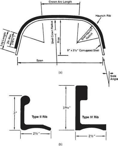
Aluminum. Box culverts have a 9- X 2i2-in (230- X 64-mm) corrugated shell plate with extruded bulb angle rib stiffeners. Size ranges are similar to those for steel box culverts. Figure 5.27 shows a typical section and rib cross-sections. Stronger ribs, including a box-section rib, are available.

Tunnel Liners. Tunnel liners are press-formed from steel in an arc segment 16 or 18 in (400 or 450 mm) long. A corrugated profile is pressed in to make the wall cross­section, and flanges are formed on the sides. Two styles are available: (1) two-flange plates that are bolted through the flanges on the two longitudinal sides and lap-bolted

Подпись: Symmetrical about £

Steel and Aluminum PipeConcrete Thrust Beam

Thrust Beam to be made integral with Headwall

Span

Подпись: Symmetrical about <£Structural member attached to structural

plate corrugation

Staggered joints except at radius change

Span

FIGURE 5.26 Typical sections of long-span structural-plate structures. (a) Longitudinally stiffened with concrete thrust beam. (b) Transversely stiffened with structural members. (From Highway Design Manual, California Department of Transportation, with permission)

on the other two sides, and (2) four-flange plates that are bolted together through flanges on all four sides. Installation and assembly can be done entirely from the inside as the tunnel is constructed. The assembled liner plates may then act as a tem­porary structure that is lined by concrete, or may act alone as a permanent conduit. In addition to tunneling, the liner plates can be used in rehabilitation work, such as for lining a deteriorated culvert.

Steel and Aluminum Pipe

FIGURE 5.27 Corrugated aluminum box culvert. (a) Typical cross-section. (b) Details of stiffen­ing ribs. Conversion: 1 in = 25.4 mm. (From Aluminum Box Culverts, Contech Construction Products, with permission)

5.6.2 Plastic Pipe

Both high-density polyethylene (HDPE) and polyvinyl chloride (PVC) are used for drainage pipe. HDPE pipe may be single-wall corrugated, smooth-wall (double-wall), or ribbed. Common diameters are 4 to 24 in (100 to 600 mm) for single wall, 4 to 60 in (100 to 1500 mm) for double wall, and 18 to 96 in (450 to 2400 mm) for ribbed pipe. Single-wall pipe has a deep corrugation, whereas a smooth internal liner is added for double­wall pipe. Wall profile details vary with the manufacturer. PVC pipe may be either smooth-wall or ribbed, with diameters ranging up to 54 in (1350 mm). Plastic pipe is fur­nished in lengths (typically about 20 ft (6 m) for HDPE and 13 ft (4 m) for PVC) and joined in the field by coupling bands. It is available only as round pipe.

CULVERT TYPES AND MATERIALS

The main types of pipe used in highway construction are concrete pipe, metal pipe (steel or aluminum), and plastic pipe (high-density polyethylene and polyvinyl chloride). They are available in a wide array of sizes, shapes, and properties. Table 5.10 gives the ASTM and AASHTO standards for the most common highway drainage pipes. Some of the characteristics of these pipes are reviewed below.

5.6.1 Concrete Pipe

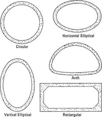
Concrete pipe is manufactured as nonreinforced, reinforced, or cast-in-place pipe; as box culverts and special shapes; and as field-constructed pipe. Shapes, as shown in Fig. 5.21, include round, horizontal and vertical ellipse, and arch configuration.

Factory-Made Pipe. Nonreinforced pipe is used for smaller diameters, whereas pipe with steel reinforcement is used for larger diameters and greater loads. Both are manu­factured in a plant, cured, and shipped to the job site. They are furnished in relatively short lengths and coupled with a bell-and-spigot or tongue-and-groove type joint.

Nonreinforced concrete pipe is available in diameters from 4 to 36 in (100 to 900 mm) and three strength classes. Nonreinforced concrete pipe is available as round pipe only. Reinforced concrete pipe is available in diameters from 12 to 144 in (300 to 3600 mm). The strength of reinforced concrete pipe can be specified according to five standard pipe classes (ASTM C 76), with Class I pipe being the most economical and Class V offering the greatest structural strength; according to required D-load strength (ASTM C 655); or according to a direct wall design (ASTM C 1417). Wall thickness of reinforced concrete pipe can be varied to meet in-field conditions. The standard “class” specifications for pipe give wall thickness according to three distinct types, which vary from Wall A, being the thinnest, to Wall C, being the thickest.

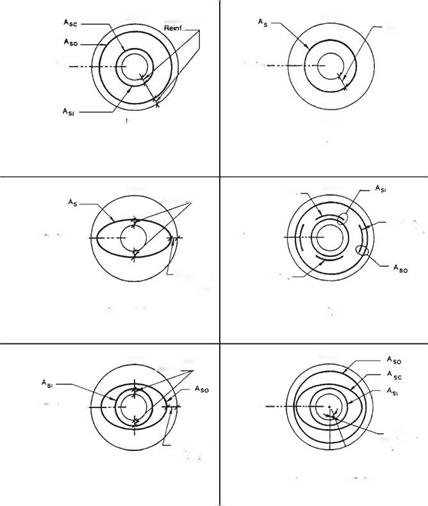
Steel reinforcing for reinforced concrete pipe can be arranged in many combina­tions to meet the given structural requirements. Figure 5.22 shows some of the steel reinforcement layouts used in manufacturing reinforced concrete pipe.

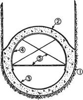
Cast-in-Place Pipe. This type of nonreinforced pipe is formed in a trench using a continuous process. First a trench is excavated so that it has a semicircular bottom and vertical or near vertical sidewalls, which serve as the outer form for the bottom and sides. The upper portion of the pipe is cast against an inner arch form as illustrated in Fig. 5.23. The form is pulled along the trench while concrete is poured into a hopper

TABLE 5.10 Standards for Common Drainage Pipes

Type of pipe

ASTM Standard

AASHTO Standard

Vitrified clay pipe

Vitrified clay pipe

C 700

M 65

Concrete pipe

Nonreinforced, circular

C 14, C 985

M 86

Reinforced, circular

C 76, C 655, C 1417

M 170

Reinforced, elliptical

C 507

M 207

Reinforced, arch

C 506

M 206

Reinforced, box

C 1433

M 259, M 273

Reinforced, three-sided

C 1504

Corrugated steel pipe

From metallic-coated sheet

A 760

M 36

From zinc-coated structural plate

A 761

M 167

From polymeric-coated sheet

A 762

M 245

Postmanufacture applied coatings

A 849, A 862

M 190

Box culverts

A 964

Corrugated aluminum pipe

From sheet

B 745

M 196

From structural plate

B 746

M 219

Box culverts

B 864

Plastic pipe

PVC (polyvinyl chloride)

D 1785

PVC

D 2665

PVC

D 3034

PVC

F 679

PVC

F 789

PVC

F 891

PVC

F 949

PVC

M 304

ABS PVC composite

D 2680

M 264

ABS (acrylonitrile-butadiene-styrene)

D 2661

ABS

D 2751

PE (polyethylene)

F 405

PE

F 667

PE

F 714

PE

F 892

PE

F 894

PE

M 252

PE

M 294

located above. Powered spading mechanisms and variable-speed vibrators aid the flow of the concrete.

Box Culverts. Box culverts are rectangular shapes with flat sides, top, and bottom. These shapes are constructed with steel reinforcement. Factory-made boxes are shipped in sections 4 to 8 ft (1200 to 2400 mm) long and joined in the field to make a structure of the required length.

Precast Three-Sided Culverts. Three-sided culverts, sometimes called “three-sided box culverts,” are rectangular in shape. These shapes are constructed with steel reinforcement

CULVERT TYPES AND MATERIALS

FIGURE 5.21 Concrete pipe is manufactured in five common shapes; regional custom and demand usually determine availability. (From Concrete Pipe Handbook, American Concrete Pipe Association, 1988, with permission)

that may or may not be pretensioned. They are available in spans between 12 and 34 ft (3.7 and 10.4 m), and rises up to 10 ft (3 m). These structures usually have an open bottom and are constructed on concrete footings.

Special Shapes. Other shapes are also manufactured. One example is a reinforced concrete section made up of an arch top and vertical sidewalls. Another example is a reinforced concrete arch that can be fabricated in either one or two piece segments. Both examples are joined in the field to make up the required length. With spans of 12 to 84 ft (3.7 to 25 m) or larger they are suitable as replacement structures for short span bridges. Additionally, segmental tunnel liners can be furnished as precast concrete segments.

Field-Constructed Pipe. Large reinforced structures may be constructed at the job site using appropriate formwork. Large arches and box culverts are often constructed in this manner.

Подпись: Double Circular Cage + Elliptical Cage

CULVERT TYPES AND MATERIALS CULVERT TYPES AND MATERIALS
Подпись: Crown
Подпись: Crown Cover over
Подпись: Cover over
Подпись: invert
Подпись: Invert
Подпись: Springiine
Подпись: Springiine
Подпись: Angle of

Подпись: Single Elliptical Cage

Подпись: Springiine
Подпись: invert Подпись: Invert

Подпись: Invert Mat Reinf

Подпись: Crown Cove( Qver Подпись: Crown CULVERT TYPES AND MATERIALS
CULVERT TYPES AND MATERIALS
Подпись: Single Circular Cage
Подпись: Crown
Подпись: Crown
Подпись: Springiine
Подпись: Cover over Reinf. __
Подпись: Springiine
Подпись: Springlme
CULVERT TYPES AND MATERIALS
Подпись: nvert
Подпись: Invert
Подпись: Crown Mat Reinf
Подпись: Springiine
Подпись: Springiine

CULVERT TYPES AND MATERIALSFIGURE 5.22 Concrete pipe culvert reinforcement notation. (From PIPECAR: User and Programmer Reference Manual, FHWA, 1989, with permission)
Discharge Velocity and Energy Dissipation

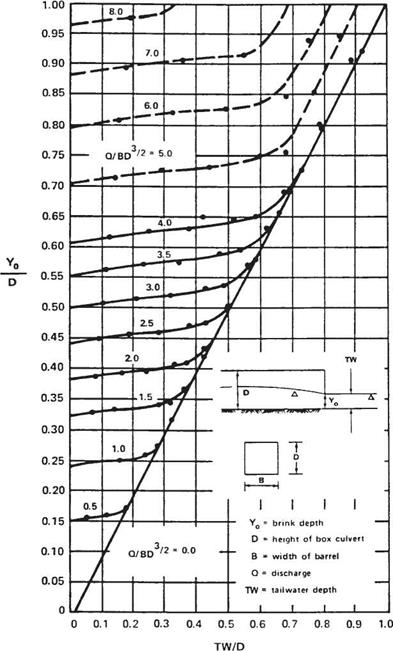
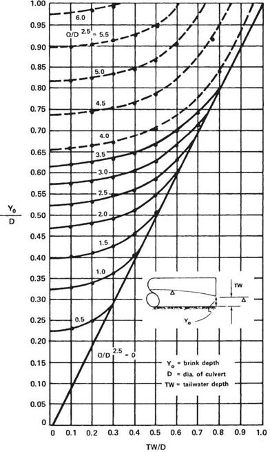
Because of its hydraulic characteristics, the outlet velocity of a culvert is usually higher than the velocity in the discharge channel. The outlet velocity may be calculated either using Manning’s equation, Eq. (5.11), if the culvert is under inlet control, or by divid­ing the discharge by the cross-sectional area of the flow if under outlet control. Under outlet control, if the tailwater is above the crown of the pipe, or if the discharge is high enough to result in a critical depth equal to the depth of the culvert barrel, then the flow area may be taken as the area of the barrel. If the tailwater depth is low, the area of flow, and thus the velocity, may be determined using the chart in Fig. 5.19 or 5.20. To use these charts, first calculate the normal depth or tailwater TW (ft) in the channel; the ratio TW/D, where D is the structure height (ft); and the flow parameter Q/BD3/2, where B (ft) is the width of the barrel and Q (ft3/s) is the discharge. Enter the chart with TW/D and find YJD at the intersection of the appropriate curve. Multiply by D to determine the depth of flow at the outlet end of the culvert, Yo. The flow area is then calculated for Yo and the velocity for the flow Q from the continuity equation, Eq. (5.10). o

Recommended maximum channel velocities were presented in Table 5.5. The velocity at the outlet should be kept at or below these values, or, if this is not possible, the channel should be protected from erosion. The controlling parameters for the cul­vert velocity are its slope and roughness. If the recommended velocity is exceeded, consider decreasing the slope or using a culvert with a greater roughness coefficient.

Discharge Velocity and Energy Dissipation

Discharge Velocity and Energy Dissipation

If the velocity at the outlet cannot be reduced by these means, channel protection or energy dissipaters should be used to protect against erosion. Channel protection may consist of treatments such as concrete aprons or cutoff walls. In some cases, concrete or rock riprap may be required. These types of protection do not necessarily dissipate the energy, but protect against erosion. Energy-dissipating devices may be necessary either separately or in conjunction with channel protection where flow velocities are high. Dissipation devices, if used, are generally located at the outlet end or in the inte­rior near the end of the culvert. If such devices are used, consideration must be given to the effects on possible debris collection. (See “Hydraulic Design of Energy Dissipators for Culverts and Channels,” HEC 14, FHWA.)

Size Determination for Long-Span Structures

Because culvert shapes are so numerous and new shapes are often developed, design charts showing performance curves are not available for all culvert sizes and shapes. One example is long-span corrugated-metal sectional plate structures. Although the product is available in several cross-sectional shapes, performance curves are avail­able only for circular or elliptical cross-sections (Fig. 5.17) and high – and low-profile arches (Fig. 5.18). These charts, which are for inlet control only, address four different inlet configurations ranging from mitered to beveled-edge ends. Because long-span structures are commonly used when headroom is low, they generally do not flow under head at design discharge but flow partly full.

The first step in using these charts is to obtain information on available sizes, including cross-sectional area A (ft2) and vertical height D (ft). For the design dis­charge Q (ft3/s), calculate Q/AD05 and read the value of HW/D at the intersection of the appropriate edge condition curve. Multiply by the depth (height) of the structure (D) to obtain the headwater depth HW and compare with the allowable design value. To consider a long-span structure under outlet control, an analysis including pressure flow and backwater calculation can be made. (See “Hydraulic Design of Highway Culverts,” HDS 5, FHWA.) The inlet and outlet control headwater elevations are then compared. The higher value is compared against the allowable elevation to determine if the size is satisfactory or if the process should be repeated.

Size Determination for Long-Span Structures

Size Determination for Long-Span Structures

FIGURE 5.18 Performance charts for high – and low-profile structural-plate arches under inlet flow control. (From “Hydraulic Design of Highway Culverts," Hydraulic Design Series No. 5, FHWA with permission)