Category HIGHWAY ENGINEERING HANDBOOK

Embankment Construction

Where a pipe is required as part of an embankment construction, it may be installed by compacting layers of fill uniformly on either side. It is important to bring the layers up uniformly on either side of the pipe. After a sufficient layer is compacted over the top of the pipe, ordinary embankment construction may proceed. Alternatively, some agencies require that the embankment be constructed first, then a trench dug for the installation of the pipe.

5.10.1 Trench Construction

The open-trench method is commonly used for culvert construction. It is more cost – effective than tunneling except when a pipe must be constructed in an existing high fill. Shoring may be necessary, particularly if the installation is under a traveled way. This will keep the limits of excavation to a minimum and, by the use of steel cover plates, allow the roadway to remain open during nonworking hours. Where it is necessary to use an open-trench method of construction in urban areas, it is wise for the designer to make available to the contractor options for the type of structure to be placed. For example, if a box culvert is deemed necessary by the engineer because of hydraulic considerations and physical constraints, a precast concrete or a prefabricated metal box, as alternatives to cast-in-place construction, should be permitted. In this manner, the traveling public expe­riences a minimum of disruption of service when open-trench construction is used. AASHTO recommends a trench width equal to 1.25 times the outside diameter of the pipe plus 1 ft (300 mm) for concrete pipe and a width to provide for 2 ft (600 mm) mini­mum on each side of the pipe for flexible culverts. However, some states simply recom­mend a constant clearance between the outside of the pipe and the trench wall to ensure that there is room for compaction and compaction-testing equipment.

CONSTRUCTION METHODS

Underground structures may be built by a variety of means including embankment construction, open-trench construction, jacking, tunneling, and microtunneling.

The proper design and installation of the foundation, bedding, and backfill for embankment and trench installations are critical to the performance of underground structures. They are also essential factors for achieving an accurate structural analysis of the system. The foundation preparation, bedding, and backfill of underground structures should be done in accordance with standards established by local and state transportation agencies. These standards vary from region to region, but the important aspects of typical practices are reviewed below.

Regardless of whether the pipe is installed in an embankment or a trench, the foun­dation must provide relatively uniform resistance to loads. If rock is encountered, it should be excavated and replaced with soil. If soft material is encountered, it should be removed for a width of three pipe spans and replaced with suitable material. Care must be taken to ensure that the foundation under the pipe is not stiffer than the adjacent zones, because this will attract additional load on the pipe.

The bedding is then placed above the foundation. Bedding thickness and material is contingent upon the type of pipe and the quality of the installation required. Pipe-arch structures require excellent soil support at the corners, because pressures are higher there. For most applications 3 to 6 in (75 to 150 mm) of bedding is sufficient. Some agencies require a shaped bedding for all pipe because of the difficulties in compacting the backfill in the haunch area. More recently, for most round pipes, in lieu of a shaped bedding, specifications call for the bedding under the middle one-third of the pipe diameter to be left uncompacted. This is so that the pipe can properly seat itself in the bedding, resulting in a greater length of support along the bottom circumference of the pipe. Pipe arches and large span structures should always be placed on a shaped bedding.

The backfill should be placed in 6- to 8-in (150- to 200-mm) compacted layers around the structure. Each backfill layer must be compacted to the minimum density required in the construction specifications. Densities less than 90 percent standard Proctor density should not be permitted. The backfill must be kept in balance on each side of the pipe. A granular material free of organic content and with little or no plasticity makes good backfill.

Complete installation requirements for the various pipe materials can be found in AASHTO, ASTM, and state DOT specifications.

Design Considerations

For a waterway crossing, the designer must consider the backwater elevation and flow velocity for both the proposed and existing structures. It is recommended that the same hydraulic model be utilized for both the existing and proposed structure. Any increase in backwater elevation or stream velocity must be thoroughly analyzed and the upstream and downstream effects considered. For a grade separation structure the designer must consider both horizontal and vertical clearances. The shape of the replacement structure must be considered when determining the minimum clearances.

It is imperative that an accurate and complete survey of the existing structure be conducted. This will aid the designer in determining the maximum prefabricated struc­ture size that can be installed at a particular site.

In certain situations it may be possible to reuse portions of the existing structure in the design of the replacement structure. The most obvious example is reuse of the existing foundation. If the foundation type is known (i. e., concrete spread footer, con­crete on piling, etc.) standard geotechnical engineering calculations for assessing the suitability of the foundation must be completed. The designer is cautioned against using existing unknown foundation types.

One of the primary benefits of utilizing a prefabricated culvert as a bridge replace­ment is that much of the existing structure can remain in place. This reduces construction time and reduces the work limits required for the structure installation. For single-span structures with vertical wall-type abutments, it is typical to leave the existing abutments in place. It may also be possible to leave the deck in place. For multiple-span structures, existing abutments, piers, foundations, and deck may all be left in place depending on site constraints. The required size of the replacement structure, along with site access will typically control how much of the existing structure can be left in place.

Another consideration for the designer is the void space between the existing and proposed structure. If there is insufficient void space to properly place, compact, and test soil backfill, the use of flowable fill is common. Where flowable fill is utilized, it is recommended that the proposed structure size be maximized. This is because the cost of the additional structure size is typically far less expensive then the cost of the flowable fill.

Lastly the designer must determine the structural capacity of the replacement struc­ture and the existing structure. If the two structures are very close or if the existing deck is left in place, then the composite strength of the two may be considered. The finite element method is well suited for this complex analysis. In the absence of sophisticated computer methods, the designer can conservatively ignore the contribu­tion of the existing structure. However, typical design assumptions regarding sur­rounding soil support must be verified prior to the use of the closed form design methodologies presented in Art. 5.8. The designer must also consider external grout­ing pressures when flowable fill is used as the backfill material.

Shapes and Materials

Shapes and Materials

Almost any size and shape of culvert can be utilized for the replacement of an existing bridge. However, reinforced concrete three – and four-sided box culverts, special shape reinforced concrete structures, metal box culverts, and long-span corrugated metal structures are particularly suited for this application. This is because they tend to have larger open-end areas with lower rises. General details on these structure types are given in Art. 5.6 and the structural design of these structures is given in Art. 5.8. Figures 5.42 and 5.43 show examples of reinforced concrete arches and a long-span corrugated steel culvert being used as bridge replacement structures.

Shapes and Materials

FIGURE 5.43 Corrugated steel culvert being used as a railroad overpass. (Photograph with permission of Viacon, Polska)

REPLACEMENTS FOR BRIDGES

5.9.1 Introduction

America’s transportation infrastructure—particularly the Interstate Highway System— is past its original anticipated design life and its age is showing. The age of the system coupled with high user demand and limited financial resources requires innovative thinking from the design engineer. One solution frequently utilized is the replacement of deficient bridges with prefabricated structures. The prefabricated alternative is typi­cally less expensive to construct, easier to maintain, and can be built with significantly less service disruption to the traveling public.

This approach can be utilized for stream crossings and for grade separation struc­tures. The systematic approach for selecting an appropriate structure is similar for both applications. The designer must determine an appropriately sized structure; deter­mine if any of the existing structure will be reused; determine how much of the struc­ture will remain in place; assess the constructability of the proposed replacement structure; and determine the structural capacity of the proposed structure.

Tunnel Liner Plates and Rib and Lagging

Steel tunnel liner plate and steel rib and lagging are flexible structures placed by a tunneling operation. Like other flexible structures, they are designed to deflect verti­cally under load so that the lateral side pressure will be established and essentially uniform radial pressure will develop about the perimeter of the structure. Because these structures are used in tunneling operations, however, under most circumstances it is not necessary to design for the complete prism load. The AASHTO Standard

TABLE 5.27 Average Values of Modulus of Soil Reaction E’ for Deflection Calculations for Flexible Pipe

E’ for degree of compaction of bedding, lb/in2

Slight,

Moderate,

High,

Soil type—pipe bedding

< 85% Proctor,

85-95% Proctor,

> 95% Proctor,

material (Unified Classi-

< 40% relative

40-70% relative

>70% relative

fication System)*

Dumped density

density

density

Fine-grained soils (LL>50)f Soils with medium to high plasticity CH, MH, CH-MH

No data available; consult otherwise use E’ = 0

a competent soils engineer;

Fine-grained soils (LL<50)

Soils with medium to no plasticity CL, ML, ML-CL, with less than 25% coarse­grained particles

50 200

400

1000

Fine-grained soils (LL<50)

Soils with medium to no plasticity CL, ML, ML-CL, with more than 25% coarse-

100 400

1000

2000

grained particles Coarse-grained soils with fines

GM, GC, SM, SC contains more than 12% fines

Coarse-grained soils with little

or no fines

GW, GP, SW, SP£ contains less than 12% fines

200 1000

2000

3000

Crushed rock

1000 3000

3000

3000

Accuracy in terms of percentage deflections§

±2 ±2

±1

±0.5

Conversion: 1 lb/in2 = 6.895 X 10 3 MPa.

Note: Values applicable only for fills less than 50 ft (15 m). Table does not include any safety factor. For use in predicting initial deflections only; appropriate deflection lag factor must be applied for long-term deflections. If bedding falls on the borderline between two compaction categories, select lower E’ value or average the two values. Percentage Proctor based on laboratory maximum dry density from test standards using about 12,500 ft – lb/ft3 (598,000 J/m3) (ASTM D698, AASHTO T-99, USBR Designation E-11). 1 lb/in2 = 6.9 kN/m2.

*ASTM designation D2487, USBR designation E-3.

fLL = liquid limit.

$Or any borderline soil beginning with one of these symbols (i. e., GM-GC, GC-SC).

§For ±1% accuracy and predicted deflection of 3%, actual deflection would be between 2% and 4%.

Source: From American Society of Civil Engineers, J. Geotech. Eng. Div., January 1977, pp. 33-43,

with permission. (Based on Amster K. Howard, “Soil Reaction for Buried Flexible Pipe,” U. S. Bureau of Reclamation, Denver, Colo.)

Tunnel Liner Plates and Rib and Lagging

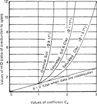
FIGURE 5.41 Diagram for coefficient Cd for load calculations for tunnels. ф is soil friction angle. (From Standard Specifications for Highway Bridges,

American Association of State Highway and Transportation Officials, Washington, D. C., 2004, with permission)

Specifications for Highway Bridges state that the earth pressure on a tunnel liner can be determined from the following equation:

W£ = CdlyS (5.56)

where WE = earth pressure at the crown, kip/ft2

Cdt = load coefficient for tunneling (from Fig. 5.41)

7 = unit weight of soil, kip/ft3 S = tunnel diameter or span, ft

The tunnel liners act in compression caused by ring thrust. If a structural member with significant stiffness is used, the effects of ring flexure must be included because the flexural stress may reduce the capacity of the member to carry load.

The design of tunnel liners generally consists of designing the liner for joint strength, wall buckling, and minimum stiffness for installation. The analysis of steel ribs with lagging is a fairly straightforward procedure. The steel ribs are generally placed at 4-ft (1.2-m) intervals on centers. The lagging must carry the load between these and is designed for moment and shear over the 4-ft (1.2-m) span. The load per linear foot may be taken as that for tunnel liner plate. The ribs must be designed to withstand the load transferred from the lagging. The stress in the steel ribs should include the effects of both flexure and thrust. The use of precast concrete tunnel liners as an initial support is
rare. The analysis is complex, but may be aided by the use of moment-thrust interaction diagrams. (See Standard Specifications for Highway Bridges, AASHTO; R. V. Proctor and T. L. White, Earth Tunneling with Steel Supports, Commercial Shearing, Inc., 1977; and T. D. O’Rourke, Guidelines for Tunneling Design, ASCE, 1984.)

Pipe Deflection by the Iowa Formula

Deflection of flexible pipes is not a design criterion in most specifications, because if pipes are properly installed with approved soil and compaction level, deflections will be within normal limits. However, the deflection for given loading and backfill conditions

Подпись: TABLE 5.26 Values of Bedding Constant K for Deflection Calculations for Flexible Pipe Bedding angle, ° K 0 0.110 30 0.108 45 0.105 60 0.102 90 0.096 120 0.090 180 0.083 Source: From A. P. Moser, Buried Pipe Design, McGraw-Hill, 2001, with permission.

can be approximated for a round pipe. The traditional method of predicting deflection is the Iowa formula introduced by M. G. Spangler and modified by R. K. Watkins:

Подпись: (5.55)DTKWr

AX = ______ _ c______________

Pipe Deflection by the Iowa Formula Подпись: total horizontal deflection, in (mm) deflection lag factor bedding constant vertical load on pipe, lb/in (kN/mm) mean radius of pipe, in (mm) modulus of elasticity of pipe material, lb/in2 (MPa) moment of inertia of pipe wall, in4/in (mm4/mm) modulus of soil reaction, lb/in2 (MPa)

EI + 0.061Er*

Values for the bedding constant may be found in Table 5.26. Because the bedding constant does not vary greatly and the bedding angle is generally not well known, it is often taken as 0.10. Values of the modulus of soil reaction are given in Table 5.27. As used in this table, the bedding material refers to the soil surrounding the pipe, not just the bedding layer on which the pipe rests. The deflection lag factor accounts for the tendency for deflections to increase over time, particularly if the soil is not well com­pacted or if the soil has a significant plastic content. The value of DL used ranges from 1.0 to 1.5. Generally, reverse curvature of a round flexible pipe occurs when the deflection reaches approximately 20 percent. Traditionally, a factor of safety of 4 is used, so deflections are limited to 5 percent.

Plastic Pipe

Introduction. Gravity flow thermoplastic pipes used in highway drainage applications are typically manufactured of high-density polyethylene (HDPE) or polyvinyl chloride (PVC). To a lesser extent acrylonitrile-butadiene-styrene (ABS) pipe is also used but is limited to drain, waste, and vent applications. Plastic pipes are always circular in cross­section. They may be either of a solid wall or profile wall design. These structures are generally designed for ring thrust by a semiempirical method that includes checks for wall area, buckling, and wall stress and strain. A check is also made to ensure the struc­ture has sufficient rigidity to withstand handling and installation forces. Thermoplastic pipes may also be designed using finite-element computer programs that model both the structure and the soil. One such program, CANDE (“Culvert Analysis and Design,” PC-TRANS, Kansas University Transportation Center, Lawrence), includes a solution based on the theoretical work of Burns and Richard (“Attenuation of Stresses for Buried Cylinders,” Proceedings of Symposium on Soil-Structure Interaction, University of Arizona, Tucson, 1964). The Burns and Richard solution is derived from generalized shell theory. The authors derived equations using a linear elastic shell in a linear elastic medium. While a thermoplastic pipe buried in soil is not a linear elastic shell in a linear elastic medium, the derived equations have been shown to have general suitability for deep burial conditions.

The current design specifications for thermoplastic pipes are rapidly evolving. There is significant research in the areas of profile design, material quality control, and long-term pipe response. One particularly interesting area is the area of profile design. Thermoplastic pipes, with the multitude of wall profiles, can be vulnerable to local wall buckling. While a localized wall buckle will rarely lead to pipe failure, it can reduce the effective physical properties of the pipe profile. AASHTO has adopted equations for determining the postbuckling physical properties of the pipe profile.

There has been no standardization of the wall profiles. Manufacturers have significant leeway in designing the pipe wall profile. General mechanical and physical properties of the more common thermoplastic materials are given in Tables 5.22 and 5.23. Because of this lack of standardization, the values in the tables do not necessarily rep­resent any manufactured pipe products, but rather are the critical design values for

TABLE 5.22 Dimensional Data for Plastic Pipes

A. PE corrugated pipes (AASHTO M 294)

Nominal

Min. I. D.,

Max. O. D.,

Min. A,

Min. C,

Min. I,

size, in

in

in

in2/ft

in

in4/in

12

11.8

14.7

1.5

0.35

0.024

15

14.8

18.0

1.9

0.45

0.053

18

17.7

21.5

2.3

0.50

0.062

24

23.6

28.7

3.1

0.65

0.116

30

29.5

36.4

3.9

0.75

0.163

36

35.5

42.5

4.5

0.90

0.222

42*

41.5

48.0

4.69

1.11

0.543

48*

47.5

55.0

5.15

1.15

0.543

B. PE ribbed pipes (ASTM F 894)

Min. I,

in4/in

Nominal

Min. I. D.,

Max. O. D.,

Min. A,

Min. C,

Cell class

Cell class

size, in

in

in

in2/ft

in

334433C

335434C

18

17.8

21.0

2.96

0.344

0.052

0.038

21

20.8

24.2

4.15

0.409

0.070

0.051

24

23.8

27.2

4.66

0.429

0.081

0.059

27

26.75

30.3

5.91

0.520

0.125

0.091

30

29.75

33.5

5.91

0.520

0.125

0.091

33

32.75

37.2

6.99

0.594

0.161

0.132

36

35.75

40.3

8.08

0.640

0.202

0.165

42

41.75

47.1

7.81

0.714

0.277

0.227

48

47.75

53.1

8.82

0.786

0.338

0.277

C. PVC profile wall pipes (AASHTO M 304)

Min. I,

in4/in

Nominal

Min. I. D.,

Max. O. D.,

Min. A,

Min. C,

Cell class

Cell class

size, in

in

in

in2/ft

in

12454C

12364C

12

11.7

13.6

1.20

0.15

0.004

0.003

15

14.3

16.5

1.30

0.17

0.006

0.005

18

17.5

20.0

1.60

0.18

0.009

0.008

21

20.6

23.0

1.80

0.21

0.012

0.011

24

23.4

26.0

1.95

0.23

0.016

0.015

30

29.4

32.8

2.30

0.27

0.024

0.020

36

35.3

39.5

2.60

0.31

0.035

0.031

42

41.3

46.0

2.90

0.34

0.047

0.043

48

47.3

52.0

3.16

0.37

0.061

0.056

Conversions: 1 in = 25.4 mm, 1 in2/ft = 2.117 mm2/mm, 1 in4/in = 16,387 mm4/mm.

*These sizes are covered in AASHTO Provisional Standard Specification for Corrugated Polyethylene Pipe, AASHTO Designation MP6-95.

Source: Standard Specifications for Highway Bridges, AASHTO, with permission.

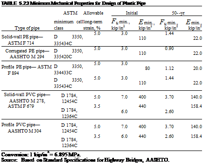
Подпись: TABLE 5.23 Minimum Mechanical Properties for Design of Plastic Pipe ASTM Allowable Initial 50- -yr Type of pipe minimum cell class long-term strain, % Fu min., kip/in2 E min., kip/in2 Fu min., kip/in2 E min., kip/in2 Solid-wall PE pipe— ASTM F 714 D 3350, 335434C 5.0 3.0 110 1.44 22.0 Corrugated PE pipe— AASHTO M 294 D 3350, 335420C 5.0 3.0 110 0.90 22.0 Profile PE pipe— ASTM F 894 D 3350, 334433C 5.0 3.0 80 1.12 20.0 D 3350, 335434C 5.0 3.0 110 1.44 22.0 Solid-wall PVC pipe— AASHTO M 278, D 1784, 12454C 5.0 7.0 400 3.70 140.0 ASTM F 679 D 1784, 12364C 3.5 6.0 440 2.60 158.4 Profile PVC pipe— AASHTO M 304 D 1784, 12454C 5.0 7.0 400 3.70 140.0 D 1784, 12364C 3.5 6.0 440 2.60 158.4 Conversion: 1 kip/in2 = 6.895 MPa. Source: Based on Standard Specifications for Highway Bridges, AASHTO.

each property. It is highly unlikely that any one product could be produced to meet all of these minimum values. Material and physical properties for a specific pipe product should be obtained from the pipe manufacturer. The tables list both long-term and initial values for tensile strength and modulus of elasticity. Use short-term values for deter­mining the response of the pipe to live loads. Use long-term values for determining the buckling capacity of the pipe. In determining the thrust response, use short-term values if the full soil prism is used for the dead load, and use long-term values if the dead load is factored through the use of the vertical arching factor.

Loads on Plastic Pipe. As discussed in Art. 5.8.2, live loads are distributed through the cover above the top of the pipe. In lieu of more exact computations, the live load pressures used for corrugated metal pipe, given in Table 5.19, can be used. The table also includes pressures for an H 25 wheel load, which is 25 percent greater than the H 20 wheel load, and an E 80 railway loading. All of the pressures in the table include an impact allowance for shallow cover.

Earth loads on flexible pipes can be highly variable. An investigation of the theoret­ical work of Burns and Richard by Dr. T. McGrath revealed that the pipe hoop stiffness is the critical factor in determining the pressure distribution about the pipe. The earth load on a thermoplastic pipe can be stated as a proportion of the soil prism load, similar to concrete and corrugated metal pipes. Based on the previously mentioned work of McGrath, the vertical arching factor (VAF) for thermoplastic pipes is

Подпись: (5.47)Подпись: VAFSh – 1.17 SH + 2.92

Подпись: (5.48)

Подпись: with

, = AMR ‘H = EA

where SH = hoop stiffness factor

MS = constrained soil modulus, lb/in2 (see Table 5.24)

R = radius to centroid of pipe, in E = long-term, 50-year modulus of elasticity, lb/in2 A = cross-sectional area of corrugation, in2/ft

In determining the dead load on the pipe, the designer may use either the soil prism load or the load factored through the use of the vertical arching factor. If the factored load is used, AASHTO requires a check of the local stability of the profile wall section. The details of the local stability check can be found in the AASHTO publication

TABLE 5.24 Design Values for Constrained Soil Modulus, Ms

Soil type and compaction condition

Stress level,

Sn-100,

Sn-95,

Sn-90,

Sn-85,

lb/ft2

lb/in2

lb/in2

lb/in2

lb/in2

150

2350

2000

1275

470

750

3450

2600

1500

520

1500

4200

3000

1625

570

3000

5500

3450

1800

650

6000

7500

4251

2100

825

9000

9300

5000

2500

1000

Si-95,

Si-90,

Si-85,

lb/in2

lb/in2

lb/in2

150

1415

670

360

750

1670

740

390

1500

1770

750

400

3000

1880

790

430

6000

2090

900

510

Cl-95,

Cl-90,

Cl-85,

lb/in2

lb/in2

lb/in2

150

533

255

130

750

625

320

175

1500

690

355

200

3000

740

395

230

6000

815

460

285

9000

895

525

345

Conversions: 1 lb/ft2 = 0.0479 kPa, 1 lb/in2 = 6.895 X 10~3 MPa.

Notes: (1) The soil types are defined by a two-letter designation that indicate general soil classification, Sn for sands and gravels, Si for silts, and Cl for clays. Specific soil groups that fall into these categories should be based on ASTM D 2487 and AASHTO M 145. (2) The numerical suffix to the soil type indicates the compaction level of the soil as a percentage of maximum dry density determined in accordance with AASHTO T-99.

Source: From Design Method for Flexible Pipe, AASHTO, 1998,

with permission.

LRFD Bridge Design Specifications. If the full soil prism is used, the profile stability check can be conservatively ignored.

The total load (pressure) is then calculated as follows: The design is calculated by multiplying the dead load by a p factor of 1.5 and the live load by a factor of 1.67. The summation of the dead load and live load is then multiplied by a у factor of 1.3.

Structural Design of Plastic Pipe. Calculations proceed as follows. The thrust in the pipe wall is

Подпись: LPlastic Pipe(5.49)

where TL = factored thrust, lb/ft

PL = factored load pressure, lb/ft2 S = pipe diameter or span, in

Подпись: A Подпись: EL Ф E Подпись: (5.50)

The required wall area to resist the thrust is

where A = required wall area, in2/ft

fu = minimum tensile strength, lb/in2 ф = capacity modification factor, 1.0

Подпись: Pcr = 1.999 Подпись: MsEI T (1 - v2) Подпись: (5.51)

Next, check for possible wall buckling. The critical buckling pressure must be greater than the factored design load pressure. The critical buckling pressure (lb/in2 or kPa) is given by the following equation:

where Ms = constrained soil modulus, lb/in2 (see Table 5.24)

R = radius to centroid of pipe, in E = modulus of elasticity, lb/in2 I = moment of inertia of pipe profile, in4/in v = Poisson ratio, 0.4

Подпись: Є і Подпись: 2DEE фЕ2 Подпись: (5.52)

Thermoplastic materials must also be checked to ensure that total wall strains do not exceed the resistance capabilities of the plastic. The pipe wall must resist the combined action of bending and thrust. Compressive strain is the critical strain since wall thrust acts purely in compression and will tend to decrease the tensile strain in the wall. Maximum permissible strain values are given in Table 5.23. The bending strain in the wall can be calculated as

where Df = pipe shape factor (see Table 5.25)

R = radius to centroid of pipe, in

ymax = distance from centroid of pipe wall to furthest pipe surface, in Д = vertical deflection, in ф = capacity modification factor, 0.5

TABLE 5.25 Shape Factors for Design of Plastic Pipe

Pipe

stiffness (PS), lb/in2 (kPa)

Gravel: GW, GP, GW-GC, GW-GM, GP-GC, and GP-GM

Sand:

SW, SP, SM, SC, GM, GC, or mixtures

Dumped to slight (<85% SPD)

Moderate to high (>85% SPD)

Dumped to slight (<85% SPD)

Moderate to high (>85% SPD)

17 (117)

4.6

5.7

5.1

6.7

20 (138)

4.4

5.4

4.9

6.4

22 (152)

4.3

5.3

4.8

6.3

28(193)

4.1

4.9

4.4

5.9

34 (234)

3.9

4.6

4.1

5.6

35 (241)

3.8

4.6

4.1

5.6

38 (262)

3.8

4.5

4.0

5.4

40 (276)

3.7

4.4

3.9

5.4

42 (290)

3.7

4.4

3.9

5.3

50 (345)

3.6

4.2

3.8

5.1

Notes: (1) Interpolate for intermediate pipe stiffness values. (2) For Class IA and IB backfill materials, use the appropriate “Gravel” column. (3) For Class IVA backfill material, use the highest shape factor for that pipe stiffness. (4) Information has been modified from ANSI/AWWA C950-88, p. 28, for pipe stiffnesses appropriate for corrugated polyethylene pipe. (5) SPD = specified minimum density.

Source: From Structural Design Method for Corrugated Polyethylene Pipe,

Corrugated Polyethylene Pipe Association, 2000, with permission.

Подпись: £h Подпись: PLR 12AE Подпись: (5.53)

and the compressive hoop, or circumferential, strain is

where all variables are as described above.

The total compressive wall strain, є, is determined by adding the bending strain and hoop strain:

є = Єь + Єh (5.54)

The equation for determining the bending strain includes the pipe vertical deflection as a design input parameter. Traditionally, the modified Iowa equation has been used to estimate expected pipe deflections. However, differences between calculated and field measured values as great as 100 percent have been reported. This is not a criticism of the equation. It certainly has applicability for small deflection pipe products such as concrete or corrugated metal. Further, with all of the technological advancements in computer modeling, to date no better equation or method has been developed.

In lieu of calculating the expected pipe deflection via the modified Iowa equation, the designer may set a maximum permissible in-field deflection limit in the project specifications. This deflection value can then be used in the design calculations with­out worry about the accuracy of the computed value.

Example: Thermoplastic Pipe Design. A 42-in-diameter (1050 mm) culvert is required for a site with 6 ft (1.83 m) of cover and an HS 20 live load. The pipe will be installed with a well-graded gravel backfill compacted to 95 percent of Proctor density. The maximum in-field deflection will be 5 percent. The pipe is an HDPE pipe with the following material properties:

Dt = inside pipe diameter, 41.85 in (1063 mm)

A = pipe wall area, 6.420 in2/ft (13.6 mm2/mm)

I = moment of inertia, 0.621 in4/in (10,176 mm4/mm)

c = distance to the centroid of the pipe wall, 1.38 in (35.0 mm)

E = modulus of elasticity, 110,000 lb/in2 (758 MPa)

fu = minimum tensile strength, 900 lb/in2 (6.21 MPa)

Подпись: PL T(PEPE Подпись: + PEPLL + I)

First, calculate the design load pressure as follows:

1.3 (1.5 X 771.6 + 1.67 X 200)

1938.8 lb/ft2 (92.8 kPa)

Plastic Pipe

Then, from Eq. (5.49), the factored thrust in the pipe wall is

3392.9 lb/ft (49.5 kN/m)

From Eq. (5.50), the required wall area to resist the thrust is

A

3392.9

1.0(3000) 1.13 in2/ft (2.39 mm2/mm)

Plastic Pipe

1938.8(41.85 + 1.38)
12(6.42)(110,000)

= 0.990 percent

The total compressive wall strain is 0.285 percent + 0.990 percent = 1.275 percent. This is less than the permissible 5 percent for HDPE, and therefore the design is acceptable.

Corrugated Metal Pipe

Introduction. Corrugated metal structures are typically manufactured of either steel or aluminum. These structures are generally designed for ring thrust by a semiempirical method that includes checks for wall area, buckling, and seam strength. A check is also

Corrugated Metal Pipe

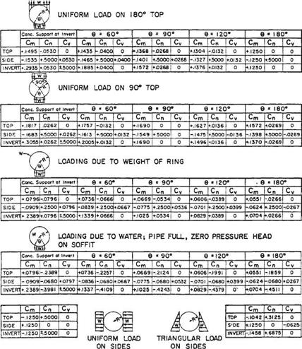
FIGURE 5.39 Coefficients for calculating moment (M), thrust (N), and shear (V) in concrete pipe under linear pressure distributions. The coefficients used are as follows: M = CmWR, N = CnW, V = CW, where W is total load in each case and R is mean radius. Sign convention: +M is tension on inside face, +N is compression, +V is positive shear for left side. (From J. M. Paris, "Stress Coefficients for Large Horizontal Pipes," Engineering News Record, vol. 87, no. 19, November 10, 1921, with permission)

made to ensure the structure has sufficient rigidity to withstand handling and installation forces. Computer programs for the design of corrugated steel pipe are available from the National Corrugated Steel Pipe Association, located in Dallas, Texas. Corrugated metal structures may also be designed using finite-element computer programs that model both the structure and the soil. The design procedure for metal box culverts and long-span structures differ somewhat from those of other corrugated metal structures.

Various methods are available for the design of corrugated metal pipe, arches, and pipe arches. Service load design is implemented by the use of safety factors that are applied to the yield stress, buckling stress, or seam strength to determine an allowable stress. Load factor design is utilized by applying load factors (P and 7) to the dead and

TABLE 5.18 Moment of Inertia and Cross-Sectional Area of Corrugated Steel Pipe

Specified thickness, in*

Corrugation pitch X depth.

0.052

0.064

0.079

0.109

0.138

0.168

0.188

0.218

0.249

0.280

in

0.111

0.140

0.170

Moment of inertia I, in4 per ft of width

VA X /4

0.0041

0.0053

0.0068

0.0103

0.0145

0.0196

2 X A

0.0184

0.0233

0.0295

0.0425

0.0586

0.0719

2 A X И

0.0180

0.0227

0.0287

0.0411

0.0544

0.0687

3 X 1

0.0827

0.1039

0.1306

0.1855

0.2421

0.3010

5 X 1

0.1062

0.1331

0.1878

0.2438

0.3011

6X2

0.725

0.938

1.154

1.296

1.523

1.754

1.990

J/> X /4 X T/A

0.0431

0.0569

0.0858

0.1157

XIX 1Щ

0.0550

0.0730

0.1111

Cross-sectional wall area A, in2 per

ft of width

VA X /4

0.608

0.761

0.950

1.331

1.712

2.093

2 X A

0.652

0.815

1.019

1.428

1.838

2.249

2 A X A

0.619

0.775

0.968

1.356

1.744

2.133

3 X 1

0.711

0.890

1.113

1.560

2.008

2.458

5 X 1

0.794

0.992

1.390

1.788

2.196

6X2

1.556

2.003

2.449

2.739

3.199

3.658

4.119

J/> X /4 X 7%t

0.511

0.715

1.192

1.729

XIX 1Щ

0.374

0.524

0.883

Conversions: 1 in = 25.4 mm, 1 in4/ft = 1366 mm4/mm, 1 in2/ft = 2.117 mm2/mm.

*Where two thicknesses are shown, top is corrugated steel pipe and bottom is structural plate, fRibbed pipe. Properties are effective values.


Подпись: 440

Source: From Handbook of Steel Drainage and Highway Construction Products, American Iron and Steel Institute, 1994, with permission.

live loads and allowing the design stresses to approach the yield stress of the material adjusted by a capacity reduction factor (ф). Load and Resistance Factor Design (LRFD) is similar but differs in details.

The calculations include checks for wall area, buckling, and installation strength. In addition, the seam strength must be checked for annular corrugated and structural – plate pipe, arches, and pipe arches.

Values for moments of inertia and wall area of steel products are given in Table 5.18, and minimum longitudinal seam strengths for steel structural plate are given in Table 5.19. Data for aluminum products can be found in the AASHTO specifications.

Loads on Corrugated Metal Pipe. As discussed in Art. 5.8.2, live loads are distributed through the cover above the top of the pipe. In lieu of more exact computations, the live load pressures given in Table 5.20 are often used. The table also includes pres­sures for an H 25 wheel load, which is 25 percent greater than the H 20 wheel load, and an E 80 railway loading. All of the pressures in the table include an impact allowance for shallow cover.

TABLE 5.19 Minimum Longitudinal Seam Strength for 6- X 2-in Steel Structural Plate

Minimum seam strength,
kip/ft (kN/m) for indicated bolt pattern

2 bolts per 3 bolts per 4 bolts per

Specified thickness, in (mm) corrugation corrugation corrugation

0.111 (2.82)

43 (627)

0.140 (3.56)

62 (905)

0.170 (4.32)

81 (1182)

0.188 (4.79)

93 (1357)

0.218 (5.54)

112 (1634)

0.249 (6.32)

132 (1926)

0.280 (7.11)

144(2101) 180 (2026) 194 (2830)

Source: Based on Standard Specifications for Highway Bridges, AASHTO.

TABLE 5.20 Highway and Railway Live Loads

Highway loading*

Railway E 80 loading*

Depth of cover, ft (m)

Load, lb/ft2 (kPa)

Depth of cover, ft (m)

Load, lb/ft2 (kPa)

H 20

H 25

1 (0.30)

1800 (86.2)

2280 (109.2)

2 (0.61)

3800 (181.9)

2 (0.61)

800 (38.3)

1150 (55.1)

5 (1.52)

2400 (114.9)

3 (0.91)

600 (28.7)

720 (34.5)

8 (2.44)

1600 (76.6)

4 (1.22)

400 (19.2)

470 (22.5)

10 (3.05)

1100 (52.7)

5 (1.52)

250 (12.0)

330 (15.8)

12 (3.66)

800 (38.3)

6 (1.83)

200 (9.6)

240 (11.5)

15 (4.57)

600 (28.7)

7 (2.13)

175 (8.4)

180 (8.6)

20 (6.10)

300 (14.4)

8 (2.44)

100 (4.8)

140 (6.7)

30 (9.14)

100 (4.8)

9 (2.74)

110 (5.3)

*See ASTM A796. Neglect live load when less than 100 lb/ft2 (4.8 kPa); use dead load only.

Source: From Handbook of Steel Drainage and Highway Construction Products,

American Iron and Steel Institute, 1994, with permission.

The earth load is considered to be the full soil prism load. This is because the vertical arching factor for corrugated metal pipe is nearly unity.

AASHTO calculations for load (pressure) are as follows. The design load pressure, P, for service load design is the sum of the applicable live load plus impact and earth load. For load factor design, the design load is calculated by multiplying the dead load by a P factor of 1.5 and the live load by a factor of 1.67. The summation of the dead load and live load is then multiplied by a 7 factor of 1.3.

Structural Design of Pipe by Service Load Design. Calculations for factory-corrugated or structural-plate structures proceed as follows: The thrust in the pipe wall is

T = P ^|) (5.37)

where T = wall thrust, lb/ft (kN/m)

P = design load pressure, lb/ft2 (kPa)

S = pipe diameter or span, ft (m)

The required wall area to resist the thrust is

A = | (5.38)

a

where A = required wall area, in2/ft (mm2/mm)

fa = allowable stress, lb/in2 (MPa) = f/SF = minimum yield stress (lb/in2) (MPa) divided by safety factor (2.0)

For steel, fy = 33,000 lb/in2 (230 MPa); for aluminum, fy = 24,000 lb/in2 (170 MPa).

After selecting a corrugation profile and sheet thickness, check for possible wall buckling. If the buckling stressfcr is less than the minimum yield stress, recalculate the required wall area using fcr for the yield stress in lieu offy. The buckling stress is given by the following equations:

Подпись: If Corrugated Metal Pipe Corrugated Metal Pipe Подпись: ,k (іV 48Em { r ) . km kS k Corrugated Metal Pipe

If

where fcr = critical buckling stress, lb/in2 (MPa) fu = 45,000 lb/in2 (steel pipe) (310 MPa)

= 31,000 lb/in2 (aluminum pipe) (210 MPa)

= 35,000 lb/in2 (240 MPa) (aluminum structural plate 0.100-0.175 in or 2.54-4.44 mm thick)

= 34,000 lb/in2 (235 MPa) (aluminum structural plate 0.176-0.250 in or 4.47-63.5 mm thick) k = soil stiffness factor = 0.22 S = pipe diameter or span, in (mm) r = radius of gyration of corrugation = V//A, in (mm)

Em = modulus of elasticity of metal, lb/in2 (MPa)

= 29,000,000 lb/in2 (20 00 X 103 MPa) (steel) or 10,000,000 lb/in2 (69 X 103 MPa) (aluminum)

I = moment of inertia of corrugation, in4/in (mm4/mm)

A = cross-sectional area of corrugation, in2/in (mm2/mm)

Pipe with annular corrugations is fabricated with longitudinal seams, and a seam strength check is required. Helically corrugated pipe has no longitudinal seams, and therefore such a check is not required. For pipe fabricated with longitudinal seams, the required seam strength is

SS = T (SF) (5.41)

where SS = required seam strength, lb/ft (kN/m)

T = wall thrust, lb/ft (kN/m)

SF = safety factor = 3.0

Check handling and installation rigidity by calculating the flexibility factor FF, in/lb:

S 2

FF = f – (5.42)

EmI

where terms are as defined above. Limit FF to the values listed in Table 5.21.

Example: Corrugated Steel Pipe Design via Service Load Design. A 48-in-diameter (1200-mm) culvert is required for a site with 6 ft (1.83 m) of cover and an HS 20 live load. Determine a suitable corrugation and sheet thickness. Use factory-corrugated pipe with a helical lock seam.

TABLE 5.21 Maximum Flexibility Factors for Metal Culverts

Material

Corrugation

Flexibility factor, in/lb

Steel

У4 and /4 in deep

4.3 X 10⁻²

Steel

1 in deep

3.3 X 10⁻²

Aluminum

У4 and /4 in deep

3.1 X 10⁻² (0.060 in thick)

6.1 X 10⁻² (0.075 in thick)

9.2 X 10⁻² (>0.060 in thick)

Aluminum

1 in deep

3.3 X 10⁻²

Steel and aluminum

Spiral rib pipe

Varies with I and with type of installation. See AASHTO Standard Specifications for Highway Bridges.

Steel

6 X 2 in

2.0 X 10~2 (pipe)

3.0 X 10~2 (pipe-arch)

3.0 X 10⁻² (arch)

Aluminum

9 X 212 in

2.5 X 10~2 (pipe)

3.6 X 10~2 (pipe-arch)

3.6 X 10⁻² (arch)

Conversions: 1 in = 25.4 mm, 1 in/lb = 5.70 mm/N.

Source: Based on Standard Specifications for Highway Bridges, AASHTO.

Подпись: H +

Corrugated Metal Pipe Corrugated Metal Pipe

First calculate the design load as follows: From Table 5.20, the live load pressure for the 6 ft (1.83 m) of cover is 200 lb/ft2 (9.6 kPa). The earth load pressure is the pressure from the soil prism load, Eq. (5.26):

The design load pressure is the sum of these loads:

Corrugated Metal Pipe

P = 771.6 + 200 = 971.6 lb/ft2 (46.5 kPa) Then, from Eq. (5.37), the thrust in the pipe wall is

= 1943 lb/ft (28.4 kN/m)

From Eq. (5.38), the required wall area to resist the thrust is

Подпись: Aff

fa

1943

= 33,000/2

= 0.118 in2/ft (0.250 mm2/mm)

From Table 5.18 make a tentative selection of corrugation profile and sheet thickness as follows: 223-in (68-mm) X f2-in (13-mm) corrugation profile, 0.064-in (1.63 mm) thickness. Properties are

A = 0.775 in2/ft = rff = 0.0646 in2/in (0.137 mm2/mm) > 0.118 in2/ft required (0.250 mm2/mm)

I = 0.0227 in4/ft = ffin>/ft = 0.00189 in4/in (31.0 mm4/mm)

r = VrA = V0.00189/0.0646 = 0.171 in (4.34 mm)

Подпись: r_ 24Em к V Xu Подпись: 0.171 / 24(29 X 10f 0.22 V 4500 Подпись: 96.7 in (2456 mm)

Next, check the buckling stress. To determine whether Eq. (5.39) or (5.40) applies, compare the span (48 in or 1200 mm) with

Подпись: fcr = fu Подпись: fX (иу 48Emі r ) Подпись: 45,000 Подпись: 45,0002 / 0.22(48) )2 48(29 X 106)  0.171 )

Because S < 96.7 in, Eq. (5.39) applies. The buckling stress is

= 39,500 lb/in2 (272 MPa)

Corrugated Metal Pipe Подпись: 482 (29 X 106)0.00189 Подпись: 4.2 X 10~2in/lb (0.239 mm/N)

Compare this with the yield stress, f = 33,000 lb/in2. Because fcr > fy, buckling does not control. Also, because there are no longitudinal seams, the seam strength check does not apply. Finally, check handling and installation rigidity by calculating the flexibility factor. From Eq. (5.42):

Table 5.21 gives the maximum value of FF for this profile as 4.3 X 10~2 in/lb (0.245 mm/N). Therefore, the design is satisfactory. Select the 233-in (68-mm) X 32-in (13-mm) corrugation profile with a 0.064-in (1.63 mm) sheet thickness.

Structural Design of Pipe by Load Factor Design. Calculations proceed as follows. The thrust in the pipe wall is

Подпись: LCorrugated Metal Pipe(5.43)

where TL = factored thrust, lb/ft (kN/m)

PL = factored load pressure, lb/ft2 (kPa) S = pipe diameter or span, ft(m)

Подпись: A Подпись: r Ф fy Подпись: (5.44)

The required wall area to resist the thrust is

where A = required wall area, in2/ft (mm2/mm) fy = minimum yield stress, lb/in2 (MPa) ф = capacity modification factor

= 1.00 for helical pipe with lock seams or fully welded seams = 0.67 for annular pipe with spot-welded, riveted, or bolted seams (including structural-plate pipe)

After selecting a corrugation profile and sheet thickness, check for possible buckling. If the buckling stress fcr is less than the yield stress, recalculate the area using fcr in lieu offy. The buckling stress is given by Eqs. (5.39) and (5.40). For pipe with longitu­dinal seams, the required seam strength SS, lb/ft, is

SS = У (5.45)

where ф is as given for Eq. (5.44). Check the flexibility factor by Eq. (5.42) and Table 5.21.

Example: Corrugated Steel Pipe Design via Load Factor Design. For the 48-in­diameter (1200-mm) culvert in the preceding example, determine a suitable corruga­tion and sheet thickness for the culvert.

First, calculate the factored load as follows:

Pl T(PePel + PePll +1)

= 1.3 (1.5 X 771.6 + 1.67 X 200) = 1938.8 lb/ft2 (92.8 kPa)

Corrugated Metal Pipe

Then, from Eq. (5.43), the factored thrust in the pipe wall is

= 1938^ у j

= 3877.6 lb/ft (56.6 kN/m)

From Eq. (5.44), the required wall area to resist the thrust is

Подпись: A1l_

Ф fy

3877.6

= 1.0 (33,000)

= 0.118 in2/ft (0.250 mm2/mm)

The remaining checks are similar to those for service load design. It can be seen that a satisfactory design is provided with the 233-in (68-mm) X (f-in (13-mm) corrugation profile with a 0.064-in (1.63-mm) sheet thickness.

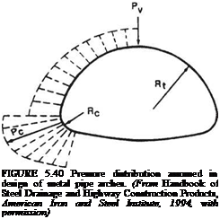
Pipe-Arch Design. The pipe-arch type of steel or aluminum culvert exerts high pressures at the corner radii, as illustrated in Fig. 5.40. For this reason, in addition to the need for designing a pipe to withstand the imposed loads, the soil at the corner radii must
be able to withstand the high bearing pressures applied to it. The anticipated corner pressure for an HS 20 live load can be calculated as follows:

Подпись: (5.46)

Подпись: FIGURE 5.40 Pressure distribution assumed in design of metal pipe arches. (From Handbook of Steel Drainage and Highway Construction Products, American Iron and Steel Institute, 1994, with permission)

(^1^LL + PEl) rl

where C1 = y1 when L2 < 72 in L2

C1 = 2 У when L2 > 72 in

L3

Pc = corner pressure, lb/ft2 (kPa)

rl = radius of the pipe-arch crown, in (mm)

rc = corner radius of the pipe arch, in (mm)

L1 = 40 + (h – 12) 1.75 L2 = L1 + 1.37s

L3 = L2 + 72

h = height of cover, in (mm) s = pipe span, in (mm)

In the application of the corner pressure equation, live load impact is not considered. Therefore, the live load pressures given in Table 5.20 should be modified to remove the impact effects. Also, in lieu of the described calculations, C1 can conservatively be assumed to be 1.

Structural Design of Long-Span and Box Culverts. Structural-plate structures that can­not, because of their long span, meet the design requirements for structural-plate pipe structures are defined as long-span structural-plate structures. These structures, which often serve as short-span bridges, are not required to meet buckling or flexibility require­ments but must have certain special features (see Art. 5.6.2). The required wall area of the corrugated metal plate is determined by the same method as for other corrugated metal pipe—Eq. (5.38) or Eq. (5.44)—but the span in the equations is replaced by twice the
radius of the top arc. In addition, certain minimum thicknesses that have been found satisfactory through experience are specified by AASHTO for the top-arc plate. Also, the structure must exhibit special features accepted by AASHTO. The design require­ments for long-span structures have been based not on an analytical analysis of the soil-structure interaction system, but upon experience with successful installations. There is ongoing research to provide for an analytical and reasonably simple method for the design of these structures.

Corrugated metal box culverts are fabricated from corrugated metal structural plate. The effects of moments on structural-plate box culverts controls over those of thrust. Because of this, box culverts typically require external stiffeners comprised of steel or aluminum structural sections bolted to the exterior of the box culvert. Rib stiffeners are spaced at not less than 2 ft (0.6 m) along the crown and not less than 4.5 ft (1.4 m) along the haunch. Design moments may be calculated from simple tables provided in AASHTO and compared against allowable moments supplied by the manufacturer of the product. Similar to any rigid frame, the moment distribution between the haunch and crown is a function of their relative stiffness. Stiffening one member attracts addition­al moment, thus shedding moment from the other. In the design of corrugated metal box culverts, the proportioning of the moment is critical to the success of the design. AASHTO provides a proportioning factor along with limiting values to ensure proper moment distribution. Unlike long-span structures, for which the design methodology is based more on experience than analysis, design procedures for metal box culverts have been developed from finite element analysis. The moment capacity includes the consid­eration of the plastic moment resistance of the structural plate and rib stiffeners.

Rigid Pipe

Introduction. There are two general types of rigid underground structures—those with a curvilinear shape, and those made up of straight walls and flat slabs. A reinforced concrete pipe is an example of the former, while a reinforced concrete box is an example of the latter. Rigid structures built in a curvilinear shape tend to act in compression. However, because of their limited deflection capability, they develop moment as well as compressive stresses. The effect of moment is reduced, however, because the curvilinear shape increases the compression in the member. Structures built with straight structural elements act very differently. The effect of moment on the individual members is so great that it is not unusual for the engineer to completely ignore any small benefit obtained from the compression of the member.

Circular rigid pipe may be designed by either the empirical D-load method, termed indirect design, or by an analytical method of direct design. If the pipe is designed by

Rigid Pipe

Rigid Pipethe indirect method, moments, thrust, and shears need not be determined. All that is necessary for the design is the total load on the pipe, the bedding factor as determined from the proposed bedding conditions, and the proposed inside and outside pipe diam­eters. If the pipe is designed by the direct method, the moments, thrust, and shears may be determined from charts prepared by the American Concrete Pipe Association (ACPA) and published in 1994 in its Concrete Pipe Technology Handbook. Otherwise they may be determined from more exact finite element methods using available computer programs. After the moments, thrust, and shears are determined, the required pipe wall thickness, concrete strength, and area of reinforcing steel may be determined.

American Society of Civil Engineers provides a specification titled Standard Practice for Direct Design of Buried Concrete Pipe Using Standard Installations (SIDD). This document presents a direct design method for reinforced concrete pipe based on extensive research using the finite element computer program Soil-Pipe Interaction Design and Analysis (SPIDA). The results of the studies are twofold. First, four standard installation types were developed, and second, a generalized pressure distribution was developed. These changes represent a major departure from the tradi­tional Marston/Spangler installations and design method.

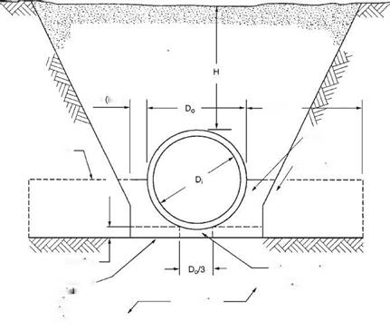
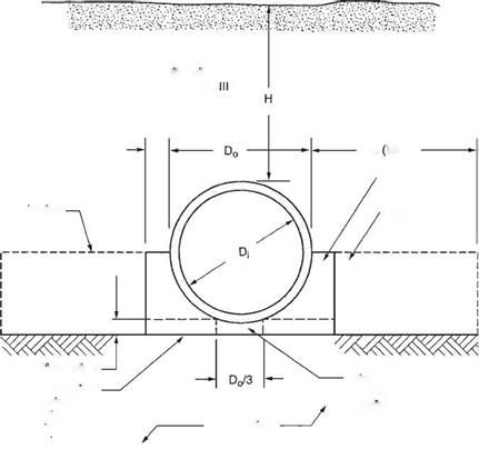
The four installation types can be applied to both a trench and an embankment instal­lation. Unlike Marston/Spangler design theory, the SIDD method does not differentiate between these two installation types. The nomenclature used in SIDD is given in Figs. 5.34 and 5.35, standard installations for trenches and embankments, respectively.

Overfill Soil

Category I, II, III

Dn/6 Min.)

Подпись: D0 (Min.)

Haunch

Springline

Lower Side

Подпись: Bedding

Rigid Pipe Rigid Pipe

Middle bedding loosely

Подпись: Foundationcompaction each

side, same

requirements

as haunch

Подпись: Lower Side

Rigid Pipe Rigid Pipe Rigid Pipe
Подпись: D</6 (Min.) Подпись: D0 Min.)

Springline

requirements

as haunch

FIGURE 5.35 Standard embankment installation. (From Concrete Pipe Design Manual, American Concrete Pipe Association, 2007, with permission)

Note that the bedding detail requires the bedding under the middle one-third of the pipe diameter to be left uncompacted. This is so that the pipe can properly seat itself in the bedding, resulting in a greater length of support along the bottom circumference of the pipe.

SIDD is only intended for use on circular pipe. The ACPA recommends that arch and elliptical pipe be designed using traditional Marston/Spangler design methods.

Live Loads. As discussed in Art. 5.8.2, live loads are distributed through the cover above the top of the pipe. The ACPA computed live load distribution factors for critical loading cases using standard AASHTO methodologies as given in the Concrete Pipe Design Manual, American Concrete Pipe Association, 2007. The results are summa­rized as follows: The pressure at the crown of the pipe is
Rigid PipeAll

where ctl = pressure intensity, lb/ft2 (kPa)

P = wheel load, lb (kN)

If = impact factor

All = distributed live load area, ft2 (m2) The total live load is

Подпись: (5.29)W = WdLSL

where WL = total live load, lb (kN)

Wd = live load on pipe, lb/ft2 (kN/m2)

SL = outside pipe diameter or width of All transverse to longitudinal axis of pipe, whichever is less, ft (m)

L = length of All parallel to longitudinal axis of pipe, ft (m)

and

(5.30)

where

Le = L + 1.75 (^)

(5.31)

Please see the referenced ACPA manual for full details and for charts summarizing maximum live loads on reinforced concrete pipes.

For rigid structures where the cover is less than 2 ft (600 mm), the wheel load is applied as a concentrated load and there is no assumed distribution due to the fill. Since most concrete pipes have 2 ft (600 mm) or more of cover, this generally applies only to reinforced concrete box culverts or three-sided culverts. The distribution length longitudinally along the top slab of the structure for the wheel loads applied as concentrated loads is defined as the distance E, ft (mm), given by

E = 4 + 0.06S in U. S. Customary units (5.32a)

E = 1220 + 0.06S in SI units (5.32b)

where S is the span in ft (mm). The live load may be distributed to the bottom slab of a reinforced concrete box culvert over a longitudinal distance equal to the width of the top slab strip increased by twice the box height.

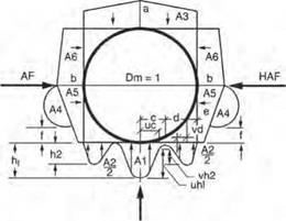
Load Distribution for Rigid Pipe. The pipe-soil system will distribute the applied earth load about the circumference of the pipe. The distribution is far from uniform. The SIDD specification includes an earth pressure distribution, sometimes called the Heger pressure distribution, for the distribution of loads about a concrete pipe. Figure 5.36 shows the pressure distribution as a function of several nondimensional arching factors and pressure distribution ratios. The figure also provides tabular data for the arching factors and pressure distribution ratios for each of the four standard installations. These factors are then multiplied by the soil prism load to obtain the magnitude of the pressures about the pipe. A full discussion on the development of the earth pressure distribution can be found in Concrete Pipe Technology Handbook, American Concrete Pipe Association, 1994.

The use of the SIDD earth pressure distribution requires that the soil types and compaction levels meet exact specifications. The soil material and compactions requirements and bedding thickness requirements for the four SIDD installations are given in Table 5.12. SIDD soil type designations are given in Table 5.13.
VAF


Rigid Pipe

Подпись: Installation Type VAF HAF A1 A2 A3 A4 A5 A6 a b C e f U V і 1.35 0.45 0.62 0.73 1.35 0.19 0.08 0.18 1.40 0.40 0.18 0.08 0.05 0.80 0.80 2 1.40 0.40 0.85 0.55 1.40 0.15 008 0.17 1.45 0.40 0.19 0.10 0.05 0.82 070 3 1.40 0.37 1.05 0.35 1.40 0.10 0.10 017 1.45 0.36 0.20 0.12 005 0.85 0.60 4 1.45 030 1.45 0.00 1 45 0.00 011 0.19 1.45 0.30 0.25 0.00 * 0.90
Notes:

1 VAF and HAF are vertical and horizontal arching factors These coefficients represent non­

dimensional total vertical and horizontal loads on the pipe, respectively. The actual total vertical and horizontal loads are (VAF) X (PL) and (HAF) X (PL), respectively, where PL is the prism load.

2. PL, the prism load, is the weight of the column of earth cover over the pipe outside diameter and is calculated as:

Rigid PipeDo

12

3. Coefficients A1 through A6 represent the integration of non-dimensional vertical and horizontal components of soil pressure under the indicated portions of the component pressure diagrams (i. e. the area under the component pressure diagrams). The pressures are assumed to vary either parabolically or linearly, as shown, with the non-dimensional magnitudes at governing points represented by hi, h2. uh1. vh2, aandb. Non-dimensional horizontal and vertical dimensions of component pressure regions are defined by c, d. e, vc, vd, and t coefficients

4. d is calculated as (0.5 -c-e).

hi is calculated as (1.5A1)/(c) (t+u). h2 is calculated as (1.5A2)/((d) (1+v) + (2e)J

TABLE 5.12 Standard Soils and Minimum Compaction Requirements for Concrete Pipe

Installation

type

Bedding thickness

Haunch and outer bedding*

Lower side*

Type 1

Do/24 minimum, not less than 75 mm (3 in). If rock foundation, use Do/12 minimum, not less than 150 mm (6 in).

95% Category I.

90% Category I,

95% Category II, or 100% Category III.

Type 2

Do/24 minimum, not less than 75 mm (3 in). If rock foundation, use Do/12 minimum, not less than 150 mm (6 in).

90% Category I or 95% Category II.

85% Category I,

90% Category II, or 95% Category III.

Type 3

Do/24 minimum, not less than 75 mm (3 in). If rock foundation, use Do/12 minimum, not less than 150 mm (6 in).

85% Category I,

90% Category II, or 95% Category III.

85% Category I,

90% Category II, or 95% Category III.

Type 4

No bedding required, except if rock foundation, use Do/12 minimum, not less than 150 mm (6 in).

No compaction required, except if Category III, use 85% Category III.

No compaction required, except if Category III, use 85% Category III.

*Compaction and soil symbols like “95% Category I” refer to “Category I soil material with minimum standard Proctor compaction of 95%.”

Source: From Concrete Pipe Design Manual, American Concrete Pipe Association, 2007, with permission.

TABLE 5.13 Equivalent USCS and AASHTO Soil Classifications for SIDD Soil Designations

SIDD soil

Representative soil types

Percent compaction

USCS

Standard

AASHTO

Standard

Proctor

Modified

Proctor

Gravelly sand

SW, SP, GW, GP

A1, A3

100

95

(Category 1)

95

90

90

85

85

80

80

75

61

59

Sandy silt

GM, SM, ML; also

A2, A4

100

95

(Category II)

GC, SC with less

95

90

than 20% passing

90

85

no. 200 sieve

85

80

80

75

49

46

Silty clay

CL, MH, GC, SC

A5, A6

100

90

(Category III)

95

85

90

80

85

75

80

70

45

40

Example: Earth Load on Concrete Pipe. A 60-in-diameter (1524-mm) concrete pipe with 6-in (152-mm) walls is to be installed under 12 ft (3.66 m) of cover using a SIDD Type 2 installation. The backfill is sandy silt compacted to a density of 120 lb/ft3 (19 kN/m3). Determine the vertical load acting at the crown and invert of the pipe and the horizontal load acting at the springline.

Подпись: Wc = y
Подпись: H +
Подпись: Do (4 - ■*)
Подпись: D
Подпись: = 120
Подпись: 12 +
Подпись: 6 (4 — ^)
Подпись: 6

Calculate the soil prism load using Eq. (5.26) as

= 9104 lb/ft (133 kN/m)

From Fig. 5.36, for a Type 2 installation the crown VAF coefficient is 1.40 and the spring­line horizontal arching factor (HAF) coefficient is 0.40. Use Eq. (5.27) to determine the vertical design load:

WEV = VAF (Wc)

= 1.40 (9104)

= 12,746 lb/ft (186 kN/m)

Also use Eq. (5.27) to determine the horizontal design load:

Weh = HAF (Wc)

= 0.40 (9104)

= 3642 lb/ft (53 kN/m)

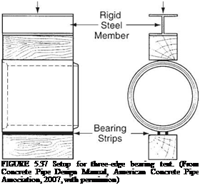
Structural Design of Concrete Pipe by Indirect Design. The indirect design method is an empirical method in which the pipe is tested by the three-edge bearing test (Fig. 5.37), and is subjected to a previously calculated load. If the pipe supports the application of the load without exceeding a crack width criterion of 0.01 in (2.5 mm), it is considered acceptable for the application for which it was manufactured. Even though AASHTO, ASCE, and ACPA promote the use of the SIDD direct design method for concrete pipe, the traditional indirect design method is still in widespread use.

The concept of the bedding factor is used in the indirect design method to relate the load-carrying capacity of an installed pipe to that of a pipe in a three-edge bearing test. In other words, the bedding factor is the ratio of the field applied load to the three-edge bearing load. For any given load, with a better installation, a lower-strength pipe is needed than would be required with an installation of poorer quality. The bed­ding factor is a function of the following:

1. The quality of the bedding material

2. The intimacy of contact between the bedding and the pipe

3. The length over which the bedding supports the pipe

4. The quality of side fill material

5. The length over which the side fill responds to pipe deflection with passive earth pressure

Подпись: FIGURE 5.37 Setup for three-edge bearing test. (From Concrete Pipe Design Manual, American Concrete Pipe Association, 2007, with permission)

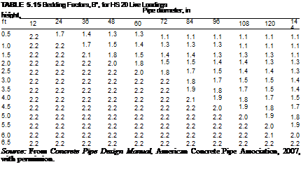
The ACPA conducted parametric studies of the four standard SIDD installations to determine appropriate bedding factors for use in the indirect design method. These values are presented in Table 5.14. More exact bedding factors for trench installations are published in Concrete Pipe Design Manual, American Concrete Pipe Association, 2007. When live loads control the design of a concrete pipe (less than 7 ft or 2.1 m of cover), a “bedding factor” for the live load must also be considered. These live load bedding factors are given in Table 5.15. Where the pipe is jacked, it maintains good contact in the area of the invert. In addition, it is common practice to grout outside the pipe after jacking operations are complete. Because of this, a bedding factor as high as 3 may be used for jacked pipe.

The load on the pipe is determined as discussed above and in Art. 5.8.2. The earth load is determined by adjusting the prism load by the arching factor. The earth load is combined with the structure dead load and any hydrostatic loads to obtain the total dead load. The dead load is then combined with the live load and impact load to obtain

Standard installation

TABLE 5.14 Bedding Factors for Dead Load under Embankment Conditions, Bro

Pipe

diameter, in

Type 1

Type 2

Type 3

Type 4

12

4.4

3.2

2.5

1.7

24

4.2

3.0

2.4

1.7

36

4.0

2.9

2.3

1.7

72

3.8

2.8

2.2

1.7

144

3.6

2.8

2.2

1.7

Notes: (1) For pipe diameters other than those listed, embankment con­dition factors can be obtained by interpolation. (2) Bedding factors are based on the soils being placed with the minimum compaction specified.

Source: From Concrete Pipe Design Manual, American Concrete

Pipe Association, 2007, with permission.

Подпись: TABLE 5.15 Bedding Factors, B^, for HS 20 Live Loadings , . , Pipe diameter, in height, ft 12 24 36 48 60 72 84 96 108 120 144 0.5 2.2 1.7 1.4 1.3 1.3 1.1 1.1 1.1 1.1 1.1 1.1 1.0 2.2 2.2 1.7 1.5 1.4 1.3 1.3 1.3 1.1 1.1 1.1 1.5 2.2 2.2 2.1 1.8 1.5 1.4 1.4 1.3 1.3 1.3 1.1 2.0 2.2 2.2 2.2 2.0 1.8 1.5 1.5 1.4 1.4 1.3 1.3 2.5 2.2 2.2 2.2 2.2 2.0 1.8 1.7 1.5 1.4 1.4 1.3 3.0 2.2 2.2 2.2 2.2 2.2 2.2 1.8 1.7 1.5 1.5 1.4 3.5 2.2 2.2 2.2 2.2 2.2 2.2 1.9 1.8 1.7 1.5 1.4 4.0 2.2 2.2 2.2 2.2 2.2 2.2 2.1 1.9 1.8 1.7 1.5 4.5 2.2 2.2 2.2 2.2 2.2 2.2 2.2 2.0 1.9 1.8 1.7 5.0 2.2 2.2 2.2 2.2 2.2 2.2 2.2 2.2 2.0 1.9 1.8 5.5 2.2 2.2 2.2 2.2 2.2 2.2 2.2 2.2 2.2 2.0 1.9 6.0 2.2 2.2 2.2 2.2 2.2 2.2 2.2 2.2 2.2 2.1 2.0 6.5 2.2 2.2 2.2 2.2 2.2 2.2 2.2 2.2 2.2 2.2 2.2 Source: From Concrete Pipe Design Manual, American Concrete Pipe Association, 2007, with permission.

the total load. The appropriate load to be applied to the pipe for the three-edge bearing test may be found by dividing the total load by the appropriate bedding factor as deter­mined from the installation conditions. This final value is termed the required minimum three-edge bearing load (TEB). If the pipe is nonreinforced, a safety factor of between 1.25 and 1.5 should be applied to the load. This is because as soon as the nonreinforced pipe cracks, it has reached its ultimate strength. However, a reinforced concrete pipe has significant postcracking strength. There is a factor of 1.25 to 1.5 between the TEB load and the ultimate load for a reinforced concrete pipe, the factor varying with the pipe diameter.

Подпись: ——D WL + — BfD BfL Подпись: TEB(5.33)

where WD = dead load, lb/ft (kN/m)

WL = live load + impact, lb/ft (kN/m)

BfD = dead load bedding factor (see Table 5.14)

BfL = live load bedding factor (see Table 5.15)

In the application of this equation, if the dead load bedding factor is greater than the live load bedding factor, then the dead load bedding factor should be used in lieu of the live load bedding factor.

Concrete pipe is typically specified by its D-load value (lb/ft/ft or kN/m/m) defined as follows:

Подпись: (5.34)required TEB D-load = —-

D

where Di = inside pipe diameter, ft (m)

Example: Concrete Pipe Design via Indirect Design. Using the same 60-in (1524-mm) concrete pipe from the previous example, determine the required D-load pipe for the 12 ft (3.66 m) of cover using a SIDD Type 2 installation. Assume a 5-in-thick (127-mm) pipe wall.

The earth load was previously determined to be 12,764 lb/ft (186 kN/m). With 12 ft (3.66 m) of cover, the live load is negligible. From Eq. (5.23a), the pipe load is

Wp = 3.3h (Dt + h)

= 3.3 (5) (60 + 5)

= 1073 lb/ft (16 kN/m)

From Table 5.14, the dead load bedding factor is 2.83; therefore, using Eq. (5.33), the three-edge bearing load is

Подпись: TEB——+ + ——+

BfD BfL

= 12,764 + 1073
2.83

= 4889 lb/ft (71 kN/m)

and from Eq. (5.34) the required D-load is

required TEB

D-load = —і—————-

Di

= 4889 5

= 978 lb/ft/ft (47 kN/m/m)

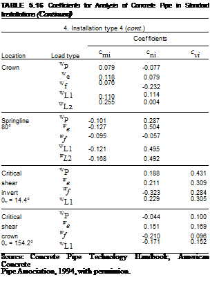
Structural Design of Concrete Pipe by Direct Design. The direct design procedure for analyzing a concrete pipe is based not on empirical methods, but on engineering analysis. Consequently, the engineer may determine precisely what strength of con­crete, wall thickness, and reinforcement are necessary. However, the method is more complex and does not lend itself to direct hand calculations. The load on the pipe is determined in the same manner as for indirect design. Then the moments, thrusts, and shears can be calculated. The distribution of the load about the pipe is given by the Heger pressure distribution.

To encourage the use of the direct design method, the ACPA has published, in the Concrete Pipe Technology Handbook, a series of charts (see Table 5.16) presenting values of nondimensional coefficients Cm, Cni, and Cvi for each of the following load cases:

• Pipe load, Wp

• Earth load, We

• Water load, Wf

• Live load, WL

TABLE 5.16 Coefficients for Analysis of Concrete Pipe in Standard Installations

1. Installation type 1

Location

Load type

Coefficients

Crn

Cni

Cv,

Invert

Wp

0.225

0.077

We

0.091

0.188

Wf

0.088

– 0.445

WL1

0.075

0.250

WL2

0.165

– 0.046

Crown

Wp

0.079

-0.077

We

0.083

0.157

Wf

0.057

-0.187

WL1

0.068

0.200

WL2

0.236

0.046

Springline

WP

-0.091

0.249

90°

We

-0.077

0.500

Wf

-0.064

– 0.068

WL1

-0.065

0.500

WL2

-0.154

0.500

Critical

Wp

0.174

0.437

shear

We

0.219

0.143

invert

Wf

– 0.408

0.141

Є„ = 12°

WL1

0.270

0.150

Critical

Wp

-0.055

0.083

shear

We

0.205

0.117

crown

Wf

-0.176

0.062

0v = 159°

WL1

0.250

0.100

2. Installation type 2

Invert

Wp

0.227

0.077

we

0.122

0.169

W!

0.111

-0.437

WL1

0.107

0.205

WL2

0.189

-0.035

Crown

Wp

0.079

-0.077

We

0.094

0.126

Ws

0.062

– 0.204

WL1

0.080

0.171

WL2

0.241

0.035

Springline

Wp

-0.091

0.249

90°

we

-0.090

0.500

wf

-0.070

– 0.068

WL1

-0.078

0.513

WL2

-0.160

0.500

TABLE 5.16 Coefficients for Analysis of Concrete Pipe in Standard Installations (Continued)

2. Installation type 2 (cont.)

Coefficients

Location

Load type

Cn,

Cv,

Critical

W

0.177

0.437

shear

We

0.218

0.198

invert

W

-0.386

0.193

0v = 12.3°

WL1

0.256

0.188

Critical

WP

-0.050

0.088

shear

We

0.185

0.136

crown

Wf

-0.181

0.074

0v = 157.3°

WL1

0.205

0.137

3. Installation type 3

Invert

WP

0.230

0.077

We

0.150

0.163

W

0.133

-0.425

WL1

0.136

0.199

WL2

0.211

-0.023

Crown

WP

0.079

-0.077

We

0.103

0.107

Wf

0.068

-0.215

W

WL1

0.091

0.149

WL2

0.247

0.023

Springline

WP

-0.097

0.271

85°

We

-0.103

0.500

Wf

-0.081

-0.063

WL1

-0.126

0.497

WL2

-0.155

0.496

Critical

WP

0.177

0.437

shear

We

0.224

0.249

invert

Wf

-0.363

0.238

0v = 12.7°

WL1

0.273

0.224

Critical

WP

-0.044

0.094

shear

We

0.173

0.150

crown

Wf

-0.193

0.085

0v = 156°

WL1

0.224

0.124

4. Installation type 4

Invert

WP

0.235

0.077

We

0.191

0.128

W

0.160

-0.403

WL1

0.185

0.152

WL2

0.237

-0.004

Подпись: TABLE 5.16 Coefficients for Analysis of Concrete Pipe in Standard Installations (Continued) 4. Installation type 4 (cont.) Coefficients Location Load type Cmi Cni Cvi Crown WP 0.079 -0.077 We 0.118 0.079 Wf 0.076 -0.232 WL1 0.110 0.114 WL2 0.255 0.004 Springline WP -0.101 0.287 80° We -0.127 0.504 Wf -0.095 -0.057 WL1 -0.121 0.495 WL2 -0.168 0.492 Critical WP 0.188 0.431 shear We 0.211 0.309 invert Wf -0.323 0.284 0v = 14.4° WL1 0.229 0.305 Critical WP -0.044 0.100 shear We 0.151 0.169 crown Wf -0.210 0.096 0v = 154.2° WL1 -0.171 0.152 Source: Concrete Pipe Technology Handbook, American Concrete Pipe Association, 1994, with permission.

These coefficients are used to directly calculate the pipe wall moments, thrusts, and shears, respectively, for each of the four standard installations. The thrusts and shears can be computed by multiplying the magnitude of the load case by the corre­sponding Cni and Cvi coefficients. The moment calculation is more complex in that the resulting moment is computed by the following equation:

Подпись: (5.35)M. = KC. ™

i mi 2

where Mi = moment due to the pertinent load case, lb • ft/ft (kN • m/m)

Cmi = moment coefficient for the pertinent load case Wi = magnitude of the pertinent load case, lb/ft (kN/m)

D = mean pipe diameter, in (mm)

K = 1.0 for U. S. Customary units (0.0121 for SI units)

For more precise calculations, the designer can utilize the FHWA-developed computer program PIPECAR. The program gives calculated moments, thrusts, and shears. It will also design the pipe utilizing either direct or indirect design procedures. After determining the forces acting on the pipe, the wall thickness, concrete strength, and amount of reinforcing can be calculated. The software follows the detailed design pro­visions in the AASHTO Standard Specifications for Highway Bridges.

Rigid Pipe

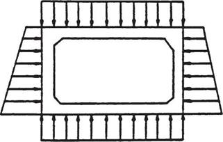
FIGURE 5.38 Pressure distribution used for design of concrete box culverts.

(From "Hydraulic Design of Highway Culverts," Hydraulic Design Series No. 5, FHWA, with permission)

For a complete discussion on the design of concrete pipe, including methods for designing elliptical and arch-shaped pipe, see Standard Practice for Direct Design of Buried Concrete Pipe Using Standard Installations (SIDD), ASCE, 1998; Concrete Pipe Technology Handbook, ACPA, 1994; Concrete Pipe Design Manual, ACPA, 2007; and Standard Specifications for Highway Bridges, AASHTO, 2003.

Structural Design of Boxes and Three-Sided Culverts. The assumed load distribution for reinforced concrete box culverts is shown in Fig. 5.38. The fluid load and structure load are the same as those used for circular concrete pipe (see Art. 5.8.2). The vertical component of the earth load is considered to be the soil prism load. The horizontal component of the earth load is specified by AASHTO such that the structure is designed using both a 30-lb/ft3 (4.8-kN/m3) and 60-lb/ft3 (9.6-kN/m3) lateral earth pressure. The live load is distributed through the soil cover as discussed in Art. 5.8.3. Three-sided structures are designed using similar load theory except the vertical reac­tion at the base of the structure is confined to the thickness of the leg.

Box culverts can be designed with either fixed or pinned corners. All box culverts with spans greater than about 8 ft (2.4 m) are designed with fixed corners. Three-sided culverts are generally designed with fixed corners exclusively. Those structures designed with pinned corners are designed for simple beam moments, and the lateral earth pressure of 60 lb/ft3 (9.6 kN/m3) is the only condition for which the sidewall need be designed. Because fixed corners transfer moments around the corners, applying the 60-lb/ft3 (9.6-kN/m3) lateral pressure will reduce the positive moments in the adjacent members when compared with the application of 30 lb/ft3 (4.8 kN/m3). For this reason, structures with fixed corners must be designed for both lateral load conditions to ensure that all maximum moments in each member are found. Table 5.17 indicates the loading condi­tions that generally control the design of the top slab and side walls of concrete box cul­verts for moment and shear. After determining maximum moments and shears, the designer may utilize standard principles of reinforced concrete design to size the mem­bers and calculate the necessary reinforcement.

As is evident from the foregoing, and is true for any structural design, many different loading conditions must be investigated to ensure the maximum stresses are determined. To reduce design time, the FHWA has developed the computer program BOXCAR,

Подпись: TABLE 5.17 Loading Conditions That Generally Control Design of Concrete Box Culverts for Moment and Shear Member Live load position Lateral pressure, lb/ft3 Lateral pressure, kN/m3 Type of moment Top slab 0.5 of span length 30 4.8 Positive Top slab and sidewall 0.3 of span length 60 9.6 Negative Sidewall No live load 60 9.6 Positive

which may be used for the structural analysis and design of reinforced concrete box culverts.

Structural Design of Cast-in-Place Pipe. Because cast-in-place concrete pipe has no reinforcement, its flexural strength is limited. In this type of structure, the effects of the compression on the member keep the effects of the moment below the modulus of rupture of the concrete, and no reinforcing is necessary. Also, because it is cast against the ground at the invert and walls, it has excellent bedding conditions, and this contributes to a reduction in moments, thrusts, and shears.

The moments, thrust, and shears can be calculated using the uniform load system developed by J. M. Paris. This system provides a method for determining maximum stresses through the application of nondimensional load coefficients, similar to the direct design of concrete pipe. As indicated in Fig. 5.39 the Cm coefficients are multi­plied by the load and the mean radius to obtain the moment, and the Cv and Cn coeffi­cients are multiplied by the load to obtain shears and thrusts.

Once these have been determined, normal stresses can be calculated from the funda­mental equation

Подпись: (5.36)_T ± MM ~A ± I

where fc = concrete stress, lb/in2 (MPa)

T = thrust, lb/in (N/mm)

A = wall area, in2/in (mm2/mm)

M = bending moment, in • lb/in (mm • N/mm) c = distance from neutral axis to extreme fiber, in (mm)

I = moment of inertia of wall, in4/in (mm4/mm)

Because the concrete is unreinforced, the stress may not exceed the modulus of rupture of the concrete adjusted by an appropriate safety factor. The FHWA recommends that the use of cast-in-place pipe on federal-aid highway projects be monitored through experimental projects in locations under roadways or with moderate to high fills.

Structural Design of Special Shapes. Most of the special shape structures are con­sidered soil-structure interaction systems and require complex structural analysis. They are typically analyzed using the finite-element method. Design is then completed using standard principles of reinforced concrete design. The manufacturers’ of these structures maintain a catalog of designs for common size and loading conditions.