Materials CHOOSING CAULKS AND SEALANTS
IF YOU WALK DOWN the caulk and sealant aisle at any well-stocked hardware store or home center, it’s easy to feel overwhelmed by the variety of products available. For quite a few years now, the terms "caulk" and "sealant" have been used interchangeably. In technical terms, sealants are supposed to be more flexible than caulks, meaning that they are able to expand and contract with the movement of materials. But even caulk and sealant manufacturers have different definitions for these materials. For this reason, it’s smart to ask local builders and knowledgeable building – material suppliers which caulks and sealants are recommended for various jobs.
Although manufacturers haven’t cleared up the distinction between caulks and sealants, they have improved their labeling with regard to specific applications. For example, "painter’s caulk" is an inexpensive latex-type caulk that is primarily used to fill gaps in and around interior trim prior to painting. Caulk that is labeled "for kitchen and bathroom use" is waterproof and will adhere to tile, porcelain sinks, acrylic shower units, and other surfaces found in those rooms. Silicone and urethane sealants are usually more expensive than acrylic or latex-acrylic caulks and are primarily used in exterior applications where extra durability, flexibility, and weather resistance are important.
Materials FIBERGLASS AND CELLULOSE INSULATION

THE TWO MOST COMMON TYPES of insulation used in homes today are fiberglass and cellulose. Both are partially manufactured from recycled materials. Fiberglass is made from 25% recycled bottles and other types of glass that are heated and spun into fibers. Cellulose insulation is made from 75% recycled newsprint which is treated with fire retardant.
Fiberglass comes in batts that are made in different widths and thicknesses. For shipping and storage, the batts are rolled up like long, thick blankets. Loose-fill fiberglass insulation is also available, but batts are much more common. Cellulose is usually blown into attic spaces and wall cavities (see the photo at right). Blowers can often be rented at supply stores, but usually an insulation contractor is hired to install cellulose. Cellulose is somewhat more expensive than fiberglass but has a higher R-value per inch, so it can end up saving you more money in energy costs.
Like roof-shingle coverage, insulation coverage is calculated by the square foot. Add up the total square footage of the floor, the ceiling, and all the
exterior walls. Unless you have an entire wall of doors and windows, don’t subtract the wall openings. You may end up with a little extra insulation, but you can always put it in the attic.
If you’re buying insulation at a home center or an equivalent store, you’ll find the per-roll coverage on the label. If you’re buying it from a professional supplier, you simply need to provide the total square footage and whether the stud (and joist) bays are 16 in. o. c. or 24 in. o. c. That’s because fiberglass batts are either 15
in. or 23 in. wide and are sized to fit between studs and joists at conventional spacings. Long, uncut rolls work well between floor and ceiling joists. Precut sections are also available for standard 8-ft.-high walls and save on installation time.
sufficient flexibility to maintain a seal even though the joint expands and contracts slightly. For advice on selecting caulks and sealants, see the sidebar on the facing page.
If you plan to use caulk or sealant to fill a gap wider than / in., its a good idea to insert a backer rod into the joint before you apply the sealant. Available where caulks and sealants are sold, backer rod is made from dense, compressible foam. When wedged into a joint, it helps seal the area and lets you apply a thinner bead of caulk or sealant.
STEP 2 Insulate the Walls, Ceilings, and Floors
Although the reason for sealing cracks and gaps in a house frame may be fairly obvious— you don’t want cold breezes (or hot air, depending on where you live) blowing through the house—the function of insulation may not be as evident. It is not to block airflow but rather to create pockets of dead air. Air pockets do the actual insulating work, while the insulation fibers or beads simply hold the air in place. That’s why jamming fiberglass insulation into a too-small space
STEP 1 Seal Penetrations in the Walls, Ceilings, and FloorsWhen you think about sealing a house, remember how much frigid air can go through a small opening in a sweater or a jacket. Even a tiny hole in a woolen mitten can make your finger numb with cold. The same thing can happen in a house. We had single – glazed, double-hung windows in that old prairie home where I grew up. In the spring, the windows were nice—we could open them wide to let in fresh breezes and the songs of meadowlarks announcing warmer weather. In the winter, though, that loose-fitting sash was a fright. My mother gave us thin strips of cloth to stuff between the window frame and the sash in hopes of slowing the icy winds that would soon roll down from the north. Today, we have the materials and the knowhow to seal a house effectively. The materials and techniques vary, depending on the type of sealing work that needs to be done. Sealing a house to limit air infiltration and energy loss begins early in the construction process and continues until the last bit of insulation work is done. As explained in chapter 3, the mudsill should be sealed to the foundation with a resilient gasket material, known as sill seal, or with two thick beads of silicone caulk. Before the exterior walls are raised, it’s also a good idea to apply two beads of silicone sealant beneath their bottom plates. If this was
Once the walls are framed, its important to install insulation in the sections that will be inaccessible after the wall sheathing is applied. As discussed in chapter 4, these areas include the voids or spaces in the framing for corners, channels, and headers. Likewise, pay attention to areas where tubs and shower units will be installed in exterior walls. You don’t want the stud cavities in these areas to be blocked off before you have a chance to insulate them.
When installing windows and doors, apply a generous bead of sealant on the flange or the back of the exterior trim. Do this just prior to installation, as explained in chapter 6. Make sure that kitchen soffits and dropped ceilings (especially those with heating or cooling ducts inside) are completely sealed off from wall and attic spaces. Use drywall or OSB, and do it now, if you haven’t already. These steps help prevent moisture-laden indoor air from moving into wall or attic areas, where it can condense and create major moisture problems. Spray-foam insulation can handle a multitude of sealing tasks Packaged in a pressurized can, foam insulation is extremely useful when it comes to filling gaps; sealing openings; and insulating narrow, confined spaces where fiberglass insulation doesn’t easily fit (see the photo at right). Although it’s not cheap, spray-foam insulation is so helpful that I don’t build a house without it. It’s available in expanding and nonexpanding versions. I prefer the expanding type, because it does a better job of spreading out to fill voids. If you apply too much and the foam starts to expand beyond the intended area, don’t worry. Come back later, after the foam has hardened, and trim off the excess with a utility knife. Don’t try to wipe off excess foam when the material is still sticky; you’ll just create a mess. Here are some of the areas in the house where spray foam can be used: IN HOLES IN BOTTOM PLATES. Use foam to fill the spaces around plumbing pipes, electrical or cable wires, and ducts that pass through the bottom plates of walls. It’s especially important to seal off these routes, which can bring cold air into your living space, when building on a crawl-space foundation. IN HOLES IN TOP PLATES. It’s very important to seal holes in the top plates of walls. This helps prevent moist indoor air from entering a cold attic, where it can condense and cause moisture problems. AROUND WINDOWS AND DOORS. I’ve often seen folks use a screwdriver or another narrow tool to stuff fiberglass insulation between trimmers and king studs (see the photo on p. 198). Although this helps to some degree, fiberglass insulation loses insulating value
AROUND PLUMBING AND ELECTRICAL LINES THAT PASS THROUGH EXTERIOR WALLS. If your house has exterior faucets, seal the hole around each one with foam insulation. Holes for outdoor electrical lines and outlet boxes in exterior walls should also be sealed. Caulks and sealants can be useful on small openings For Filling small gaps (up to Z in. or so), caulks and sealants sometimes work as well as, or better than, foam. A good sealant has Repeated Load Triaxial Testing of Unbound Granular MaterialsThe repeated load triaxial testing (RLT) (also known as the cyclic triaxial test) method is commonly used to establish the mechanical characteristics of granular materials. During the testing, a cylindrical specimen is compacted to a desired level and then tested by applying confining and vertical stresses. Two variants exist: • a constant confining pressure (CCP) method; and • a variable confining pressure (VCP) method. In the CCP-method the sample is initially subjected to a hydrostatic confining pressure ac, which induces an initial strain ec (unmeasured in the test, but it is the same in
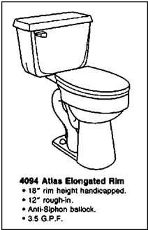
all directions for isotropic material behaviour and, thus, can be estimated). The axial stress is then cycled at a constant magnitude q, which induces the cyclic resilient axial strain As. In the VCP-method both the axial and the radial stresses are cycled. The RLT can be used to obtain both the stiffness characteristics as well as the ability of the material to withstand accumulation of permanent deformation during pulsating loading (Gomes-Correia et al., 1999; Erlingsson, 2000). Figure 10.1 illustrates the general stress regime experienced in an unbound granular layer in a pavement structure as a result of a moving wheel load within the plane of the wheel track. Due to the wheel load, pulses of vertical and horizontal stress, accompanied by a double pulse of shear stress with a sign reversal, affect the element (Brown, 1996). This stress regime associated with the vertical as well as the horizontal stress pulses can be established using the VCP-method in the RLT. Using the CCP-method the variation of the horizontal stresses is neglected, as the confining pressure is kept constant. For further details please refer to CEN standard EN 13286-7 (2004). Resilient testing of granular material is usually divided into two phases: (i) a conditioning phase and (ii) a testing phase. During the conditioning phase 20,000 symmetric haversine load pulses are applied with the frequency of 5 Hz to stabilize the response from the specimen. Thereafter, different stress paths are applied to estimate the specimen’s response. Since the unbound granular materials show stress dependency behaviour, it is very important to apply a number of stress paths in order to observe such behaviour. During each stress path 100 symmetric haversine load cycles are applied with a rise time of 50 ms (total length of pulse 0.1 s) followed by a 0.9 s rest time. During the last ten load cycles data from the transducers as well as the axial load are collected to evaluate the specimen response, see Fig. 10.2. For the permanent deformation estimation, constant amplitude symmetric haver – sine load pulses are applied in the axial direction usually with a frequency of 5 Hz, without any rest time between the pulses (Fig. 10.3). The stresses, cyclic numbers as well as the axial and sometimes the radial deformations are recorded during the test at appropriate intervals. Transport of a Mixture to the Working SiteWhen it is cold and the construction site are far away, we usually console ourselves with the idea that the mixture is hot inside so the cool crust may be somehow stirred into the hot mix and warmed up in the paver. The mix really is hot inside, as shown in Figure 11.12. Typical cracks in the cool crust formed on the surface of the transported mixture and its deeper cooling down by the truck’s sideboards may also be noticed. That is why it is always worth using trucks that have well-insulated boards and are tightly covered. In cold seasons there are little chance that delivered mix will have thermal uniformity. Usually after discharge of the mixture into the paver hopper there are many cool or poorly heated fragments in the mixture. Frankly, it is not wise to be under the illusion that the cool pieces can be stirred into the mix and warmed up and that the mixture will again be homogeneously hot (though the use of MTV vehicles can help—see Chapter 10). FACILITIES FOR HANDICAP TOILETSLet’s talk about the facilities for handicap toilets (Fig. 10.8). When a handicap toilet is installed in a privacy compartment, the minimum net clear opening for the compartment must be at least 32 inches wide. The door of the
Grab bars must be installed at a height of no less than 33 inches and no more than 36 inches above the finished floor. The bars must have a minimum length of 42 inches. They must be mounted on both sides of the compartment. When the bars are mounted, they must be mounted a maximum of 12 inches from the rear wall and extend a minimum of 54 inches from the rear wall. A rear grab bar, of at least 36 inches in length, must also be installed. This grab bar must be no more than 6 inches from the closest sidewall and extend a minimum of 24 inches beyond the centerline of the toilet away from the closest sidewall. Toilets approved for handicap installations must be higher than a normal toilet. Most of them are 18 inches tall, but the allowable range is anything between 16 and 20 inches above the finished floor. Rules for single-occupant arrangements vary a little from commercial installations. As always, check your local plumbing code for exact regulations in your region. OTHER CONSIDERATIONSIn addition to the choices about pitch, shape, and structure discussed above, many other decisions contribute to the overall performance of the roof. These include selection of sheathing, underlayment, and roofing material; eave, rake, and flashing details; gutters and downspouts; and insulation and ventilation of the roof assembly. All of these issues are discussed in this chapter.
For a rafter-span table, see 131A.
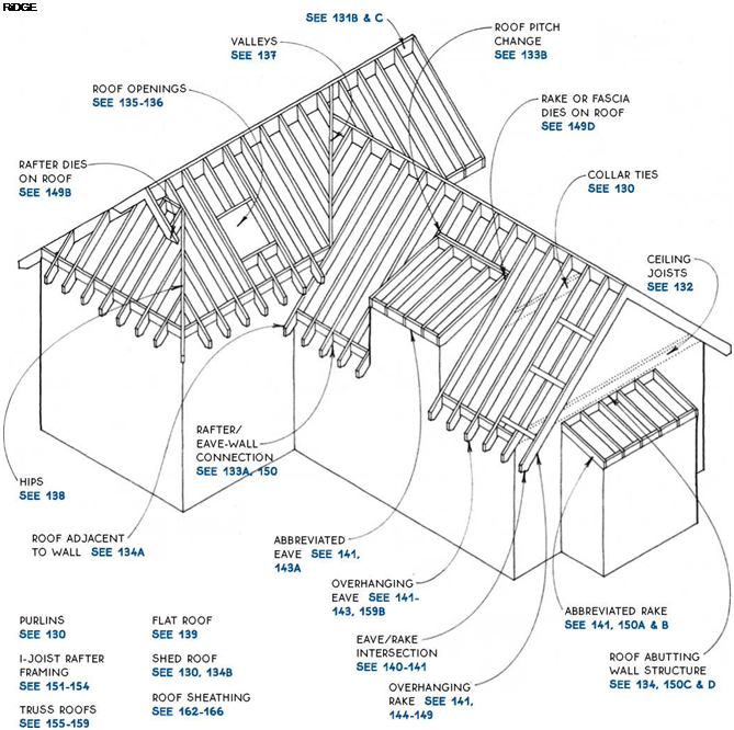
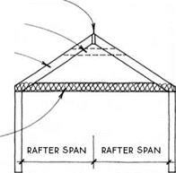
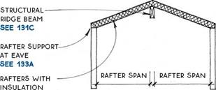
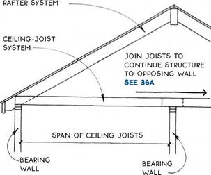
Stick-framed rafters may be supported by the walls of the building, by a structural ridge beam, or by purlins. Simple-span roof – The simplest sloped roof—the shed roof—has rafters that span from one wall to another, as shown at right. These rafters must be strong enough to cany the dead-load weight of the roof itself and subsequent layers of reroofing, plus the live-load weight of snow. The rafters must usually be deep enough to contain adequate insulation. The total roof load is transferred to the ends of the rafters, where it is supported by the walls. In the simple example at right, each wall carries part of the roof load. Triangulated roof – Common (full-length) rafters are paired and usually joined to a ridge board, as shown in the drawing at right. Each rafter spans only half the distance between the two walls (the gable roof, shown in the drawing at right, is the simplest version). Horizontal ties—either ceiling joists or collar ties— form a triangle with the rafters. Ceiling joists are generally located on the top plate of the walls but may also be located higher to form a partially vaulted ceiling. Collar ties are usually nailed near the top of the roof between opposing rafters and spaced at 4 ft. o. c. Collar ties are not sufficient by themselves to resist the outward thrust of the rafters. Rafters in triangulated roofs are shallower than those in shed roofs of equal width because they span only half the distance of the shed rafters and because they do not usually contain insulation. Structural ridge beam—The horizontal ties that are required in a triangulated roof may be avoided if the rafters are attached at the ridge to a structural ridge beam (or a wall), which effectively changes the triangulated roof into two simple-span roofs, as shown in the drawing below.
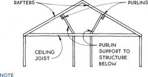
NONSTRUCTURAL RiDGE BOARD SEE 133B COLLAR TiE RAFTER Purlin—A purlin is a horizontal member that supports several rafters—usually at midspan. Purlins were commonly used to help support the long slender rafters of pioneer houses and barns. Today they are also used occasionally to reduce the span of a set of rafters, but the purlins must themselves be supported by the frame of the structure, as shown in the drawing below.
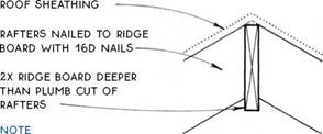
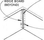
This table compares two species of sawn lumber and one I-joist for use as rafters on a roof with a 30-psf live load. The table is for estimating purposes only. For a roof-sheathing span table, see 163. RIP RiDGE BOARD iF iNTERiOR finish meets Common Rafters AT RIDGE. slightly undercut the plumb CUT ON BARGE OR VERGE RAFTERS IF LuMBER IS GREEN; THE BoARDS will shrink to MEET at centerline.
NAIL iNTo RiDGE BoARD NEAR BoTToM of RAFTERS; uPPER NAILS MAY BE ADDED AFTER lumber DRIES. Ceiling joists are very similar to floor joists. In fact, the second-floor joists of a two-story building act as the ceiling joists for the story below. Ceiling joists are distinguished from floor joists only when there is no floor (except an attic floor) above the joists. Ceiling joists are sized like floor joists. The span of the joists depends on spacing and whether the attic above the joists will be used for storage.
This table is based on a light attic load of 20 psf and a deflection of L/360. The table is for estimating purposes only. The joists can function as ties to resist the lateral forces of rafters. For this purpose, it is important to attach the joists securely to the rafters.
The underside of ceiling joists is often furred down with a layer of 1x lumber to resist plaster or drywall cracking due to movement of the joists. The drawing below illustrates furring parallel to the joists to resist cracking along a beam that interrupts the continuity of the joists. Furring perpendicular to the joists, usually called strapping, is also common.
The width of the bird’s mouth is equal to the width of the sheathed stud wall (or unsheathed wall if sheathing is to be applied later). The underside of the rafters should meet the inside corner of the top of the wall. This is especially important if the ceiling is vaulted and a smooth transition between wall and ceiling is desired (see below). BLOCKING pREVENTS rotation of rafters & allows ventilation of roof. note for rafter support at rake WALL, SEE 1340. Wherever the pitch of a roof changes from shallow to steep (as in a gambrel roof) or from steep to shallow (as in a shed dormer) the two ends of the rafters must be supported. If the pitch change occurs over a wall, the wall itself will provide the support. If the pitch change does not occur over a wall, the support will have to be provided by a purlin or a beam (header).
Pitch Changes with Support Below DouBLE 2X HEADER up-slope RAFTER on joist hanger – – FINISH CEILING
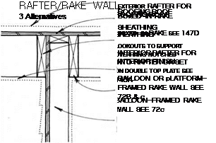
Pitch Changes without Support Below The end rafters of a gable or a shed roof are supported by the walls under them, called rake walls. The framing of the rake should be coordinated with the detailing of the rake. Of the three drawings below, the first example is the simplest method of support and is used with all types of rake, often in conjunction with an unfinished attic. The second example is best for supporting lookouts for an exposed or boxed-in rake. The third example provides nailing for a boxed-in rake or an exposed ceiling. Elements from the three examples may be combined differently for specific situations. For rake-wall framing, see 72A, B & C. ROOFiNG ROOF SHEATHiNG RAKE TRiM SEE 146-147 END Rafter Balloon OR
platform-framed rake wall SEE 72B
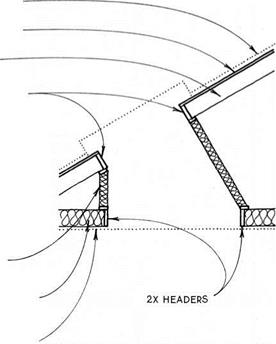
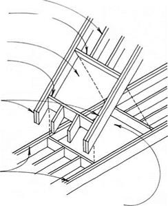
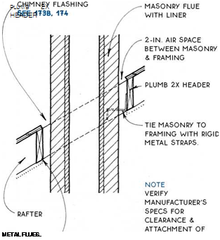
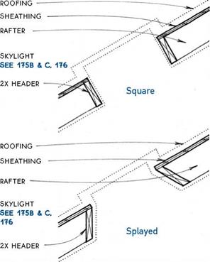
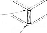
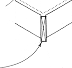
For openings in a single roof plane framed entirely with common rafters, framing is relatively easy. An opening three rafter spaces wide or less can be made by heading off the interrupted rafters and doubling the side rafters, as shown below. Obviously, it is more efficient if the width and placement of the opening correspond to the rafter spacing. Larger openings should be engineered. Openings that straddle hips, valleys, or pitch changes must have special support, special framing, and special flashing. RiDGE DOUBLED COMMON RAFTER AT SiDES OF OPENiNG TOP & BOTTOM RAFTER HEADER (OFTEN DOUBLED) Headers for simple openings are, in most cases, either plumb or perpendicular to the rafters, as shown in the drawing below. Plumb openings require a header deeper than the rafters.
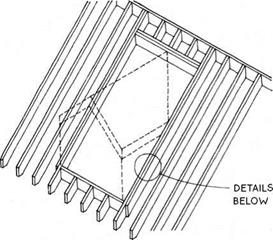
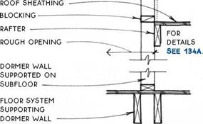
Dormers are often more than three rafter spaces wide so their structure cannot be calculated by rules of thumb. The opening in the roof may be structured to support all or part of the loads imposed by the dormer. The dormer walls and roof are framed like the walls
If the dormer walls do not extend below ceiling level, the roof structure at the edge of the opening must support the dormer. DORMER WALL SUPPORTED ON ROOF FRAMING ROOF SHEATHING ENGINEERED RAFTERS AT SIDE OF DORMER OPENiNG ■ "" If the dormer has side wails that extend to the floor, the floor may be used to support the dormer, and the rafters at the side of the opening may be single.
ROOFiNG SHEATHiNG RAFTER
SKYLiGHT SEE 175B & C, 176 iNSULATED stud wall between roof rough opENiNG & OEiLiNG RouGH opENiNG LiNE oF FiNiSH OEiLiNG
дЛ SKYLIGHT OPENING
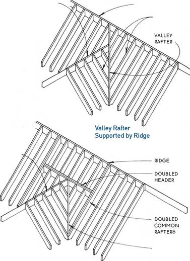
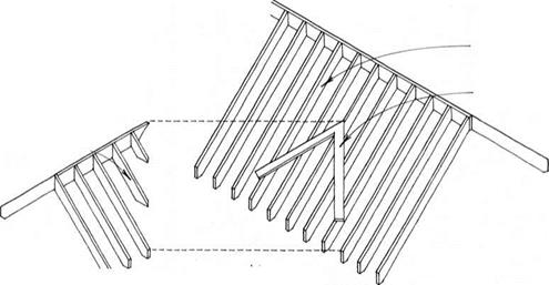
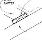
The inside corner of two intersecting roof planes is called a valley. In most cases, valleys are supported by a valley rafter that extends from the outside wall of the building to the ridge or to a header. These valley rafters support large loads and should be engineered. Jack rafters support the area between the valley rafter and the ridge or header. TOP EDGE OF JACK FAFTERS ALiGN WiTH CENTER OF VALLEY RAFTER. bottom edge of valley rafter must be flush with bottom of jack rafters WHEN interior surface is to be finished or it may project below jacks when no interior finish is required, or if jack rafters are furred. As shown at right, valley rafters can be supported at the top by a ridge or by a header. The ridge support system is more practical when the ridges of the intersecting roofs are close together; however, the header support system is better when the lower ridge intersects the main roof near or below the center of the rafter span. Where headroom is not required between intersecting roofs, a simpler “farmer’s valley” or “California valley” may be constructed. This valley is made without a valley rafter. One roof is first built entirely of common rafters without any special valley framing. Then 2x sleepers are installed over the rafters or over the sheathing of the first roof, and jack rafters are attached to the sleepers.
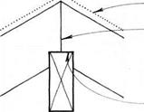
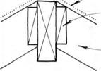
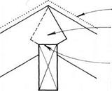
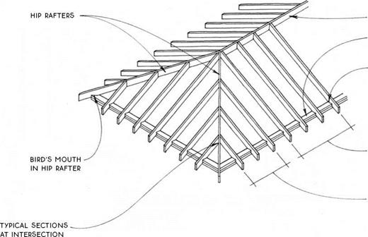
A hip is the outside comer where two planes of a roof meet. It is composed of a hip rafter at the comer and jack rafters from the hip to the eave. The hip rafter is supported at its lower end by the wall at plate level (or by a post) and at its upper end by the ridge (or by a wall). Most codes require that the hip rafter project below the bottom edge of the jack rafters (see the top drawing at right). This is not veiy logical because, unlike a valley rafter, a hip rafter does not support much roof load. The extra depth presents no problem in an attic space, but if the inside face of the roof is to be made into a finish ceiling, the hip rafter will have to be ripped to allow the planes of the finish ceiling to meet (middle drawing at right). If codes will not permit ripping the hip rafter, furring may be added to the underside of the jack and common rafters to allow the finish ceiling to clear the hip rafter. The top ends of the jack rafters may be cut off to permit venting at the top of the hip roof (bottom drawing at right).
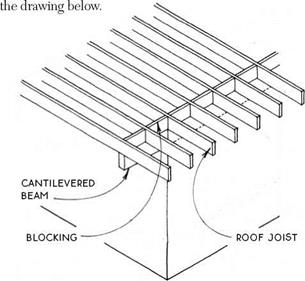
The framing of a flat roof is more like a floor than it is like a pitched roof. The joists are level or nearly level and support the ceiling below and the live loads above. Connections to walls are like those for floors (see 32), as are the framing details for openings (see 38B) and cantilevers (see 39A). As for floors, the structure of a flat roof may be a joist system (dimension lumber or I-joists), a girder system, or a truss system. Blocking and bridging (see 38A) must be considered at the appropriate locations. Flat roofs are unlike floors, however, in that they are not really flat. They might be more properly called “low – slope” roofs because they must slope at least Vi in. per ft. in order to eliminate standing water. This minimal slope may be achieved in several ways: 1. The joists themselves may slope if the ceiling below does not have to be level, or if the ceiling is furred to level. 2. Trusses may be manufactured with a built-in slope. 3. Shims may be added to the top of the joists. 4. Tapered rigid insulation may be added to the top of the sheathing. 5. The joists may be oversize and tapered on top. 6. Sloped rafters can be scabbed alongside level ceiling joists. The easiest and most direct way to support an overhang at the corner of a flat roof is with a beam below the joists cantilevered from the top of a bearing wall, as shown in
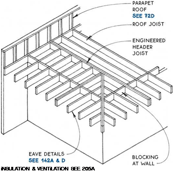
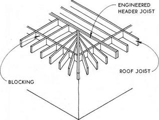
A traditional framing method for a cantilevered corner without a beam is with joists that radiate from a doubled central diagonal joist, as shown below. A strong fascia board is advisable here, as with all framing using cantilevered joists.
A third option for framing a cantilevered comer is shown below. All methods illustrated should be engineered by a professional. NOTE USE RAFTER-SPAN TABLE FOR FLAT-FOOR JOiST SPANS, SEE 131A. Designing the basic shape of the roof and designing the configuration of eaves and rakes are the most critical tasks in roof design. Stylistically, the selection of eave and rake types should complement both the roof form and the roofing material.
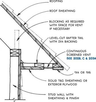
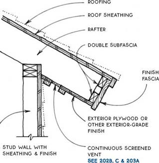
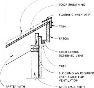
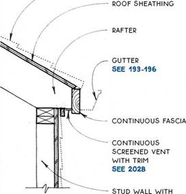
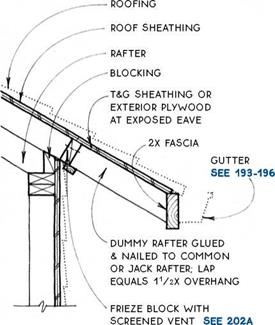
Eave— The eave is the level connection between the roof and the wall. Eaves are common to all sloped roofs and often to flat roofs. There are four basic types of eave (see 141). For eave details, see 142 and 143A & B. Rake- The rake is the sloped connection between the roof and the wall. Only shed and gable roof types and their derivatives have a rake. There are three basic types of rake (see 141). For rake support and rake details, see 144-147. The way in which one edge of a The basic shape and structure of a roof system need to be coordinated with the finish of the roof at the edges. The shape of the roof affects the treatment of the edges, and vice versa. A hip roof, for example, is easier to finish with a soffited eave than is a gable roof. The basic roof shapes are best suited for the following finish treatment at the edges:
^ ROOF SHAPE & EAVE/RAKE SELECTION roof is finished affects the detailing of the other edges. For example, a soffited eave on a gable-roofed building is easier to build with an abbreviated rake than with an exposed rake. The designer should attempt to match the level edge of the roof (the eave) to the sloped edge (the rake). In examining the details of the eave and rake, therefore, the two must be considered as a set. It is logical to start with the eave, because all sloped roof types have eaves, but not all have rakes. There are four basic sloped-roof eave types. All four types are appropriate for hip roofs, and all but the sof – fited type can make a simple and elegant transition from eave to rake on gable and shed roofs. The eave types and their most appropriate companion rakes are diagrammed below.
NOTE THiS DETAiL WORKS WELL ON STEEP ROOFS, WHERE A FASCiA MAY APPEAR TOO BULKY. NOTE no gutter shown. hang gutter from strap SEE 1950 OR USE VERTiCAL FASCiA ON PLUMB-CUT RAFTERS TO ACCOMMODATE STANDARD GUTTERS.
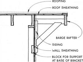
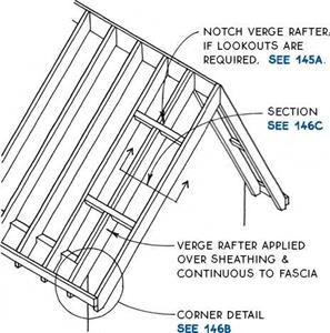
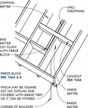
When an overhang is required at the rake, the overhang is made with barge rafters, which stand away from the building and need support. There are several ways to support barge rafters. The roof sheathing alone may be strong enough to support the barge rafters (see 144B), or the ridge board or beam can be designed to support the barge rafters at their upper ends (see 144C), and the fascia may be extended to support the barge rafters at their lower ends (see below). Lookouts or brackets may be also used to support an overhanging rake (see 145A & B). NOTE VERGE RAFTER NOT SHOWN; FOR Details SEE 146. stud wall under end common rafter
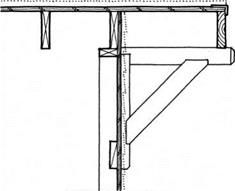
FiRST COMMON RAFTER END OR VERGE RAFTER Brackets attached to the face of the wall framing can support the barge rafter by means of triangulation. nails Attaching the bracket to the inside of the barge rafter avoids problems of weathering.
The alternative bracket connection to the barge rafter shown below is common on Craftsman-style buildings. With this detail, moisture collects on top of the bracket, and this contributes to the decay of the bracket and the barge rafter.
NOTES EXPOSED ROOF SHEATHiNG MUST BE EXTERiOR-RATED PANEL OR SOLiD (T&G) MATERiAL.
Mixture Production in an Asphalt PlantWhen storing a finished, hot mixture in a silo, the mixture closest to the walls of the container is subject to gradual cooling. As storage time increases, the amount of cool mixture is likely to rise substantially. If the SMA contains modified binder, its stiffening process proceeds much faster. Moreover, we may face additional trouble with cool mixture stuck to the walls of the silo unless the silo is heated. Also, if the silo chutes are not heated, problems with discharging the mixture out of the silo can occur. ЕРА Takes a "Stand" on the Carpet ControversyIn October 1987, the EPA installed carpet at its headquarters in the Waterside Mall in Washington, DC. A total of 1,141 complaints were received regarding adverse health effects related to the new carpet.3 These complaints included decreased short-term memory, loss of concentration, confusion, anxiety, headaches, joint and muscle pains, rashes, digestive disorders, reproductive abnormalities, asthma, insomnia, chronic fatigue, and multiple chemical sensitivities. Dozens of workers remained permanently disabled. After the EPA investigated these carpet complaints from its headquarters building, it published a report showing a positive correlation between the EPA worker complaints and the new carpet.6 Despite the results of its own study, and the removal of 27,000 square yards of carpet from the headquarters building in 1989, the EPA published a public information brochure that stated, "Limited research to date has found no links between adverse health effects and the levels of chemicals emitted by new carpet."c Several different adhesives for carpeting (refer to manufacturer) • Envirotec Health Guard Seaming Tapes: Several different seaming tapes for carpeting (refer to manufacturer) • Hendricksen Naturlich Manufacturer’s Adhesive Carpet Treatment Tire following carpet treatment will help remove pesticides, formaldehyde, and other chemicals from the carpeting and pad and will seal in chemicals to prevent outgassing: AFM SafeChoice Carpet Shampoo, AFM EPA’s Director of Health and Safety told the Washington Times that "the freshly manufactured carpet clearly caused the initial illness." Within a few weeks of making that statement he was removed from his job. EPA management expressed concern that testing and regulation of carpet emissions could potentially cost the carpet industry billions of dollars.6 Discussion The Consumer Product Safety Commission (CPSC) has received hundreds of complaints about carpets causing respiratory and neurological problems.6 Toxic emissions from carpets include fumes from formaldehyde, benzene, xylene, toluene, butadiene, styrene, and 4-phenylcyclohexene (4PC). These chemicals can potentially cause cancer, birth defects, reproductive disorders, respiratory problems, and neurological damage such as anxiety, depression, inability to concentrate, confusion, short-term memory loss, and seizures. In spite of overwhelming evidence to the contrary, SafeChoice Carpet Seal, and AFM Safe – Choice Lock-Out. Follow the manufacturers instructions. Test a small sample of carpet with these products for shrinkage and color fastness prior to full application. The treatment is not suitable for carpets with a large wool or cotton content because the wet application can cause shrinkage. Paints, stains, and sealers are all wet-applied finish materials that will have a significant impact on indoor air quality as they are drying. the carpet industry has consistently denied adverse health effects of carpeting. In 1992, in response to public concern, the carpet industry announced its GreenTag program, which has lured consumers into a false sense of safety. The program tests only a small sampling of carpets once a year. The testing is based only on volatile organic compound emissions, not biological health effects/ In fact, some carpets from the Green Tag program tested at the Anderson Labs have caused death to the mice exposed to their fumes.9 a. Bill Hirzy. "Chronology: EPA and Its Professionals: Union Involvement with Carpet." 1992. Cited in "Carpet: Trouble Underfoot." Informed Consent. November/December 1993,p. 31. b. US Environmental Protection Agency. "Indoor Air Quality and New Carpet: What You Should Know." EPA/560/2-91/003. US Government Printing Office, March 1992. c. Bill Hirzy."Chronology: EPA and Its Professionals: Once thoroughly cured, they will no longer release VOCs. While some materials will have very low odor and/or will dry almost instantly, others may be odorous for months. Because of the large surface area that these materials cover, their impact can be significant and they must be carefully chosen. Consider the following: і. Performance: A product that is more durable will not need to be reapplied as often. A product that is more odorous initially but has time to completely cure during the construction period may well be worth considering if it is more durable than the Union Involvement with Carpet." 1992. Cited in "Carpet:Trouble Underfoot Unformed Consent. November/December 1993, p. 31. d. Susan E. Womble. "Evaluation of Complaints Associated with the Installation of New Carpet." Memorandum, Consumer Products Safety Commission (CPSC) Chemical Hazards Program, August 13,1990. e. Ibid. f. Carpet and Rug Institute. "Carpet Industry Program Steps Out Front on Indoor Air Quality: Labeling for Consumers Now Underway." Press release, July 17,1992. g. Anderson Laboratories."Carpet Off-gassing and Lethal Effects on Mice." Press release, August 18, 1992. alternatives. However, adequate ventilation for the construction team during the curing period must be included in this strategy. 2. Application Procedure: Manufacturers instructions must be strictly followed. If applications are not sufficiently dried between coatings, they may remain tacky and odorous indefinitely. This same problem can occur if underlying joint compounds or plasters are not sufficiently cured. 3. Construction Protocol: Good ventilation during the application of wet products will not only speed drying time but will also (along with the use of recommended safety gear) help assure the well-being of the construction team. Furthermore, good ventilation at the time of application will reduce the impact of these odors on porous materials that can acquire odor easily Planning for and specifying a flush-out period at the end of all construction is a good way to allow outgassing prior to occupancy. Where weather permits, fans can be used with open windows to speed this process. Air filters and ventilation equipment may help during inclement weather. 4. Factory applied finishes: Some materials come with an optional factory-applied prefinish. Wood, bamboo and cork flooring, and ceramic tiles are some examples of materials that are commonly offered prefinished or unfinished. Factories often have facilities for safely and fully curing the finishes before the products are shipped out. These factory-applied finishes are often more durable than the lower-VOC finishes that would be suitable for onsite application. Prior to approving a factory – applied finish it is prudent to have a dated sample sent to you to examine along with an MSDS. On occasion, samples may still have persistent odors or the MSDS may reveal the use of unacceptable toxins. Because paints cover such large surface areas, careful selection is crucial. Paints are commonly a source of indoor air pollution. Certain paints and coatings, on the other hand, can improve indoor air quality by sealing out odors in subsurfaces so that they do not out – gas into the living space. All paints and wet-applied coatings have three major components: pigment, binder, and carrier, also known as the vehicle. Water – based (latex) paints use water as the carrier whereas oil-based (alkyd) paints use a variety of much more volatile solvents as the carrier. In the past, oil-based paints were considered to be more enduring than latex paints. However, with recent improvements in latex paint technology, oil-based paints can be entirely eliminated from residential construction. Among the thousands of latex paints available, there is a wide range of volatility, toxicity, and performance. Since the previous edition of this book was published, many more low – to zero-VOC water-based paints have become available from commercial manufacturers. In addition, some of the original commercial ‘environmental paint” products have been reformulated for higher performance in the areas of hide ability, wearability, and scrubability. Low VOC is not the only measure of a paints effect on human health. Both synthetic binders and various additives can cause negative reactions for some people, and paints often contain substances that are environmentally undesirable. Finding out about the presence of these ingredients can be challenging. Additives such as biocides are often proprietary or are present in such small amounts that they are not required to be listed on an MSDS. Several independent nonprofit organizations have arisen internationally to set environmental standards for consumer products. Green Seal is a US-based organization that has created evaluation standards for architectural coatings that have low-VOC emissions and exclude five heavy metals and 21 toxic organic compounds. The commercially available paints listed below have, according to the manufacturers, met these Green Seal criteria. A more extensive list can be obtained through Green Seal. Individuals with chemical sensitivities should test paints to determine the best choice for them. Our experience has shown that sensitivities vary and that none of the paints has a perfect track record with everyone. In some cases, paints with acrylic rather than vinyl or vinyl acrylic binders have been better tolerated. Below are several low – to zero-VOC content paints that you may wish to consider for your project. Commercially Available Interior Zero – and Low-VOC Paints from Conventional Manufacturers Following are widely distributed low emission paints. Please note that the product names shown in bold type are the paint line being recommended for each manufacturer. These manufacturers also make paint lines that we do not recommend. • Air Care Odorless: Solvent-free eggshell and flat by Coronado Paints • American Pride 100 Line: Green Seal certified zero-VOC paints by Southern Diversified Products • E Coat and Enviro-Cote: Paints by Kelly – Mo ore • Enviro-Pure: Green Seal certified zero – VOC paints by M. A. Bruder & Sons • Genesis Odor Free: Paints by Duron • Harmony: Paints by Sherwin Williams • Lifemaster 2000: Paints by ICI Dulux/ Glidden • Premium Interior Paint Zero VOC: Green Seal certified zero-VOC paints by Olympic • Pristine Eco Spec: Green Seal certified paints by Benjamin Moore • Yolo Colorhouse: Green Seal certified zero-VOC interior paints by Yolo Color – house. • Z-coat (59-Line): Green Seal certified zero – VOC interior paints by General Paint Specially Formulated Paints from Alternative Manufacturers Although generally more expensive, the following paints have been specially formulated and often better meet the needs of chemically sensitive individuals: • AFM SafeCoat Enamel Low VOC and Safecoat Zero VOC: Formulated with propylene glycol instead of ethylene glycol and free of ammonia, acetone, formaldehyde, and masking agents • Ecological: Odorless, formaldehyde-free, water-based terpolymer paint • Enviro Safe: No fungicides, low-biocide, and custom mixed to order • Miller Aero: Specify low-biocide, nofungicide • Murco GF1000 and Murco LE1000: No fungicides and only “in-can” preservatives that enhance shelf life but become entombed in the dry paint Paints Derived from Natural Sources The following paints, which are derived from natural sources, contain few or no petrochemically derived ingredients and maybe more environmentally sound choices. Some may not be suitable for the chemically sensitive. Products that contain d-limonene may have vapors that are more toxic than those of petroleum distillates or turpentine and should be used with proper ventilation.1 They are often harder to work with, but when skillfully used can render a more lively wall surface: • AGLAIA Natural Paints: Plant-based natural paint products, free of petrochemicals and artificial resins • Auro Natural Paints: Made exclusively from natural sources by Sinan Co., with efforts made to support ecological diversity • BioShield Clay Paint #12: Zero-VOC paint made from naturally occurring clays • BioShield Solvent Free Wall Paint and BioShield Casein Milk Paint: Very low VOCs, made from natural or minimally toxic synthetic materials • Green Planet Paints: Zero-VOC clay – based paints utilizing soy resin and mineral pigments • Livos Naturals: Low-toxic paints, all ingredients listed on label, many organically grown; both water – and oil-based products available • Milk Paint: Made from milk protein, lime, earth pigments, and clay, petrochemical – free, biodegradable, nontoxic, odorless when dry; not recommended for damp locations because it is susceptible to mildew. Milk paint can sour in liquid form. Comes in powder form in 16 colors (see Clear Coat as recommended topcoat). • Minerva Finishes: Line of all-natural lime-based paints for interior and exterior applications (refer to product literature for specific application and use) • Sinan Company: Several natural water – based and casein-based paints (refer to Resource List for various products) Vapor Retardant Paints The following paints are vapor retarders that can be used to block unwanted outgassing from vapors found in a material: • 86001 Seal: A clear, water-reducible primer sealer and vapor retarder • AFM Safecoat New Wallboard Prime – coat HPV: Specially formulated to cover the uneven porosity of new gypsum board and other surfaces with a high recycled content • AFM Safecoat Transitional Primer: For use on various previously treated surfaces; seals and reduces outgassing • BIN Primer Sealer: A white pigmented shellac sealer used as an undercoat/primer/ sealer, free of biocides, effectively seals in odors from drywall, and should be used in a well-ventilated space since the alcohol base is strong smelling during application (available through most paint and hardware stores) Stains and Transparent Finishes Many standard sealers for wood are solvent – based and contain several highly toxic chemicals that outgas for long periods after application. Several more healthful water-based products are now available. Since water-based products tend to raise the grain on wood or absorb unevenly, many installers who are inexperienced with their use have been disappointed with the results. We have found several good installers who have overcome their initial reluctance and now insist on using less – toxic, water-based products, knowing that in doing so they are safeguarding themselves, their employees, and their clients. Natural, more healthful oils, lacquers, shellacs, and waxes are also available. Clear-Seal Water-Reducible Wood Finishes • AFM Safecoat AcriGlaze: Clear mixing medium and finish, ideal for restoring old finishes, sealing, and preserving painted work • AFM Safecoat Hard Seal: Used in conjunction with AFM Safecoat Lock-In New Wood Sealer • AgriStain: Bio-based interior and exterior stain for metal, wood, gypsum, and cement • Aqua-Zar: Water-based nonyellowing polyurethane in satin or gloss finish • Clear Coat: Nontoxic acrylic coating for use over painted and wood surfaces; may be used in conjunction with Extra-Bond, which will promote adhesion on surfaces other than bare wood • Hydrocote Hydroshield Plus: Water – based polyurethane for interior and exterior use • Zip-Guard Environmental Wood Finish: Clear finish for interior woodwork (the same company makes a product called Zip-Guard, which is solvent based) Natural Oil, Lacquer, and Shellac Wood Finishes • AFM Naturals Clear Penetrating Oil: Plant-based sealer for interior and exterior wood applications • AFM Naturals Oil Wax Finish: Plant – based hardener and sealer for unfinished wood, bamboo, and cork • Auro No. 123 Natural Finishing Oil: Oil primer, sealer, and protective treatment • Auro No. 143 Organic Linseed Oil Finish: Interior and exterior penetrating, protective, and conditioning treatment for wood • Auro No. 251 Clear-Coat Paint Glossy: Oil-based transparent finishing lacquer for use on indoor surfaces; can be tinted • BioShield Primer Oil #1: An oil-based sealer that creates an elastic and breathable grain-enhancing prime coat for priming and sealing hardwoods and softwoods • BioShield Resin Floor Finish #4: Breathable and elastic finish that will create depth and dimension in flooring substrates of all types • BioShield Penetrating Sealer #5: Crafted from linseed oil, plants, and other less hazardous materials, a high-solids primer that excels at sealing cork, dry and absorbent woods, slate, stone, and brick • BioShield Hard Oil #9: Specially recommended for high-moisture and high- traffic areas, this is one of the most durable low-VOC oils suitable for hard and softwood floors • Block Oil: Natural finish for any wooden food preparation surface; may be used to treat any unsealed interior wood surface • Sinan Company No. 143 Linseed Oil: Organically grown, for plain oiled-rubbed finish • Sinan Company No. 251 Natural Clear Varnish, Clear, Glossy: Clear, Glossy #251 or Clear, Satin #261 varnish with good covering qualities for indoor wood use only • Sinan Company No. 253 Natural Undercoat Enamel, White, Water-Based: Suitable for priming or intermediate coats for interior and exterior use on wood • Sinan Company No. 260 Natural Enamel, White, Water-Based, Interior, Satin: Low-gloss lacquer for interior use only, to be used after one undercoat of No. 253; can be tinted Wood Stains • AFM Safecoat Durostain: Interior and exterior • BioShield Aqua Resin Stain: Zero-VOC, resilient wood stain finish for interior and exterior applications • BioShield Earth Pigments #88 • Hydrocote Danish Oil Finish: Stain that colors and protects in one step • Livos Kaldet Stain, Resin & Oil Finish: Satin, semi-flat, water-resistant finish, interior and exterior, strong surface hardening capacity for wood cabinets, doors, and windows • OS Color One Coat Only: Natural oil- based stains • PureColor: Two-stage stain formulation of pure mineral ions and oxygen catalyst with no solvents, oils, VOCs, odors, acids, or bleaches Clear Vapor-Barrier Sealants for Wood These products are used to help lock in noxious fumes so they do not escape into the air. In fact, since no seal is ever perfect, vapor – barrier sealants generally serve to decrease the amount of outgassing at any one time while increasing the overall time it takes for any substance to completely volatilize. We recommend that all efforts be made to speed up the outgassing time prior to application of vapor barrier sealants. Outgassing can be accelerated by using filtration or adsorbers indoors or by doing the application outdoors in a weather-protected area whenever possible. VOCs readily release noxious vapors in heat. Harmful chemicals can thus be dissipated more quickly if they are exposed to elevated temperatures. This can work well in controlled factory conditions but is not recommended for products in the home. Adsorbers are substances such as zeolite or aluminum silicate to which VOCs adhere. When adsorbers are placed in a room, they help remove VOCs from the ambient air. Although most coatings seal to some degree, and will be more effective when applied in several layers, the following products are advertised by their manufacturer as recommended specifically for locking in noxious fumes. The manufacturer s instructions for application must be followed in order to achieve an optimum seal. • AFM Safecoat Hard Seal: Clear sealer for low-moisture areas • AFM Safecoat Safe Seal: Clear sealer for porous surfaces; also an effective primer Anderson Laboratories, PO Box 323, West Hartford, VT 05064,802-295-7344, For evaluation of toxic effects of selected carpets, insulation, and other building materials through testing on mice. Consultations are available by phone for a fee. Carpet and Indoor Air: What You Should Know. June 1993. Availabl e free of charge from New York State Attorney General, 120 Broadway, New York, NY 10271. Environmental Access Research Network (EARN). 315 W. 7th Avenue, Sisserton, SD 59645. For a list of carpet-related articles, studies, and reports available from EARN’s photocopying service, send $1.00 and request “carpet list.” Foster, Kari et al. Sustainable Residential Interiors. John Wiley and Sons, 2007. A guide to sustainable principles and practices that can be applied to every level of interior design. Guelberth, Cedar Rose and Dan Chiras. The Natural Plaster Book. New Society Publishers, 2003. A step-by-step guide for choosing, mixing, and applying natural plasters. Thrasher, Jack and Alan Broughton. The Poisoning of Our Homes and Workplaces: Tf-ie Indoor Formaldehyde Crisis. Seadora, 1989. Suction/Saturation ControlAlthough there are a wide variety of tests for assessing soils and road materials, any serious investigation will need to know the mechanical behaviour of these materials when subjected to repeated loading that simulates the effects of trafficking and under moisture conditions (water content and suction) that simulate that found in the layers of the road construction and embankment. Various devices have been developed including the k-mould (Semmelink et al., 1997) and the Springbox (Edwards et al., 2004), but the cyclic triaxial test has secured the greatest following for material assessment over many years and is now the subject of European, US and Australian standards (CEN 2004, AASHTO 2000, Standards Australia 1995). It is the use of this test that is described in this section. In laboratory testing procedures it is well known that the size of the sample may have a very important influence on the results. If the size of the sample is not appropriate for a test procedure, the results obtained may be corrupted and not valuable. In order to have a continuum condition in the sample, it is necessary to satisfy some conditions with regard to its microstructure and sample size. For fine soils, it can be assumed that the test sample should be some centimetres in diameter, roughly from 2 to 6 cm. However, for granular materials, the sample diameter should be much higher, from about 5 to 10-15 cm, depending on maximum grain size. Problems of Manufacture and TransportationMost questions related to maintaining a suitable temperature during the mixture’s manufacture have been regulated by commonly known technical specifications (e. g., standards, guidelines). These questions are discussed in Chapter 9. Simply speaking, there are two main problematic instances in the matter of SMA manufacture temperatures—when the temperatures are too low or when the temperatures are too high. Too low a manufacturing temperature of a mix prevents the formation of a correct and complete asphalt binder film. Too low a temperature can be visually recognized; aside from visible uncoated aggregate pieces, the appearance of the mixture seems to be matte. Since SMA contains a considerable amount of binder, it should be glossy and glisten “glow wormly” (namely, like glow worms) at a suitable temperature.[69] Too high a manufacturing temperature increases the threat of binder draindown from the aggregate and excessive aging of the binder. Loading the overheated SMA into a silo runs the risk of getting into trouble with excessive draindown. To check SMA susceptibility to draindown after mixture overheating, one ought to test it when the SMA is at a temperature 15°C (or 25°C) higher than the recommended manufacture temperature (see Chapter 8). |


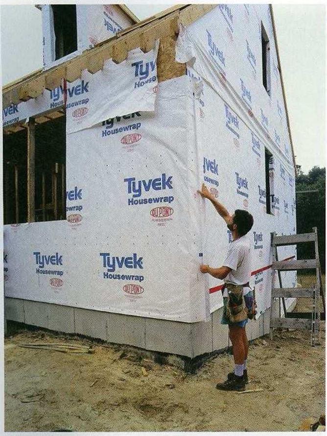
![STEP 1 Seal Penetrations in the Walls, Ceilings, and Floors Подпись: HOUSEWRAP ACTS AS A WATERPROOF WINDBREAKER. Tyvek and other modern housewraps are installed beneath the exterior siding. They block wind and water while still allowing vapor to pass through. [Photo ® Mike Guertin.]](/img/1312/image734_0.gif) not done for some reason, you can run a heavy bead of sealant where the inside edge of the bottom plate meets the subfloor.
not done for some reason, you can run a heavy bead of sealant where the inside edge of the bottom plate meets the subfloor.
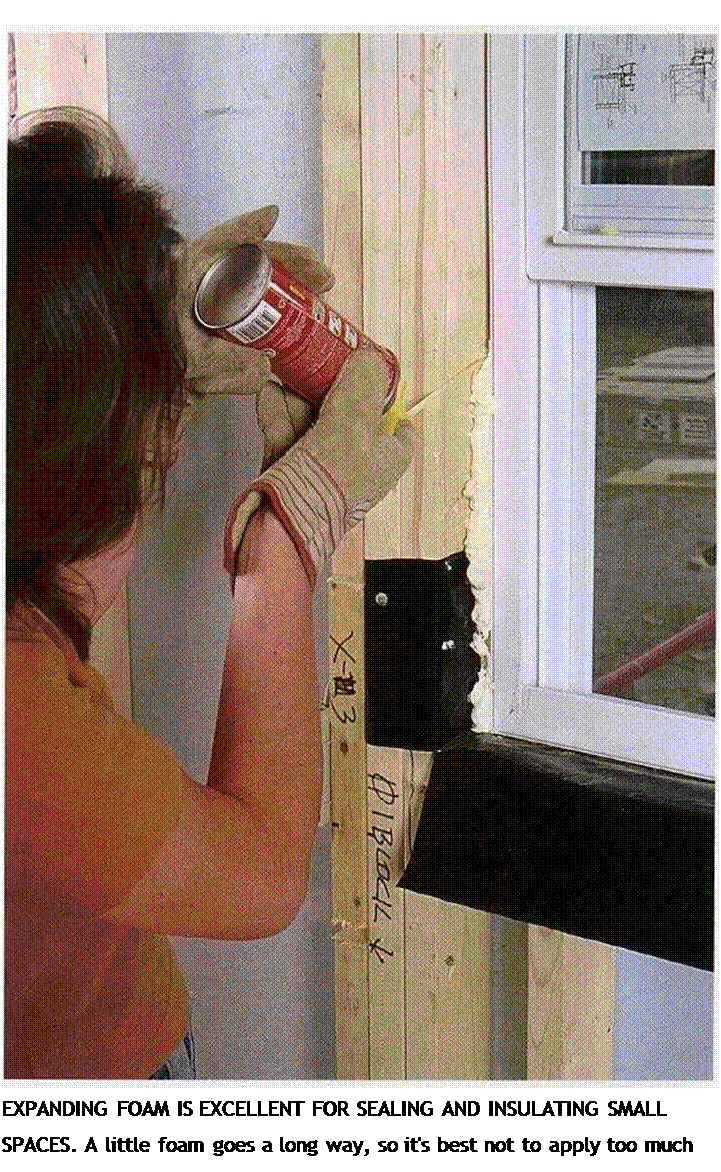
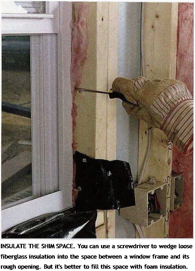 when it is compressed. Its better to insulate narrow spaces with foam insulation. The spaces between the window or door jamb and the rough opening can also be “foamed,” but be careful not to apply too much expanding foam in those areas. Since jambs are usually only}/ in. thick, the foam’s expansive action can cause them to bow inward.
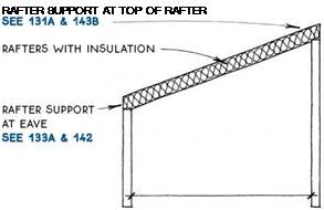




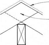


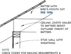
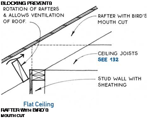

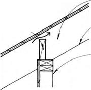

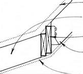 At walls or beams that support them at the eave, rafters are cut at the point of support with a notch called a bird’s mouth.
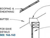
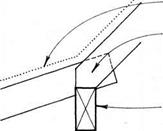
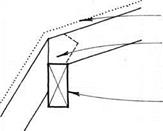

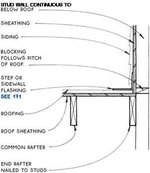
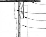
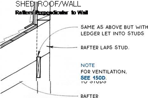
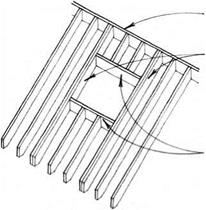
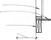 Framing the elements that project through the roof of a building—skylights, chimneys, and dormers— begins with a rectangular opening in the framing.
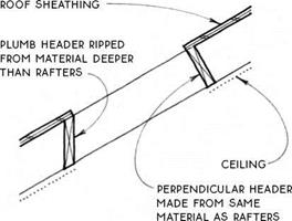



 2X HEADERS





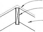

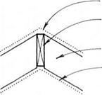



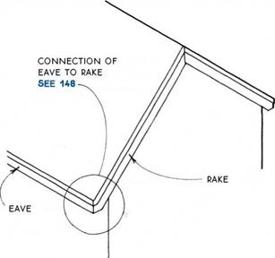

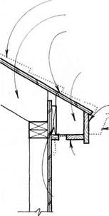
 Functionally, the eave and rake should help protect the building from the elements. The shape of the roof will suggest certain eave and/or rake shapes (see 140B), and certain eave types work best with particular rake types (see 141).


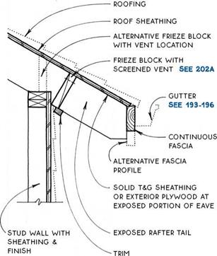
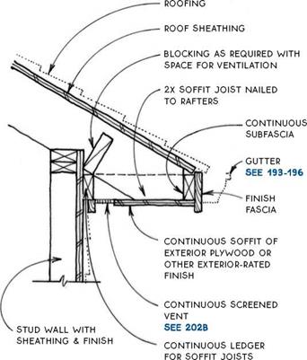





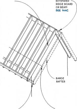
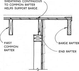


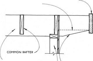


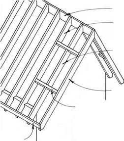


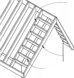

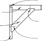 If the ridge, the fascia, and the sheathing together do not provide sufficient support for the barge, lookouts may be added. Lookouts extend from the barge rafter to the first common rafter (or truss) inside the wall. The lookouts are notched through the end rafter at the top of the wall or, alternatively, bear directly on the wall. The size and spacing of lookouts depend on rafter spacing and live loading.
 FOR ALTERNATiVE DETAiL WiTH TRiM BOARD, SEE 147A & B.