Paver-Made Streaks

Let us suppose that an adequately hot mixture is delivered to the job site. Nevertheless, badly adjusted paver elements (in the given examples, badly arranged screed seg­ments) may bring about the formation of porous areas in the course (streaks). Figure 11.13 presents an example of streaks pulled by a paver during laying. Figure 11.14 presents the same effect but photographed with an infrared camera.

11.8.2.1 Paver Standstills

One of the main principles of laying SMA is avoiding a paver standstill. Almost every time the paver is immobile, uncompacted areas behind the machine are the result (Figure 11.15). This effect is heightened if the mixture contains modified binder (higher stiffening of the mixture during cooling down). Figure 11.16a and b presents infrared camera photos of mixture cooling down during a paver standstill.

KITCHEN SINKS

Kitchen sinks require a minimum clear space in front of them that must be 30 inches by 30 inches. This is based on a measurement made from the front face of the kitchen sink, counter, or vanity. Measuring from the finished floor to the top edge of a kitchen sink or counter should result in a measurement of 34 inches, maximum. Unobstructed knee clearance with a minimum of 29 inches high by 8 inches deep should be provided. Toe clearance should be a mini­mum of 9 inches high by 9 inches deep, provided from the sink to the wall.

Additional requirements for a handicap kitchen sink require that all ex­posed hot-water piping be insulated. Faucets should be installed so that they are no more than 25 inches from the front face of the lavatory, counter, or vanity. And, the faucet must be able to be turned on and off with a maximum force of five pounds.

Examples of Test Results

10.4.1 Laboratory Results

Wetting of unsaturated soil reduces the suction in the soil, the pore pressure ap­proaches the pore air pressure and the effective stress is reduced. Because of this, increasing moisture is associated with decreases in shear strength, stiffness and re­sistance to plastic deformation in all soils and aggregates and we can observe a decrease in bearing capacity and lower moduli of elasticity and increases in de – formability under the same applied loading.

10.4.1.1 CBR Tests

This influence of moisture on the bearing capacity of soils can be easily observed in the simple CBR test. This test measures the resistance of the compacted soil to the penetration of a piston, to evaluate its bearing capacity. CBR values for three typical soils related to water content are presented in Fig. 10.8. The sensitivity to moisture variations is particularly important for the silty sand (a).

Decrease of bearing capacity and of unconfined compression strength of clay with increasing water content can also be observed in Fig. 10.9.

The CBR test gives a good indication of the moisture sensitivity of subgrade soils, but its results are only qualitative. The influence of moisture on the resilient modulus and resistance to permanent deformations of soils and unbound granular materials can be studied using repeated load triaxial tests.

Multiple-Support Slip Base-Coupler Designs

Inclined slip base designs, commonly used for single sign supports, cause the sign to rise up upon impact and allow the vehicle to pass beneath the sign. In a multiple-sign- support system, each support is fastened to the other supports by the sign panel and any existing sign panel bracing. When an inclined slip base is used on multiple-support assemblies and only one support is struck, the sign panel stops the impacted support from moving upward. As a result, the slip base can become locked, or the sign panel torn from the other supports, causing intrusion of the panel or support into the vehicle. Inclined slip bases should be used only for multiple-support assemblies when all supports are within 6 ft (1800 mm) of each other. The horizontal slip base (Fig. 7.25) and the frangible coupler (Fig. 7.21) are the most frequently used designs for multiple-support systems. The horizontal slip base design, details of which are shown in Fig. 7.26, operates through separation of the top plate from the anchor plate.

Frangible coupling designs, presented in Fig. 7.27, are designed to effect separation from the anchor plate by fracturing the couplings. Figure 7.27a presents a load con­centration design in which the small cross-sectional area, at the necked-down portion of the coupling, breaks at impact. Figure 7.27b presents a frangible aluminum coupling, by Transpo Industries, designed to break upon impact. The couplings are available in

FIGURE 7.25 Installation of horizontal slip base.

FIGURE 7.28 Base with load concentration couplers.

different sizes, designs, and resistance to fracture. Figure 7.28 presents a frangible coupler application for a large sign support. Notice the low profile of this design. The only portions of the sign assembly above ground level are the frangible couplings, so that the possibility of snagging the vehicle undercarriage is practically eliminated.

Horizontal slip base and coupler designs are intended to safely operate by allowing the vehicle to pass under the sign and support assembly upon impact, as presented in Fig. 7.29. This is accomplished by providing a hinge at least 7 ft (2100 mm) from the bottom anchor plate to allow the support to swing away.

FIGURE 7.29 Illustration of hinge action for large multiple-support sign. (a) Vehicle passes under. (b) Hinge activates. (c) Vehicle impact.

FIGURE 7.30 Common hinge designs used for large multiple supports. (a) Saw-cut support with front plate. (b) Saw-cut support with front plate and rear hinge plate. (c) Saw-cut support with weakened front plate and rear hinge plate.

LAVATORIES

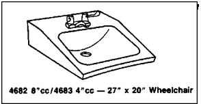
Lavatories installed for handicap use must be of a type that is accessible by a person in a wheelchair (Fig. 10.9). The minimum clear space in front of a lava­tory must be 30 inches by 30 inches. This is based on a measurement made from the front face of the lavatory, counter, or vanity. Measuring from the fin­ished floor to the top edge of a lavatory or counter should result in a meas­urement of 35 inches. How much clearance is required under the lavatory? Unobstructed knee clearance with a minimum of 29 inches high by 8 inches deep should be provided. Toe clearance should be a minimum of 9 inches high by 9 inches deep, provided from the lavatory to the wall.

Additional requirements for a handicap lavatory require that all exposed hot-water piping be insulated. Faucets should be installed so that they are no more than 25 inches from the front face of the lavatory, counter, or vanity. And, the faucet must be able to be turned on and off with a maximum force of five pounds. Now, what happens if the lavatory is installed in a privacy

Подпись:

LAVATORIES

compartment of a toilet? When a lava­tory is installed in a compartment, the lavatory must be located against the back wall, adjacent to the water closet. The edge of the lavatory must have a minimum of 18 inches of clear space, measured from the center of the toilet.

Bearing Capacity Measurements In-Situ

There are many ways of evaluating pavement structural capacity or adequacy and it is very common to perform deflection measurements with non-destructive testing equipment (COST Action 325, 1997). Once again, there is usually no knowledge of the pore pressure or pore suctions in the soil or pavement layer being assessed, so a total stress interpretative framework is necessary even though an effective stress framework would be more desirable.

There are several reasons for deflection measurements to be carried out: for quality assurance, to evaluate the bearing capacity of the unbound material of the granular base, sub-base and subgrade layers, to identify weak parts of the road, to investigate reinforcement requirements, to establish priorities for road strengthening and for research purposes.

Deflection measurements can be performed in various ways, using:

i) static deflection measurement equipment;

ii) automated beam deflection measurement equipment;

iii) dynamic deflection measurement equipment;

iv) deflection instruments with a harmonic load; and

v) deflection measurement equipment with an impulse load.

i) Static devices include: static and dynamic plate loading (bearing) tests and Benkelman beam.

Plate bearing test. This involves measurement of the deflection caused by a known static load applied through a hydraulic jack on the pavement layer surface by a circular plate. Circular plates are of specified diameters -300,450 and 600 mm with loads up to 60 kN. It is a slow and laborious test and needs a heavy vehicle acting as stationary reaction frame against which the hydraulic jack reacts. The plate test device may be mounted inside a van or at the rear of a lorry.

Dynamic plate bearing test. This is performed by lifting and dropping a known load from a known height onto the circular plate and measuring deflections. In this way, the dynamic effect of vehicles to the pavement is simulated.

The two preceding plate bearing tests are generally only used for mea­surement of bearing capacity of unbound layers.

Benkelman beam. This device consists of two main parts: a stand and a beam (Fig. 10.4). One end of the beam rests on the road surface but the other one is connected to a dial test indicator. The beam is suspended on

Fig. 10.4 Benkelman beam: (1) dual tyres of a loaded vehicle, (2) tip of the beam, (3) ball bearing, (4) adjustable support legs, (5) dial test indicator, (6) stand (Tehnicne specifikacije za ceste, TSC 06.630, 2002). Reproduced by permission of Direkcija Republike Slovenije za Ceste

the stand at two thirds of its length from the end being in contact with the road surface. In this way, when this end moves in one direction, the other end moves in the opposite direction half of that movement and it will be measured by dial gauge. The tip of the beam is placed between the dual tyres of a loaded vehicle. The vertical movement of the surface is then recorded as the truck moves slowly away from the loading area as this results in the rebound of the deflection that was caused by the application of the loaded vehicle. The rebound deflection/deflection ratio depends on the condition of the underlying road layers. For example, high water content caused by thawing can result in a relatively low ratio. If the deflection bowl is large, as in the case of weak subgrades, and the supporting legs are placed in the deflection area, this may produce inaccurate measurements.

ii) Automated beam deflection measurement equipment is represented by the Lacroix Deflectograph. It was developed in order to carry out measurements more quickly than by the time-consuming Benkelman beam. The measurement beam is automatically displaced along the measurement direction, while a mea­surement vehicle proceeds at slow speed. Equipment includes a T-shaped frame towed between the axles of lorry, enabling deflection to be measured in both wheel paths simultaneously (Fig. 10.5).

The measurement starts when the rear wheels of lorry are at a certain distance behind the tip of measuring beam and ends when the wheels reach a certain distance in front of it. Then the entire T-frame is moved forward a specified distance in the direction of movement. The axial load can vary from 80 kN to 130 kN.

Fig. 10.5 Deflectograph Lacroix equipment: (1) measuring beam, (2) T frame, (3) starting position of tip of measuring beam, (4) end position of tip of measuring beam (Tehnicne specifikacije za ceste, TSC 06.630, 2002). Reproduced by permission of Direkcija Republike Slovenije za Ceste

iii) Curviameter records the surface deflection under a dynamic load. The vertical displacement is determined in the right-hand wheel path by means of velocity sensors when the loaded twin-wheel rear axle of the measuring lorry passes over. Like the Lacroix deflectograph, loads can vary from 80 kN to 130 kN. The High Speed Deflectograph also belongs to this category. At a driving speed of 80-90 km/h, laser Doppler sensors measure the movement of the pavement surface under a 10-tonne axle.

iv) Deflection measurement by harmonic load can be performed by equipment that can exert a sinusoidal vibration in a road pavement. A well-known example of this type of equipment is the Dynaflect, in which the power is transferred to the road by means of crank at a specified frequency via two steel wheels. The deflections are measured by five geophones spaced at various offsets from the centre of load.

v) Bearing capacity assessment. The most common device to measure bearing capacity of roads is the Falling Weight Deflectometer (FWD). In a FWD test an impulse loading is applied to the pavement which is similar in magnitude and duration to that of a single heavy moving wheel load. The vertical response of the pavement system is measured on the surface with deflection sensors at different distances from the loading. Usually only the peak values are registered, see Fig. 10.6.

Frequently six or seven sensors are used but the spacing between the sensors can vary. Typical values are given in Table 10.1.

The deflections can be used to back-calculate the layer moduli of the structure. This requires information on the number of layers in the pavement structure and

their thicknesses. This is an inverse process where a single, correct solution does not exist. A number of software solutions exist to perform such back-analysis.

The deflections can also be used to estimate some simple parameters which are related to the condition of the pavement, some of the more common ones are:

SCI = D0 – D2 (10.1)

BDI = D2 – D4 (10.2)

BCI = D4 – D5 (10.3)

1 N-1

AREA = (Di – + Di )(n – n_0] (10.4)

D0

where SCI = the Surface Curvature Index, BDI = the Base Damage Index, BCI = the Base Curvature Index and AREA = the area of the deflection basin (all assuming radii as per the light pavement in Table 10.1).

A falling weight deflectometer is mounted on a trailer or in a van, so it needs a stable surface. On soft ground or in trenches the smaller portable light weight FWDs (Fig. 10.7) can be used. These equipments measure the central deflection, resulting in a surface modulus.

Table 10.1 Some typical set-ups for FWD testing

Radial position of falling weight deflectometer sensors

Sensor no. i

0

1

2

3

4

5

6

Radius, light pavement [cm] ri

0

20

30

45

60

90 –

Radius, heavy pavement [cm] ri

0

30

60

90

120

150

210

Data in bottom row taken from Highways Agency (1999).

Deflection Dj is measured at distance rt from centre of the impact of the load.

Identification and Estimation of Model Parameters

A general overview of conventional and some advanced numerical models used in practice has been given in Chapter 9, Section 9.4. Therefore, tests needed for the parameters of these models will now be presented.

• Resilient behaviour models

о Routine pavement design model: in practice much routine pavement design is carried out as catalogue – based design. The pavement is considered as a multi-layered elastic system with constant stiffness parameters in each layer.

о Advanced pavement models: RLT tests are required with variable confining pressure (CEN standard EN 13286-7 (2004)), they correspond to strain sta­bilization. Parameters are determined with curve fitting by the least squares method applied to the equations of the model and to RLT tests results in the stress – elastic strain planes (p, ev) and (q, eq). Both phenomenological models which describe behaviour from an observational standpoint (such as the k—6 and “Universal” Models) as well as theoretically-derived models (such as the Boyce and modified Boyce model) require this kind of testing. The more complex models require VCP test procedures (see Section 10.2.1, above).

• Permanent deformations models

о Analytical models: they require 3 monotonic triaxial tests for the rupture parameters and 3 VCP tests (q /p = 1, 2 and 3 for example) for the plas­ticity parameters. Curve fitting can be used with the least squares method applied to VCP tests results and to the analytical equation of the model

(evertical f(N)) in the plane (N, e^cal).

о Plasticity theory based models

• Bonaquist and Desai models

– Elastic behaviour: the parameters require RLT tests (q /p = 3) at various confining pressures (AASHTO T307-99 (2000)).

– Monotonic plasticity parameters: 3 monotonic triaxial tests till rup­ture for the rupture characteristics and hardening parameters.

– Approximate accelerated analysis: 1 RLT test with one stage at (q /P = 3) is required.

• Chazallon and Hornych model

– Elastic behaviour: RLT tests are required with variable confining pressure (CEN standard EN 13286-7 (2004)), they correspond to strain stabilization.

– Monotonic plasticity parameters: 1 oedometric test, and 3 triaxial tests till rupture are required.

– Cyclic plasticity parameters: 1 RLT test with one stage is required

(q /p = 2).

о Elasto-visco-plastic equivalent models

• Suiker elasto-visco-plastic model

– Elastic behaviour: these parameters are required for the initial state of the material. They require at least 2 monotonic triaxial tests at two different confining pressures when 100 cycles have been per­formed (q / p = 3).

– Monotonic plasticity parameters: they are required for the initial state of the material: 3 monotonic triaxial tests are required.

– Cyclic plasticity parameters: RLT tests (q/p = 3) are required.

о Mayoraz visco-plastic model

– Plasticity parameters require 3 triaxial tests till rupture and a RLT test

(q/p = 3).

о Shakedown models

• Perfectly plastic models

– Elasticity parameters: RLT tests (CEN standard EN 13286-7 (2004)) are required with variable confining pressure till stabilization.

– Plasticity parameters: 3 triaxial monotonic tests till rupture are re­quired.

• Kinematic hardening models

– Elasticity parameters: RLT tests (CEN standard EN 13286-7 (2004)) are required with variable confining pressure till stabilization.

– Plasticity parameters: 3 triaxial monotonic tests till rupture are re­quired for rupture parameters and 3 VCP tests (q /p = 1,2 and 3 for example) with 3 stages for each stress path.

Insulating walls and ceilings with fiberglass batts

The first thing to realize about installing fiber­glass insulation is that you can’t just shove the batts into wall and ceiling cavities any old way and expect them to do their job. Insulation batts must fit snugly between studs or joists and cannot be jammed in tightly or packed loosely and sloppily with gaps all over the place. Kraft paper-faced batts have tabs, which should be stapled to the face of the studs every 12 in. or so.

Many installers staple the tabs to the insides of the studs, which makes it easier to install drywall. However, I don’t recommend this approach. When the paper tabs are sta­pled to the inside of the studs, a slight gap is left along both sides. Gaps are absolutely taboo when you’re installing fiberglass insula­tion because they significantly reduce the insulating value.

If you plan to install fiberglass insulation in warm, humid climates (such as the south­eastern U. S.), buy unfaced batts (see the photo at right). Fiberglass insulation with kraft paper-facing acts as a vapor barrier on the inside of exterior walls, potentially causing moisture problems.

For partial bays (less than 14/ in. or 22/ in. wide between studs) and small spaces, such as over headers and under windows, insulation must be cut to fit. Measure the width and length of smaller bays and cut the insulation about к in. to 1 in. larger (no more!) in each direction so that it will fit snugly in the cavi­ties (see the sidebar on p. 202). You don’t need to staple smaller pieces of insulation in place; the snug fit should hold them until the dry – wall is installed.

While you’re insulating, keep in mind that another property of insulation is sound sup­pression. Given its relatively reasonable cost, you may want to use unfaced insulation in bedroom walls that adjoin a bathroom, living room, or utility room.

Take even more care when insulating the ceiling (see the top photo on p. 203). Any heat that escapes into the attic can cause snow to melt, possibly causing an ice dam on your roof. When insulation batts butt together end to end in the ceiling, make sure the joints are tight.

Because of the importance of keeping heat in the living area and out of the attic, I prefer using blown-in cellulose for the attic, even if the walls are insulated with fiberglass batts. Cellulose settles into and around gaps in the framing, forming what amounts to a giant down comforter over the entire living area of your house. And remember, it doesn’t cost much to add a few more inches of cellulose—

Approved Single Supports for Multiple-Support Assemblies

There are few single-support systems that can be buried directly and provide accept­able multiple-support performance upon impact. Two such systems are dual 3-lb/ft (4.5-kg/m) U-channel and dual 4-in X 4-in (90-mm X 90-mm) shaped wooden posts. The majority of single-support adaptations to multiple-support assemblies require the use of anchor pieces and breakaway designs. Triple supports consisting of 1.75-in X 1.75-in (45-mm X 45-mm) square perforated tube and triple 2.5-lb/ft (3.7-kg/m) U-channel

NOTE:

RECOMMENDEO TORQUE

ON SUP BASE FLANGED

HEAD BOLT & NUT IS 54 Nm

KEEPER

PLATE

760

kzoo-э!

FIGURE 7.23 Acceptable slip base breakaway device for multiple-square-tube sign assemblies. Dimensions shown as mm. Conversions: 200 mm = 8 in, 760 mm = 30 in,

54 N-m = 40 ft-lb.

are acceptable when installed with an anchor and breakaway design. Manufacturers are developing devices that enable the use of heavier supports for acceptable multiple – support systems. Figure 7.23 presents a slip base breakaway assembly for square-tube supports manufactured by Unistrut Corporation, which is acceptable for three 2.5-in X 2.5-in (64-mm X 64-mm) supports within a 7-ft (2100-mm) path [32]. The bottom subassembly is inserted into a 30-in (760-mm) anchor piece and placed in an 8-in-diameter (200-mm), 30-in-deep (760-mm) concrete foundation.

Multiple supports for large signs are often constructed as slip base designs with galvanized steel wide-flange (W) or American Standard (S) shapes for the sign support. These shapes, depicted in Fig. 7.24, are designated by their depth and unit weight or mass. For example, a W150 X 18 is a wide-flange shape with a depth of 6 in (150 mm) and a unit weight (mass) of 12 lb/ft (18 kg/m).

FIGURE 7.24 Examples of rolled-steel shapes for sign supports. (a) Wide-flange (W) shape. (b) American Standard (S) shape.

Multiple-support-sign assemblies that are constructed of W and S shapes are fre­quently designed with frangible or load concentration couplers. The behavior of these designs is similar to slip bases except that, instead of the base slipping from between the bolts, the couplers, which are used in place of the bolts, break at impact.

Control or Measurement of Suction/Moisture

As shown in Chapter 9, Section 9.5, a complete description of a material’s be­haviour necessitates an effective stress approach with the pore pressures (or pore

Number of load pulses Number of load pulses

Fig. 10.3 Typical results from permanent deformation testing where the accumulated axial strain is shown as a function of the number of load pulses in the permanent deformation tests (Erlingsson, 2000) suctions) being separately controlled, or monitored, from the applied pressures. Be­cause most road materials are coarse grained and partially saturated and/or above the ground water table, it usually proves impossible – and certainly it is impractical in most situations – to monitor the pore suctions during each transient pulse. For this reason, almost all testing programs determine parameter values for resilient and incrementally-developed plastic strain models in terms of total, not effective, stresses. Instead, test procedures typically seek to control the moisture or suction conditions so that data is collected at representative conditions.

As described above, unsaturated soils exert an attraction on water, either by cap­illarity in the pores, between grains of the soil, or by the physico-chemical effects. The energy necessary to extract water from the unsaturated soil, for example from a dense compacted swelling clay used for engineering barriers in nuclear waste, can be higher than 10 MPa. However, a granular soil will have a suction that is
several tens of kPa (Delage 2001). The following techniques are commonly used

for suction/moisture control:

i) Axis translation system

This system is based on ceramic low porosity stone, called High Air Entry Value (HAEV) porous stone. The principle of the system is that the pores of the ce­ramic are too small to de-saturate, even when a high air pressure is applied. In other words, the capillary air-water menisci located at the surface of the ceramic can resist an air pressure applied to it, thereby maintaining a continuous water column from stone to specimen. The system has been employed for determi­nation of the water retention curve (i. e. the soil water characteristic curve) (as in the Richards cell) as well as for suction control in oedometer and triaxial testing (Peron et al., 2007; Cuisinier & Laloui, 2004). The retention curve can be determined as follows. A saturated sample should be placed in the cell and the air pressure increased in a step-by-step progression. For a given air pressure, suction equilibrium should be achieved in a time period of a few days (typically 3-10). At the end of equilibrium phase, the sample should be quickly withdrawn and weighed to determine the water content. The sample is then placed into the cell and the air pressure increased to bring about a new equilibrium with a higher suction and lower water content and lower degree of saturation. The process is then repeated as desired.

ii) Osmotic technique

This was initially used by Kassif and Ben Shalom (1971) in an oedometer test to study expansive soils. Several authors extended this technique to a standard triaxial apparatus (Laloui et al., 2006; Komorik et al., 1980; Delage et al., 1987). The technique is based on drainage of the specimen caused by the process of osmosis. The soil sample is placed in a tube-shape cellular semi-permeable mem­brane, which is immersed in an aqueous solution of PolyEthyleneGlycol (PEG). Since the PEG molecules are too big to cross the semi-permeable membrane, the difference between concentration of the PEG solution and that of pore water results in an osmotic pressure. Thus, the suction value depends on the concen­tration of the solution: the higher the concentration of the polyethylene glycol (PEG) solution, the higherthe suctionof soil specimeninthe semi-membrane after the equilibrium state is reached (Dineen & Burland, 1995; Delage et al., 1998).

iii) Vapour phase method

Usually, this method is used to determine the water retention curve of soils with high suctions, though it can be used to bring a triaxial or other test specimen to a particular moisture-suction condition prior to mechanical testing. The method is based on the theoretical standpoint that water potential (i. e. suction) is related to a particular relative vapour pressure of the water in the soil-water system (Qian et al., 2006). The relative vapour pressure of water in equilibrium with the system is characterised by its relative humidity. Therefore, suction can be established by creating the relative humidity that is related to the concentra­tion of a solution identical with the composition of the soil water. The soil specimen should be placed in a desiccator containing an aqueous solution of a given chemical compound. Depending on the physico-chemical properties of the compound, a relative humidity is imposed within the desiccator. Water exchange occurs by vapour transfer between the solution and the sample via the vapour and a given suction is imposed when vapour equilibrium is reached. It should be noted that the technique generally requires a very long equilibrium time that can be a few months (1-2 and up to 6). Marcial et al. (2002) introduced an air circulation technique to reduce the equilibrium time from 6 months down to 2-4 weeks. Also, it should be noted that either the same products at various concentrations or various saturated saline solutions may be used.

In conventional practice, osmotic and vapour phase methods have quite often been combined to bring soil specimens to any desired point on the soil-water charac­teristic curve. The osmotic technique should be used to control low matrix suction (less than 2 MPa) and the vapour phase method for measurements of higher suctions (> 2MPa).