Ceiling Framing

Ceiling joists must have bearing support similar to that of rafters. The bearing must be Ш" on wood or metal, and not less than 3" on masonry or concrete.

The most important thing to remember about ceiling joists is that if they are used to tie the rafter­bearing walls at opposite ends of the building, then those joists must be securely attached to the walls, to the rafters, and to each other at the laps. If the ceiling joists do not run parallel with the rafters, an equivalent rafter tie must be installed to provide a continuous tie across the building.

The IRC calls for a minimum ceiling clearance of 7′. The IBC requires 7′-6" with the exception of bathrooms, kitchens, laundry, and storage rooms, where it can be 7′.

There are three exceptions to this rule. First, beams or girders can project 6" below the required ceiling height if they are spaced more than 4′ apart. The second exception is for basements without habitable spaces. These may have a minimum height of 6′-8" and may have beams, girders, ducts, and other obstructions at 6′-4" in height. The third exception is for a sloped ceiling. Fifty percent of the sloped ceiling room area can be less than the minimum ceiling height. However, any portion of the room less than 5′ in height cannot be included in figuring the room area. (See "Ceiling Heights" illustration later in this chapter.)

Truss Framing

Trusses are an engineered product. This means that an engineer or design professional must design them for each job to form a roof/ceiling system. Components and members of the trusses should not be notched, cut, drilled, spliced, or altered in any way without the approval of a registered design professional.

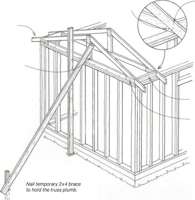
Installing the gable-end truss

Two 16d toenails into top plate


Two 16d nails into frieze block


Gable-end truss


Joist chord


Frieze block


Metal gusset


Installing the gable-end truss

the pile, and with the ridge point behind them, walk along the plates to the other end of the house frame. There, they flip the truss over with the ridge pointed out lying flat across the walls. Subsequent trusses lie on top of the first about every 2 ft like fallen dominoes.

Before raising the first truss upright, nail a 2x on edge against the outside wall frame near the center of the building. The gable-end truss will be nailed to this 2x, which will help hold the truss plumb (see the drawing above). At this point, you can raise a gable-end truss upright
and move it out flush with the outside of the end wall. Make sure you have the proper roof overhang on each side of the building and toenail the truss down through the joist chord into the double top plate with 16d nails spaced 16 in. o. c. Drive a temporary nail through the rafter chord into the upright 2x brace to hold the truss plumb. Brace this truss with a long 2x reaching to the floor or to a good stake driven in the ground.

Now come the frieze blocks, which are the blocks between rafters. When a house is to be covered with stucco,

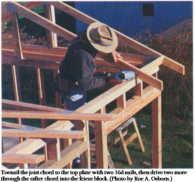
Подпись: Toenail the joist chord to the top plate with two 16d nails, then drive two more through the rafter chord into the frieze block. (Photo by Roe A. Osborn.)

blocks are often nailed vertically, directly on the top plate, flush with the outside. When the wall is covered with siding, blocks can be nailed just outside the wall and square with the truss, with the back side of the block touching the wall.

Frieze blocks serve as stops for the siding, eliminating the need to cut the siding around the rafters. If the rafter tails are to have a soffit (enclosed eaves and overhangs), nail the blocks directly over the walls. Remember, about every third block often contains a vent.

Nail the first frieze blocks into the gable truss at both outside walls with two 16d nails through the truss and into the block. Bring the next truss into position and set it with the rafter tails hanging over the same amount as the first.

It’s important that every truss overhangs the same amount so the rafter tails and ridge will be straight. Some carpenters go to great lengths—pulling lines, checking each rafter with a spacer—to ensure absolute straightness. I think it’s easier to set each truss close to right. When the entire roof structure is in place, snap a chalkline across the rafter tails and cut them to exact length. Now the fascia, which covers the ends of rafters and can be seen by the entire world, will be straight.

Toenail each truss to the top plate through the joist chord with two 16d nails on one side and one 16d nail on the other side. Then nail it to the frieze block (see the photo above). Once you set the second truss, measure to see if the block length is correct to give you

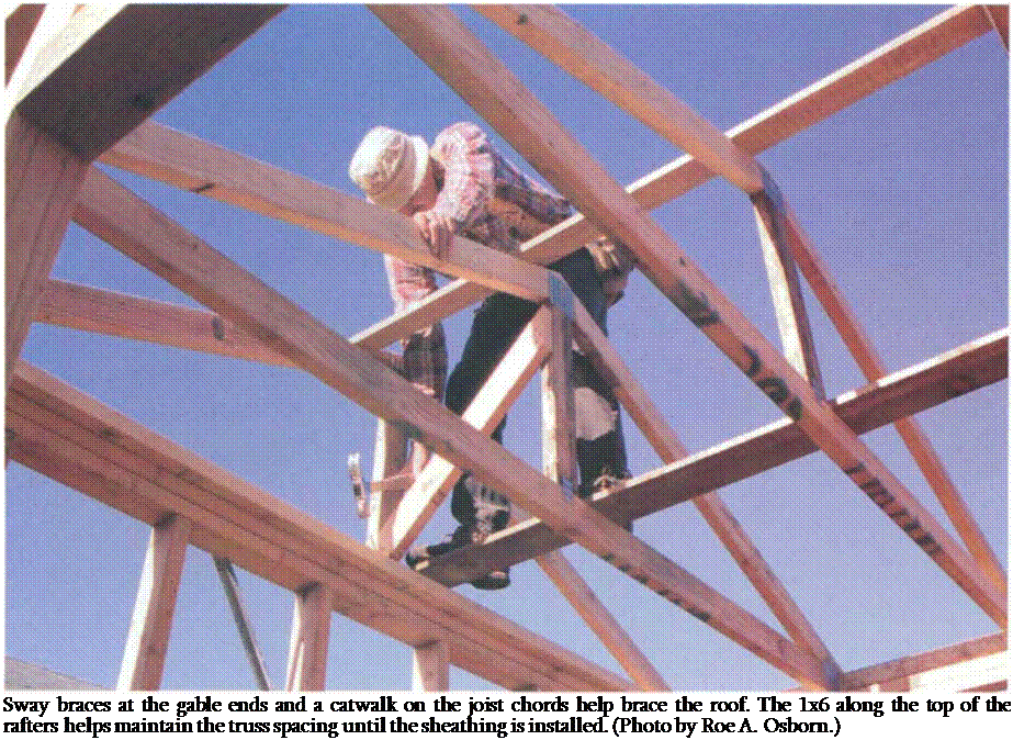
Подпись: Sway braces at the gable ends and a catwalk on the joist chords help brace the roof. The 1x6 along the top of the rafters helps maintain the truss spacing until the sheathing is installed. (Photo by Roe A. Osborn.)
24-in.-o. c. spacing. Keep checking this as you set subsequent trusses. When you reach the other end of the building, make sure the second gable-end truss is nailed flush with the outside wall just like the first.

CHOOSING CAULKS AND SEALANTS

If you walk down the caulk and sealant aisle at any well-stocked hardware store or home center, it’s easy to feel overwhelmed by the variety of products available. For quite a few years now, the terms “caulk" and “sealant" have been used interchangeably. In techni­cal terms, sealants are supposed to be more flexible than caulks, meaning that they are able to expand and contract with the move­ment of materials. But even caulk and sealant manufacturers have different definitions for these materials. For this reason, it’s smart to ask local builders and knowledgeable building-material suppliers which caulks and sealants are recommended for various jobs.

Although manufacturers haven’t cleared up the distinction be­tween caulks and sealants, they have improved their labeling with regard to specific applications. For example, “painter’s caulk" is an inexpensive latex-type caulk that is primarily used to fill gaps in and around interior trim prior to painting. Caulk that is labeled “for kitchen and bathroom use" is waterproof and will adhere to tile, porcelain sinks, acrylic shower units, and other surfaces found in those rooms. Silicone and urethane sealants are usually more expensive than acrylic or latex-acrylic caulks and are primarily used in exterior applications where extra durability, flexibility, and weather resistance are important. But be aware that acrylic paint does not adhere to some silicone caulks. Check with your supplier to see if your paint and caulk are compatible.

CHOOSING CAULKS AND SEALANTSПодпись: FIBERGLASS AND CELLULOSE INSULATION The two most common types of insulation used in homes today are fiberglass and cellulose. Both are partially manufactured from recycled materials. Fiberglass is made from 25-percent recycled bottles and other types of glass that are heated and spun into fibers. Cellulose insulation is made from 75-percent recycled newsprint, which is treated with fire retardant. Fiberglass comes in batts that are made in different widths and thicknesses. For shipping and storage, the batts are rolled up like long, thick blankets or packaged together in wall-length batts. Loose-fill fiberglass insulation is also available, but batts are much more common. Cellulose is usually blown into attic spaces and wall cavities (see the photo above). Blowers can often be rented at sup-ply stores, but usually an insulation contractor is hired to install cellulose. Cellulose is somewhat more expensive than fiberglass but has a higher R-value per inch, so it can end up saving you more money in energy costs. Like roof-shingle coverage, insulation coverage is calculated by the square foot. Add up the total square footage of the floor, the ceiling, and all the exterior walls. Unless you have an entire wall of doors and windows, don't subtract the wall openings.You may end up with a little extra insulation, but you can always put it in the attic. If you're buying insulation at a home center or an equivalent store, you'll find the per-roll coverage on the label. If you're buying it from a professional supplier, you simply need to provide the total square footage and whether the stud (and joist) bays are 16 in. o.c. or 24 in. o.c.That's because fiberglass batts are either 15 in. or 23 in. wide and are sized to fit between studs and joists at conventional spacings. Long, uncut rolls work well between floor and ceiling joists. Precut sections are also available for standard 8-ft.-high walls and save on installation time.

Caulks and sealants can be useful on small openings

For filling small gaps (up to lA in. or so), caulks and sealants sometimes work as well as, or better than, foam. A good sealant has suffi­cient flexibility to maintain a seal even though the joint expands and contracts slightly. For advice on selecting caulks and sealants, see the sidebar on p. 199.

If you plan to use caulk or sealant to fill a gap wider than /4 in., it’s a good idea to insert a backer rod into the joint before you apply the sealant. Available where caulks and sealants are sold, backer rod is made from dense, compress­ible foam. When wedged into a joint, it helps seal the area and lets you apply a thinner bead of caulk or sealant.

XS-HOUSE

With a couch, a stainless steel desk, sink and fireplace, a wet bath, two closets and lots of shelv­ing, plus a sleeping loft above, this portable structure was designed to house one full-time resident comfortably. A small refrigerator below the counter and a hot-plate are also included. If you were to count the loft, this house would actually be about 130 square feet.

1. Great Room 2. Kitchen 3. Wet Bath 4. Loft.

Square feet: 89

House width: 8’

House length: 15’

Road Height: 13’-5” Dry Weight: 4700 lbs

Porch: 3’x 7%’

Great Room: 6’ x 6%’ Kitchen: 4’ x 4[1]/2’

Bathroom: 4’x2’

Ceiling height: 6’ 6”

Loft height: 3’ 8”

-sizes are approximate

. Standard Cabinet Dimensions

Letter refers to "Figuring Dimensions" at left.

. Standard Cabinet Dimensions

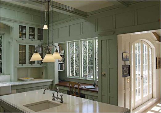
The arched valance over the farmhouse sink picks up curves in other rooms, including the double doors to the dining room, at right. In between, is a quiet alcove with enough room for cookbooks, a chair, and a computer.


image623

Recommended Counter Space and Clearances


Minimum Kitchen Work-Space Clearances


SPACE DIMENSION (in.

In front of base cabinet

36

Between base cabinet and facing wall

40

Between facing appliances

48

Work space plus foot traffic

60


image624

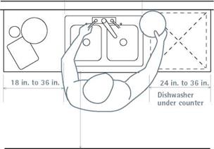
Подпись: Each work area-food prep, cooking, and cleanup-should have adequate counter space so a cook can work efficiently, with enough clearance to move safely. Counters with dishwashers underneath must be at least 24 in. wide; otherwise, 18 in. is the minimum. See “Minimum Kitchen Work-Space Clearances," at right.image625

a slight bend to your elbow. If the standard counter height of 36 in. above the finish floor isn’t right for you, lowering or raising it an inch or two may do the trick. However, if you’re think­ing of selling the house fairly soon, your ideal counter or shelf height may not appeal to the average buyer.

Equally important are the clearances needed to move easily in a kitchen—clearances that homeowners frequently overlook when laying out new kitchens. Be sure to allow enough room to open cabinet doors fully and still walk around them. Traffic lanes through work areas are vital because cooks frequently handle hot, sharp, or heavy objects: thus keep a 60-in. minimal clear­ance if the work area doubles as a corridor. Ideally, though, family traffic should bypass the cooking space. So if a kitchen has two or more doors, you may be able to reroute that unwanted traffic by eliminating one of those doorways, while gaining counter and cabinet space in the process.

COUNTER AND CABINET SPACE

Meal preparation consists of food prep, cooking, and cleanup, ideally with counter space for each job. Prepping the food—washing, cutting, and mixing—takes the most time, so give as much space as possible to counters near the sink and the cooktop.

Sink counters should be 24 in. wide on each side of the sink, though 36 in. is better, allowing plenty of room for food prep and the air-drying of pots and pans. Because dishwashers are 24 in. wide, they fit neatly under a 24-in. counter. If the kitchen is tiny and there’s no undercounter dish­washer, 18-in.-wide sink counters are minimal. Have a splashback behind the sink.

Cooktop counters should be at least 18 in. to 24 in. wide on both sides of the unit, and at least one side should be made of a heat-resistant mate­rial. Placing a stove on an exterior wall keeps exhaust-fan ducts short, but never place a gas stove in front of a window because a draft could blow out burners. The wall behind a stove should be washable.

By the refrigerator, next to the latch side, have a counter at least 15 in. wide so you can place things there as they go in and out of the fridge. If the refrigerator and the sink share a counter, the space should be 36 in. to 42 in. long. Because this counter is typically a food-prep area, you’ll need a large surface to store countertop appliances.

Cabinet space has few rules. The best indicator of how much cabinet space you need is the num­ber of appliances, bowls, and paraphernalia you own. Or use this rule of thumb: Figure 18 sq. ft. of basic storage plus 6 sq. ft. for each person in the household.

OUTLETS

Kitchen counters 12 in. wide or wider must have at least one electrical receptacle to serve them. All points on a counter must be within 2 ft. from a receptacle, and all counter receptacles must have ground fault circuit interrupter (GFCI) protection. Chapter 11 addresses this.

LAYOUT CHOICES: WORK AREAS

The person preparing and cooking the meal moves primarily in a space bounded by the refrigerator, the stove, and the sink—the so-called work triangle. When laying out such work areas, designers try to keep the distance traveled between the three points within 12 ft. to 22 ft. Three of the layouts shown below feature a work triangle. The fourth is a single-line kitchen, but the distance traveled should be roughly the same.

U-shaped kitchens are the most practical because they isolate the work area from family traffic. Because the cook spends most of the time

Face the Sun, and Shade the Glass

The first step to passively cooling your home is to stop the heat before it ever comes in. This is where siting and shading come into play. When designing a new house, you have a great opportunity to take advantage of orientation, but it’s also important (and often ignored) when adding to or altering an existing house.

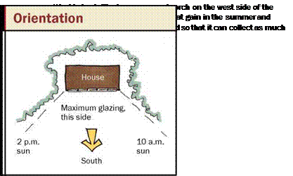
Here in the Northern Hemisphere, a house that faces south is optimal because that is where the sun comes from. Southern orientation makes it easier to control the amount of sunlight that enters the house. Even in the South, designing a house with a long east-west axis (minimal exposure to the east and west, maximum exposure on the north and south) allows you to take the best advantage of the sun. This strategy is associated with passive heating, but passive cooling also benefits from the same type of siting.

When the house faces south, simple over­hangs can shade it for the hottest part of the day, generally from 10 a. m. to 2 p. m. The

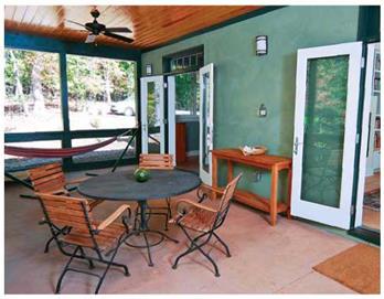
Подпись: solar gain in the winter as possible. This porch runs along the entire west side of the house, adding living space and providing cross breezes to the living room and master bedroom through two French doors.

Face the Sun, and Shade the Glass

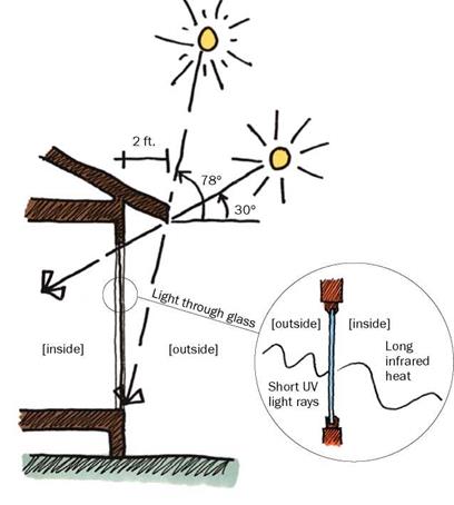
overhangs need to be sized correctly so that they not only block the sun at its hottest, but also allow light and warmth inside when the sun’s angle changes in the winter, and in the mornings and evenings. Because this fac­tor is based on the latitude where you live, the proper size of the overhang varies from region to region. The latitude where I live in North Carolina is 35 degrees north. That means the sun rises to 78 degrees above the horizon in summer and 30 degrees in winter. Here, a 2-ft. overhang is optimal because it blocks the hottest summer sun but lets the low winter sun shine inside (see the drawing on the facing page). To determine the opti­mal overhang where you live, see the chart on p. 131.

In the early morning and at sunset, when the summer sun is much lower in the sky, it’s harder to keep heat out of the house, even with overhangs. You can minimize this morning and evening heat gain by minimiz­ing the number of windows on the east and west sides of the house.

Another strategy is to locate shading de­vices, such as a screened porch, on the east
or west sides of the house to provide protec­tion from the low sun. By keeping the porch away from the south side, you’re not com­promising the daylighting and heat benefits available from the south. Other options for shading include pergolas, screens, and plant­ings. Pergolas, in particular, are a great op­tion; they not only shade the house but also create an outdoor space to enjoy. Growing vines on pergolas can increase the structure’s shading ability. Be sure to select deciduous varieties; they’ll provide maximum shade when fully leafed out in summer, but won’t block sunlight in winter.

Landscaping complements your house visually and also can help to keep it cool. Plant larger plants and trees to the east and west for shade. Plants absorb heat, lowering the temperature of air moving over them, so air that enters your house after traveling over the garden is actually cooler than the surrounding air. Low bushes and plantings also help by minimizing hard surfaces that absorb heat and radiate it back toward the house. These "heat islands"—driveways, walkways, and patios—work against any passive-cooling measures you might have taken, particularly if your house has win­dows that are low to the ground and capture the hot air that radiates off these surfaces. Lower roofs on porches or bump-outs, espe­cially those covered with asphalt shingles, radiate heat that can enter the house

Подпись: Based on the sun angle where I live in North Carolina, a 2-ft. overhang is optimal.Подпись: Summer sunПодпись: Winter sunFace the Sun, and Shade the Glassthrough windows open above them. In these situations, casement windows are the most effective at guiding cool breezes into the house, and they allow less of the heat radiat­ing off the roof to gain access inside. Avoid awning windows, which channel rising hot air into the house.

Enhancing passive cooling through orien­tation and siting is easiest when designing a new home. But installation of window over­hangs and the use of plantings and attached structures can boost the cooling power of existing homes as well.

BLINDS DON’T REALLY HELP

People often use internal shading, such as blinds, to keep the heat out of their homes. While it’s certainly better than letting sun­light stream in unimpeded, it’s really not a good strategy if you look at the science. When sunlight shines through the glass in windows, its wavelength lengthens. These longer wavelengths cannot travel back out through the glass, so the heat gets trapped inside. (This is how greenhouses maintain their warm environments.)

When you put up blinds, you block light from getting into the room. However, the heat from the sun’s rays has already entered through the glass. Because heat always moves from hot to cold areas, the heated air trapped between the window glass and the blind moves into the cooler areas of the house. Blinds may help a bit, but it’s better to invest in exterior shading devices to stop the sun from ever entering the house rather than trying to control it once it’s there.

CODE REQUIREMENTS FOR INSULATION

Most locales have an energy code that defines how well insulated your house must be. Check with the building inspector in your community for this information. Rather than requiring so many inches of fiberglass or rigid foam, these codes define insulation requirements in terms of R-value, or resistance to heat flow. The higher the R-value, the greater the insulating value. For example, code may require that exterior walls be R-11 or R-19. As it turns out, a 2×4 wall with fiberglass insulation designed for a 31/2-in. wall has an R-value of 11. Denser batts that increase the R-value to 15 for a 2×4 wall are available. A 2×6 wall with 5V2-in.-thick fi­berglass has an R-value of 19. Don’t try to stuff R-19 fiberglass batts into a 2×4 wall, though. Carpenters say that’s like trying to stuff a 1,000-lb. gorilla into a 500-lb. bag. It just doesn’t work.

Remember—code requirements set minimum standards. As far as building materials go, insulation is relatively inexpensive, so it’s often cost effective to install more insulation than what is required by code. A house with lots of insulation (in the attic, for example) will not only reduce your heating bill for years to come but may also save you money up front by reducing the size of the heating or cool­ing system you need to install!

to apply two beads of silicone sealant beneath their bottom plates. If this was not done for some reason, you can run a heavy bead of seal­ant where the inside edge of the bottom plate meets the subfloor.

Once the walls are framed, it’s important to install insulation in the sections that will be inaccessible after the wall sheathing is applied. As discussed in Chapter 4, these areas include the voids or spaces in the framing for corners, channels, and headers. Likewise, pay attention to areas where tubs and shower units will be in­stalled in exterior walls. You don’t want the stud cavities in these areas to be blocked off before you have a chance to insulate them.

Part of a sealing strategy may include house – wrap. Modern housewraps, such as Tyvek and Typar, are wrapped around the framed exterior

ф


walls and stapled over the exterior sheathing or (if exterior sheathing is not used) directly over studs and plates (see the photo on p. 197). Housewrap is effective at stopping cold air infiltration dur­ing winter months. And at all times of the year, it serves as a drainage plane behind the exterior siding, directing water that gets behind the siding downward, instead of into the wall cavity (see Chapter 6 for details on installing housewrap).

When installing windows and doors, first you need to apply a generous bead of sealant on the flange or the back of the exterior trim. Do this just prior to installation, as explained in Chapter 6. Make sure that kitchen soffits and dropped ceilings (especially those with heating or cooling ducts inside) are completely sealed off from wall and attic spaces. Use drywall or OSB, and do it now, if you haven’t already. These steps help prevent moisture-laden indoor air from moving into wall or attic areas, where it can condense and create major moisture problems.

Spray-foam insulation can handle a multitude of sealing tasks

Packaged in a pressurized can, foam insula­tion is extremely useful when it comes to filling gaps; sealing openings; and insulating narrow, confined spaces where fiberglass insulation doesn’t easily fit (see the photo at left).

Although it’s not cheap, spray-foam insu­lation is so helpful that I don’t build a house without it. It’s available in expanding and nonexpanding versions. I prefer the expanding type, because it does a better job of spreading out to fill voids. If you apply too much and the foam starts to expand beyond the intended area, don’t worry. Come back later, after the foam has hardened, and trim off the excess with a utility knife. Don’t try to wipe off excess foam when the material is still sticky; you’ll just create a mess. Here are some of the areas in the house where spray foam can be used:

IN HOLES IN BOTTOM PLATES. Use foam to fill the spaces around plumbing pipes, electrical or cable wires, and ducts that


CARBON MONOXIDE MONITORS SAVE LIVES

Although tight houses improve energy efficiency, they also increase the danger of carbon monoxide (CO) poisoning. CO is a byproduct of combustion from numerous sources. Woodstoves, oil furnaces, gas-fired stoves, water heaters, and fireplaces can produce hazard­ous levels of CO. The problem with CO is that you can’t see it, taste it, or smell it—and it’s poisonous. For this reason, CO detectors should be installed in any home that uses a fuel-burning appliance. Detectors are relatively inexpensive; you can buy plug-in units or modules that are permanently wired into the electrical system. Install them in kitchens, utility rooms, and wherever a CO-producing appliance is located. CO detectors should be placed at least 5 ft. from the floor or on the ceiling.


Spray foam is sticky stuff.

When applying spray-foam insulation, wear plastic gloves so the foam doesn’t get on your hands. The foam is sticky and can stain your skin.


CODE REQUIREMENTS FOR INSULATION

Expanding foam is excellent for sealing and insu­lating small spaces. A little foam goes a long way, so it’s best not to apply too much at one time.


ф


198 COMFORT INSIDE


Ф


CH08_HAUN_pgs.194-211.indd 198


2/3/11 12:13 PM


when it is compressed. It’s better to insulate narrow spaces with foam insulation. The spaces between the window or door jamb and the rough opening can also be “foamed,” but be careful not to apply too much expanding foam in those areas. Because jambs are usually only 3/4 in. thick, the foam’s expansive action can cause them to bow inward.

AROUND PLUMBING AND ELECTRICAL LINES THAT PASS THROUGH EXTERIOR WALLS. If your house has exterior faucets, seal the hole around each one with foam insulation. Holes for outdoor electrical lines and outlet boxes in exterior walls should also be sealed.

DESIGN OF MULTIPLE-MOUNT SIGN SUPPORTS

Multiple-mount sign-support assemblies (Fig. 7.22) are required whenever the surface area or width of the sign is too large to withstand the wind and ice loads. Each state has guidelines, in the form of tables and graphs, that are used to select the size and numbers of supports required to withstand the prevalent environmental loads in different parts of the state. These guidelines should be used to determine the required size and number of supports. The design of multiple-sign-support assemblies requires considerations that

FIGURE 7.22 Multiple-mount sign support.

in some instances differ from single-sign-support assemblies. These considerations

include the following:

• Tests have demonstrated that vehicles leaving the roadway at an angle can strike more than one support if supports are spaced closer than 7 ft (2100 mm). If two supports are spaced less than 7 ft (2100 mm) apart, they must pass a crash test as a dual support assembly. Installing two acceptable single sign supports does not guar­antee acceptable multiple-support performance.

• For multiple supports, the sign panel itself is an important part of the sign structure during impact. Depending upon the design, the sign panel must carry the weight of the impacted support and/or provide sufficient rigidity to enable the hinge mechanisms to activate. The sign panel must be made of material of sufficient thickness that it does not break into pieces when a support is impacted.

• Acceptable performance in multiple-support systems requires the sign panel to remain attached to the support(s) that are not impacted. This intended performance can be destroyed by:

The use of bolts to fasten the sign panel that are too small

The absence of washers, which allows the bolt head to pull through the sign panel Sign panel bracing that will twist or break and therefore not transfer the sign weight to the undamaged support(s)

• Slip base mechanisms must be designed with the proper sized bolts and washers. Bolts that are too small may not withstand the wind load forces. Oversized bolts can result in binding or friction forces between the base plates. Washers that are too small can deform into the slots and bind the plates together.

• Large multiple-support signs have a hinge mechanism that allows the support to swing upward upon impact. The hinge height should be at least 7 ft (2100 mm) above

• Hinged multiple sign supports are generally designed to operate safely when impacted from one direction (they are unidirectional). They can be made bidirec­tional by selecting the proper hinge arrangement.

• Two posts within a 7-ft (2100-mm) path should each have a mass that does not exceed 18 lb/ft (27 kg/m).

• Supplemental signs or horizontal members between the supports and below the hinge should not be used.

• Multiple-support systems that are designed with anchor bases should have a maximum of 4 in (100 mm) from the ground to the highest part of the anchor. This will prevent small vehicles from snagging the undercarriage on the anchor.

• Selection of unidirectional, bidirectional, or multidirectional support assemblies should be based on the possible directions from which the signs can be impacted. Unidirectional assemblies will not function correctly unless impacted from the front along the longitudinal axis of the slotted bolt holes. Bidirectional assemblies will function properly when struck from the front or the back. Impacts can be expected to occur from both travel directions in all cases except roadside sign supports located on the right side of divided roadways that have wide medians or positive median barriers. Bidirectional or multidirectional support assemblies should be considered for: Signs placed in the median that are within the clear recovery area of the opposite direction of travel

Signs placed on two-lane roadways or undivided multilane roadways

Signs placed near ramp terminals or intersections where impact could occur from

any approach.

The majority of support types approved for use as single sign supports are approved for multiple installation. The approved usage as multiple supports, however, often requires the use of breakaway designs and a limit on the number of supports allowed within a 7-ft (2100-mm) distance of each other. Dual and triple installation refers to installing two and three supports, respectively, within a 7-ft (2100-mm) radius distance of each other. Acceptance of multiple-sign-support systems is based on the same vehicle deceleration characteristics used for single sign supports except that all of the supports within the 7-ft (2100-mm) path are impacted. Selection of approved multiple sign supports, therefore, requires knowledge of the number of supports required and the associated systems approved for use by FHWA.

Multiple-sign-support assemblies are required for signs with large surface areas but also for wide signs. For example, a guide sign 5 ft X 2 ft (1525 mm X 610 mm) has a small sign area but will need more than one support to prevent the sign assembly from being damaged due to environmental loads. Sign panels that have relatively small surface areas but require multiple supports because of their shape can generally use two smaller- size supports than would be required if they were installed with a single support.

Build Quality, Gravity and Inertia

Note that in all of the joining methods described above, the beams are not diminished in cross-section, so full shear and bending strength is maintained.

1 cannot over-emphasize the importance of maintaining a good standard of “build quality.” One member should bear flat on another, without wobbling. The end of a beam should bear at least four inches on the supporting post or beam below, if possible. Timbers should be vertically plumb and horizontally level. The design should assure that the line of thrust is always transferred directly in compression from one member to another.

By paying attention to the build quality, you enlist a great ally, which is the force of gravity. Gravity is very precise: it always works exactly vertically (which enables a bubble-level to function properly, by the way). And it is reliable; that is to say, it is working for you every morning when you wake up, and through the night as well.

Gravity and its close relative inertia are very important parts of all heavy timber-framed structures. Earth-roofed structures help even more in this regard. Our roof at Earthwood weighs between 6о and 120 tons, depending on moisture and snow loads. Even at the low end (dry, no snow), the 6o-ton load has a tremendous inertia. The seven load-bearing eight-by-eight posts downstairs are not even pinned to the floor; with at least three tons on each post, they aren’t going anywhere. (I know, three times seven tons is only 21 tons. The external walls and central masonry column support the rest.) Now, I don’t advise not pinning the posts to the floor — “Do as I say, not as I do!” — but I just thought you might find our experience interesting.

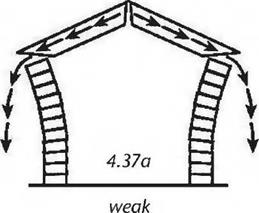
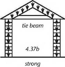
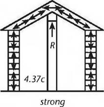
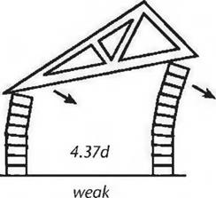
Gravity can work against you, too. You have probably seen lots of diagrams like Fig. 4.37. These drawings depict freestanding cordwood walls, which are strong on compression and weak on tension. Using cordwood exaggerates the effect of the stresses a bit, but helps make the point. The same sorts of compression and tension forces are at play in a post-and-beam wall. They may be less obvious, but they need to be attended to for the same reasons.

In Fig. 4.37a, the roof load wants to follow gravity’s path, but the angle of the rigid rafters transfers the downward thrust to an outward thrust on the walls, and the building falls down. This would be an excellent example of egregiously bad build quality. In Fig. 4.37b, the tie beam has a tensile strength sufficient to offset

image76image77image78image79the outward thrust. Another way of thinking about it is that the tie beam turns the roof structure into a giant rigid triangle, a triangle with — and this is important — a flat bottom. Gravity’s downward thrust is carried straight down onto the vertical walls. This is how trusses work.

In Fig. 4.37c, rafters are well-tied to a ridge beam, which, in turn, is supported by posts. If the tops of the rafters can’t go down — and they can’t because of the reactionary load “R” provided by the posts — then they cannot put an outward thrust on the walls.

The importance of level and plumb is illustrated in Fig. 4.3yd. Here, we have a nice rigid triangular truss, but the bottom chord of the truss, which is inclined, alters the vertical line of thrust. This resultant vector of force places unacceptable stresses on the walls, as shown. Working with gravity, and not against it, is always a good idea. In this example, if the walls were the same height, and the bottom chord was horizontal, the line of thrust would be straight down onto the walls, which — being strong on compression — would then provide the required reactionary load.

Build quality, gravity, and inertia can be important allies… or deadly enemies.

Frangible Couplings

Acceptable single-sign-support performance can be achieved with the use of frangible couplings and load concentration couplers (Fig. 7.21). These couplings are either fabricated from die cast aluminum or extruded from an alloy. The couplers are used as inserts that bolt the support post plate to the anchor piece plate. They present a weak point on the sign-support assembly that fractures upon impact. The majority of applications for frangible couplings are for multiple sign supports. These couplings are discussed more fully in Arts. 7.5.2 and 7.8.2.

7.4.1 Considerations in Design of Slip Bases

Failure of slip base designs to release properly can be due to the bolt torque, the gauge or thickness of the keeper plates, or the weight of the support. The following should be adhered to in the design of slip base supports:

• Horizontal and inclined slip bases can be constructed with wide-flange, standard – shape, and round signposts. Multidirectional designs are usually constructed with round signposts to enable the multidirectional rising action of the lift cone.

TABLE 7.7 Round Sign-Support Sizes for Slip Base Designs Based on Sign Area

a. Size and area in

U. S. Customary units

Round post internal

Total sign

diameter, in

area, ft2

2.0

0 to 4.0

2.5

4.0 to 8.0

3.5

8.0 to 20.0

4.0

20.0 to 36.0

b. Size and

area in SI units

Round post internal

Total size

diameter, mm

area, m2

51

0 to 0.37

64

0.37 to 0.74

89

0.74 to 1.9

100

1.9 to 3.3

• The post should not weigh more than 45 lb/ft (67 kg/m), and the total weight of the support post, hardware, and sign panel should not be more than 600 lb (270 kg).

• The bolts clamping the top and bottom portions of the slip base together should not be tightened more than the specifications. Overtorquing creates high friction between the slip base elements and may prevent the post from releasing properly. The clamping force must be controlled by installing the bolts with a torque wrench, using torque-limiting nuts, or using designs that are not dependent upon specific torque requirements.

• Washers used with the clamping bolts must be of sufficient strength to prevent the washers from deforming into the plate slots when the bolts are tightened to specification.

• The stub height must be no more than 4 in (100 mm) above ground level at the highest point of the slip plate assembly.

• No bolts from the anchor piece should project into the upper support assembly.

• The choice of the proper sign-support type for slip base designs is dependent upon the wind load, sign panel size, and the criterion that the weight of the sign support and sign not exceed 600 lb (270 kg). As a general rule, the maximum sign area presented in Table 7.7 can be used in selecting the appropriate size of wind sign support. Determining the maximum sign size for areas with high wind loads, or for the selection of post sizes other than round shapes, should be performed with reference to state requirements.