OTHER CONSIDERATIONS
In addition to the choices about pitch, shape, and structure discussed above, many other decisions contribute to the overall performance of the roof. These include selection of sheathing, underlayment, and roofing material; eave, rake, and flashing details; gutters and downspouts; and insulation and ventilation of the roof assembly. All of these issues are discussed in this chapter.
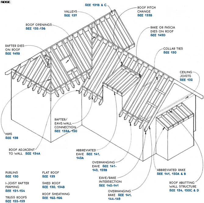
Rafter sizes are usually 2×6, 2×8, 2×10 or 2×12, and spacing is usually 16 in. or 24 in. o. c. Species of wood vary from region to region. Rafter sizing depends primarily on span, spacing, roof loads, and sometimes on required insulation depth.
For a rafter-span table, see 131A.
![]()

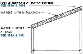
Stick-framed rafters may be supported by the walls of the building, by a structural ridge beam, or by purlins.
Simple-span roof – The simplest sloped roof—the shed roof—has rafters that span from one wall to another, as shown at right. These rafters must be strong enough to cany the dead-load weight of the roof itself and subsequent layers of reroofing, plus the live-load weight of snow. The rafters must usually be deep enough to contain adequate insulation.
The total roof load is transferred to the ends of the rafters, where it is supported by the walls. In the simple example at right, each wall carries part of the roof load.
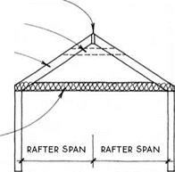
Triangulated roof – Common (full-length) rafters are paired and usually joined to a ridge board, as shown in the drawing at right. Each rafter spans only half the distance between the two walls (the gable roof, shown in the drawing at right, is the simplest version). Horizontal ties—either ceiling joists or collar ties— form a triangle with the rafters. Ceiling joists are generally located on the top plate of the walls but may also be located higher to form a partially vaulted ceiling. Collar ties are usually nailed near the top of the roof between opposing rafters and spaced at 4 ft. o. c. Collar ties are not sufficient by themselves to resist the outward thrust of the rafters.
Rafters in triangulated roofs are shallower than those in shed roofs of equal width because they span only half the distance of the shed rafters and because they do not usually contain insulation.
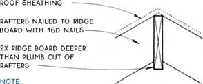
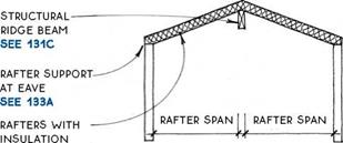
Structural ridge beam—The horizontal ties that are required in a triangulated roof may be avoided if the rafters are attached at the ridge to a structural ridge beam (or a wall), which effectively changes the triangulated roof into two simple-span roofs, as shown in the drawing below.
|
|
NONSTRUCTURAL RiDGE BOARD SEE 133B COLLAR TiE
RAFTER
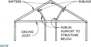
Purlin—A purlin is a horizontal member that supports several rafters—usually at midspan. Purlins were commonly used to help support the long slender rafters of pioneer houses and barns. Today they are also used occasionally to reduce the span of a set of rafters, but the purlins must themselves be supported by the frame of the structure, as shown in the drawing below.
|
the NAME "PURLiN" iS ALSO GiVEN TO A Member That SPANS across RAFTERS TO SUPPORT ROOF DECKiNG. SEE 150C |
![]() ALLOWABLE RAFTER SPANS IN FEET
ALLOWABLE RAFTER SPANS IN FEET
|
Rafter size, |
Joist spacing (ft.) |
||
|
species, and grade |
12 in. o. c |
16 in. o. c. |
24 in. o. c. |
|
2×6 spruce-pine-fir #2 |
12.1 |
11.0 |
9.0 |
|
2×6 Douglas fir #2 |
12.6 |
11.3 |
9.2 |
|
2×8 spruce-pine-fir #2 |
15.9 |
14.1 |
11.5 |
|
2×8 Douglas fir #2 |
16.5 |
14.3 |
11.6 |
|
2×10 spruce-pine-fir #2 |
19.9 |
17.2 |
14.0 |
|
2×10 Douglas fir #2 |
20.1 |
17.4 |
14.2 |
|
9.5 x 2.06-inch I-joist |
21.4 |
19.4 |
16.8 |
|
2×12 spruce-pine-fir #2 |
23.0 |
19.9 |
16.3 |
|
2×12 Douglas fir #2 |
23.4 |
20.2 |
16.5 |
|
11.9 x 2.06-inch I-joist |
25.5 |
23.1 |
19.0 |
This table compares two species of sawn lumber and one I-joist for use as rafters on a roof with a 30-psf live load. The table is for estimating purposes only. For a roof-sheathing span table, see 163.
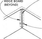
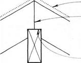
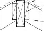
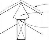
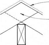
RIP RiDGE BOARD iF
iNTERiOR finish meets Common Rafters
AT RIDGE.
slightly undercut the plumb CUT ON BARGE OR VERGE RAFTERS IF LuMBER IS GREEN; THE BoARDS will shrink to MEET at centerline.



 |
 |
 |
NAIL iNTo RiDGE BoARD NEAR BoTToM of RAFTERS; uPPER NAILS MAY BE ADDED AFTER lumber DRIES.
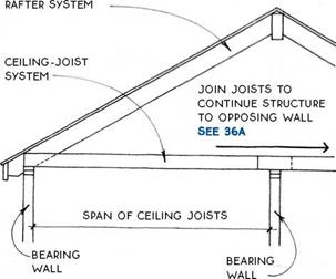
Ceiling joists are very similar to floor joists. In fact, the second-floor joists of a two-story building act as the ceiling joists for the story below. Ceiling joists are distinguished from floor joists only when there is no floor (except an attic floor) above the joists.
Ceiling joists are sized like floor joists. The span of the joists depends on spacing and whether the attic above the joists will be used for storage.
|
|
|
ALLOWABLE CEILING JOIST SPANS iN FEET
|
This table is based on a light attic load of 20 psf and a deflection of L/360. The table is for estimating purposes only.
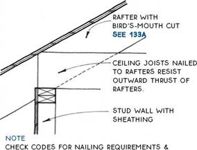
The joists can function as ties to resist the lateral forces of rafters. For this purpose, it is important to attach the joists securely to the rafters.
|
ANGLE NAiLS THROUGH JOiSTS iNTO RAFTERS TOWARD CENTER OF BUiLDiNG. |
The underside of ceiling joists is often furred down with a layer of 1x lumber to resist plaster or drywall cracking due to movement of the joists. The drawing below illustrates furring parallel to the joists to resist cracking along a beam that interrupts the continuity of the joists. Furring perpendicular to the joists, usually called strapping, is also common.
![]()

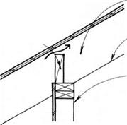

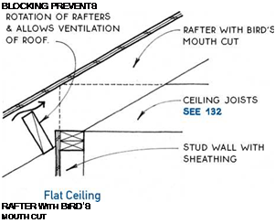
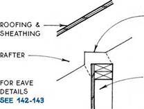
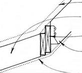 At walls or beams that support them at the eave, rafters are cut at the point of support with a notch called a bird’s mouth.
|
|
|
BiRD’S MOUTH CUT |
|
EAVE STUD WALL |
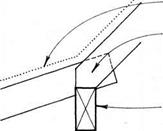
The width of the bird’s mouth is equal to the width of the sheathed stud wall (or unsheathed wall if sheathing is to be applied later). The underside of the rafters should meet the inside corner of the top of the wall. This is especially important if the ceiling is vaulted and a smooth transition between wall and ceiling is desired (see below).
BLOCKING pREVENTS
rotation of rafters & allows ventilation of roof.
note
for rafter support at rake WALL, SEE 1340.
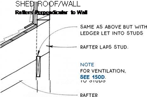
Wherever the pitch of a roof changes from shallow to steep (as in a gambrel roof) or from steep to shallow (as in a shed dormer) the two ends of the rafters must be supported. If the pitch change occurs over a wall, the wall itself will provide the support.
If the pitch change does not occur over a wall, the support will have to be provided by a purlin or a beam (header).
|
|
|
ROOFING & SHEATHING LOW-PITCH & HIGH-PITCH RAFTERS LAP/ BOTH BEAR ON SUPPORT. |
|
BEAM. PURLIN. OR WALL |
|
|
|
ROOFING & SHEATHING LOW-PITCH & HIGH-PITCH RAFTERS LAP.- BOTH BEAR ON SUPPORT. BEAM. PURLIN. OR WALL |
Pitch Changes with Support Below
DouBLE 2X HEADER
up-slope RAFTER on joist hanger
– – FINISH CEILING

Pitch Changes without Support Below
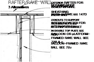
The end rafters of a gable or a shed roof are supported by the walls under them, called rake walls. The framing of the rake should be coordinated with the detailing of the rake. Of the three drawings below, the first example is the simplest method of support and is used with all types of rake, often in conjunction with an unfinished attic. The second example is best for supporting lookouts for an exposed or boxed-in rake. The third example provides nailing for a boxed-in rake or an exposed ceiling. Elements from the three examples may be combined differently for specific situations. For rake-wall framing, see 72A, B & C.
ROOFiNG ROOF SHEATHiNG
RAKE TRiM SEE 146-147
END Rafter Balloon OR
 |
 |
platform-framed rake wall SEE 72B
![]()
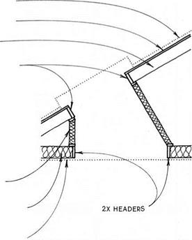
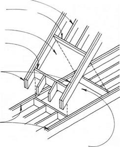
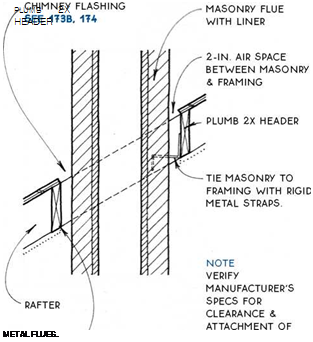
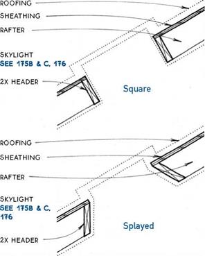
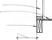 Framing the elements that project through the roof of a building—skylights, chimneys, and dormers— begins with a rectangular opening in the framing.
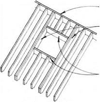
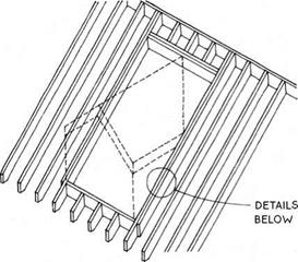
For openings in a single roof plane framed entirely with common rafters, framing is relatively easy. An opening three rafter spaces wide or less can be made by heading off the interrupted rafters and doubling the side rafters, as shown below. Obviously, it is more efficient if the width and placement of the opening correspond to the rafter spacing. Larger openings should be engineered. Openings that straddle hips, valleys, or pitch changes must have special support, special framing, and special flashing.
RiDGE
DOUBLED COMMON RAFTER AT SiDES OF OPENiNG
TOP & BOTTOM RAFTER HEADER (OFTEN DOUBLED)
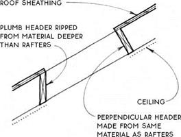
Headers for simple openings are, in most cases, either plumb or perpendicular to the rafters, as shown in the drawing below. Plumb openings require a header deeper than the rafters.
|
FOR dormer OpENiNGS SEE 135B. FOR skylight OpENiNGS SEE 136A & B. FOR chimney openings SEE 1360. |
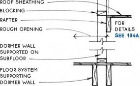
Dormers are often more than three rafter spaces wide so their structure cannot be calculated by rules of thumb. The opening in the roof may be structured to support all or part of the loads imposed by the dormer. The dormer walls and roof are framed like the walls
|
and roof of the main building.
|
If the dormer walls do not extend below ceiling level, the roof structure at the edge of the opening must support the dormer.
DORMER WALL SUPPORTED ON ROOF FRAMING
ROOF SHEATHING
ENGINEERED RAFTERS AT SIDE OF DORMER OPENiNG ■ ""
If the dormer has side wails that extend to the floor,
the floor may be used to support the dormer, and the rafters at the side of the opening may be single.
|
|

![]()
|
|
|
||
ROOFiNG SHEATHiNG RAFTER
![]()


![]()
 2X HEADERS
SKYLiGHT
SEE 175B & C, 176 iNSULATED
stud wall between roof rough opENiNG & OEiLiNG RouGH opENiNG
LiNE oF FiNiSH OEiLiNG
![]()
 |
|
 |
|
дЛ SKYLIGHT OPENING

![]()
![]()
![]()
![]()
![]()


![]()
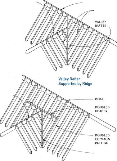
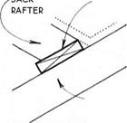
The inside corner of two intersecting roof planes is called a valley. In most cases, valleys are supported by a valley rafter that extends from the outside wall of the building to the ridge or to a header. These valley rafters support large loads and should be engineered. Jack rafters support the area between the valley rafter and the ridge or header.
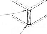
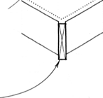
TOP EDGE OF JACK FAFTERS ALiGN WiTH CENTER OF VALLEY RAFTER.
bottom edge of valley rafter must be flush with bottom of jack rafters WHEN interior surface is to be finished
or
it may project below jacks when no interior finish is required, or if jack rafters are furred.
As shown at right, valley rafters can be supported at the top by a ridge or by a header. The ridge support system is more practical when the ridges of the intersecting roofs are close together; however, the header support system is better when the lower ridge intersects the main roof near or below the center of the rafter span.
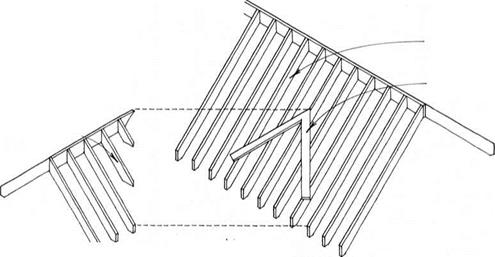
Where headroom is not required between intersecting roofs, a simpler “farmer’s valley” or “California valley” may be constructed. This valley is made without a valley rafter. One roof is first built entirely of common rafters without any special valley framing. Then 2x sleepers are installed over the rafters or over the sheathing of the first roof, and jack rafters are attached to the sleepers.
|
|
|
. ІАГІ^ |
|
2x sleeper |
|
common RAFTER |

|
|
|
|
|
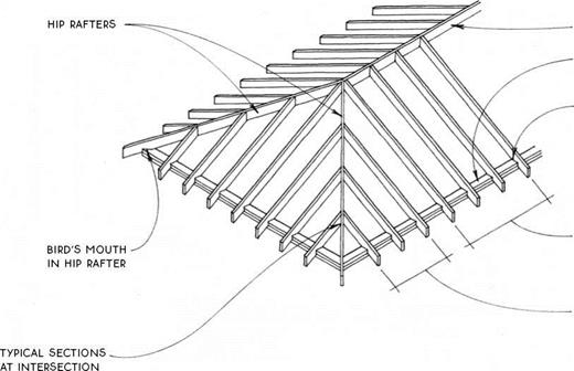
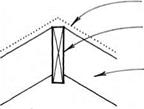
A hip is the outside comer where two planes of a roof meet. It is composed of a hip rafter at the comer and jack rafters from the hip to the eave. The hip rafter is supported at its lower end by the wall at plate level (or by a post) and at its upper end by the ridge (or by a wall).
Most codes require that the hip rafter project below the bottom edge of the jack rafters (see the top drawing at right). This is not veiy logical because, unlike a valley rafter, a hip rafter does not support much roof load.
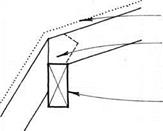
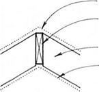
The extra depth presents no problem in an attic space, but if the inside face of the roof is to be made into a finish ceiling, the hip rafter will have to be ripped to allow the planes of the finish ceiling to meet (middle drawing at right). If codes will not permit ripping the hip rafter, furring may be added to the underside of the jack and common rafters to allow the finish ceiling to clear the hip rafter.
The top ends of the jack rafters may be cut off to permit venting at the top of the hip roof (bottom drawing at right).
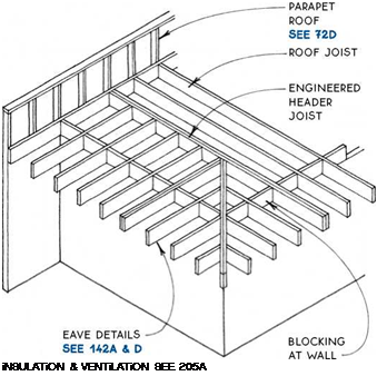

The framing of a flat roof is more like a floor than it is like a pitched roof. The joists are level or nearly level and support the ceiling below and the live loads above. Connections to walls are like those for floors (see 32), as are the framing details for openings (see 38B) and cantilevers (see 39A). As for floors, the structure of a flat roof may be a joist system (dimension lumber or I-joists), a girder system, or a truss system. Blocking and bridging (see 38A) must be considered at the appropriate locations.
Flat roofs are unlike floors, however, in that they are not really flat. They might be more properly called “low – slope” roofs because they must slope at least Vi in. per ft. in order to eliminate standing water. This minimal slope may be achieved in several ways:
1. The joists themselves may slope if the ceiling below does not have to be level, or if the ceiling is furred to level.
2. Trusses may be manufactured with a built-in slope.
3. Shims may be added to the top of the joists.
4. Tapered rigid insulation may be added to the top of the sheathing.
5. The joists may be oversize and tapered on top.
6. Sloped rafters can be scabbed alongside level ceiling joists.
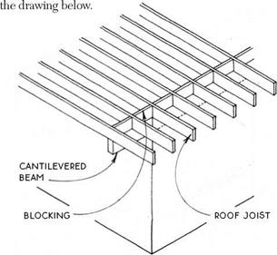
The easiest and most direct way to support an overhang at the corner of a flat roof is with a beam below the joists cantilevered from the top of a bearing wall, as shown in
|
|
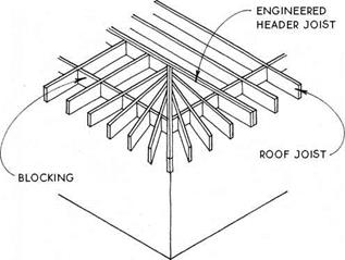
A traditional framing method for a cantilevered corner without a beam is with joists that radiate from a doubled central diagonal joist, as shown below. A strong fascia board is advisable here, as with all framing using cantilevered joists.
|
|
A third option for framing a cantilevered comer is shown below. All methods illustrated should be engineered by a professional.
NOTE
USE RAFTER-SPAN TABLE FOR FLAT-FOOR JOiST SPANS, SEE 131A.
Designing the basic shape of the roof and designing the configuration of eaves and rakes are the most critical tasks in roof design. Stylistically, the selection of eave and rake types should complement both the roof form and the roofing material.
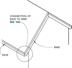

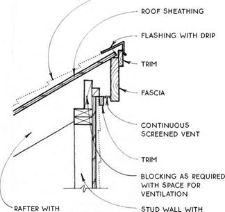
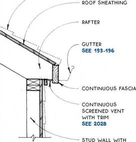
 Functionally, the eave and rake should help protect the building from the elements. The shape of the roof will suggest certain eave and/or rake shapes (see 140B), and certain eave types work best with particular rake types (see 141).
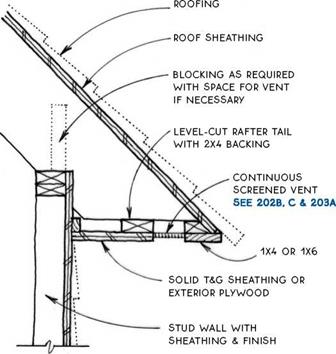
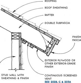
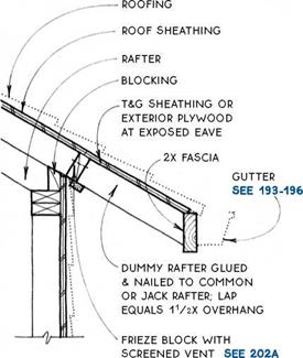
Eave— The eave is the level connection between the roof and the wall. Eaves are common to all sloped roofs and often to flat roofs. There are four basic types of eave (see 141). For eave details, see 142 and 143A & B.
Rake- The rake is the sloped connection between the roof and the wall. Only shed and gable roof types and their derivatives have a rake. There are three basic types of rake (see 141). For rake support and rake details, see 144-147. The way in which one edge of a
The basic shape and structure of a roof system need to be coordinated with the finish of the roof at the edges. The shape of the roof affects the treatment of the edges, and vice versa. A hip roof, for example, is easier to finish with a soffited eave than is a gable roof. The basic roof shapes are best suited for the following finish treatment at the edges:
|
|
|
|
|
|
|
|
|
|


^ ROOF SHAPE & EAVE/RAKE SELECTION
roof is finished affects the detailing of the other edges. For example, a soffited eave on a gable-roofed building is easier to build with an abbreviated rake than with an exposed rake. The designer should attempt to match the level edge of the roof (the eave) to the sloped edge (the rake).
In examining the details of the eave and rake, therefore, the two must be considered as a set. It is logical to
start with the eave, because all sloped roof types have eaves, but not all have rakes.
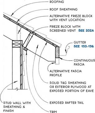
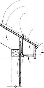
There are four basic sloped-roof eave types. All four types are appropriate for hip roofs, and all but the sof – fited type can make a simple and elegant transition from eave to rake on gable and shed roofs. The eave types and their most appropriate companion rakes are diagrammed below.
|
|
||||
|
|||||
|
|||||
|
|||||
|
|||||
|
|
||||
|
|||||
|
|||||
|
|
||||
|
|||||
|
|
|
|||
|
|||||
|
|||||
|
|||||
|
|
||||


|
|
|
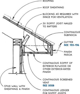
![]()

 |
NOTE
THiS DETAiL WORKS WELL ON STEEP ROOFS, WHERE A FASCiA MAY APPEAR TOO BULKY.
NOTE
no gutter shown. hang gutter from strap SEE 1950
OR USE VERTiCAL FASCiA ON PLUMB-CUT RAFTERS TO ACCOMMODATE STANDARD GUTTERS.
|
||
|
||
|
||
|
|
||
|
||
|
||
|
||
 |
||
|
||
|
|
||
|
|
![]()


![]()


![]()

![]()
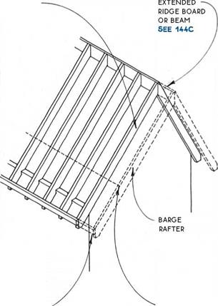
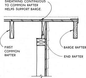
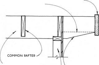
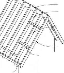
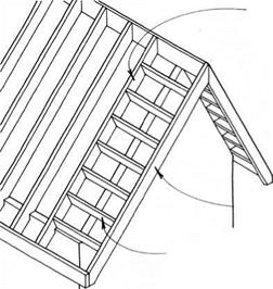
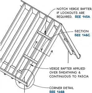
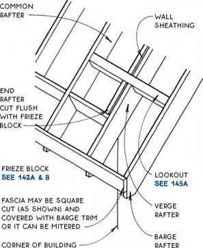
When an overhang is required at the rake, the overhang is made with barge rafters, which stand away from the building and need support. There are several ways to support barge rafters. The roof sheathing alone may be strong enough to support the barge rafters (see 144B), or the ridge board or beam can be designed to support the barge rafters at their upper ends (see 144C), and the fascia may be extended to support the barge rafters at their lower ends (see below). Lookouts or brackets may be also used to support an overhanging rake (see 145A & B).
NOTE
VERGE RAFTER NOT SHOWN; FOR Details SEE 146.
stud wall under end common rafter


![]()

![]()


![]()
![]()
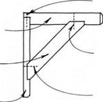 If the ridge, the fascia, and the sheathing together do not provide sufficient support for the barge, lookouts may be added. Lookouts extend from the barge rafter to the first common rafter (or truss) inside the wall. The lookouts are notched through the end rafter at the top of the wall or, alternatively, bear directly on the wall. The size and spacing of lookouts depend on rafter spacing and live loading.
FiRST
COMMON
RAFTER
END OR VERGE RAFTER
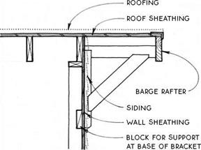
Brackets attached to the face of the wall framing can support the barge rafter by means of triangulation.
nails
Attaching the bracket to the inside of the barge rafter avoids problems of weathering.
|
|
![]()
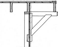
The alternative bracket connection to the barge rafter shown below is common on Craftsman-style buildings. With this detail, moisture collects on top of the bracket, and this contributes to the decay of the bracket and the barge rafter.
|
|
 |
NOTES
EXPOSED ROOF SHEATHiNG MUST BE EXTERiOR-RATED PANEL OR SOLiD (T&G) MATERiAL.
 FOR ALTERNATiVE DETAiL WiTH TRiM BOARD, SEE 147A & B.

![]()







Leave a reply