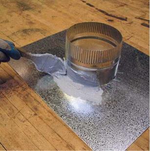
Soffit-to-Ridge Ventilation
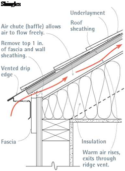
Подпись:Подпись: Drip-edge vents allow you to add ventilation to a roof that has no soffits. Carefully cut off the top 1 in. of the fascia, using a nail-cutting circular- saw blade (wearing eye protection). Slide the upper leg of the vent under the shingles and, if possible, under the underlayment.If sealing holes and insulating attic floors are the first steps in reducing excessive moisture and heat in an attic, increasing ventila­tion is the second. And nothing exhausts moisture or cools the area under a roof as effectively as passive soffit-to-ridge ventilation, as shown here and in Chapters 5 and 7. (Gable-end vents help but are usually 1 ft. to 2 ft. below the highest and hottest air; power vents require electricity to do a job that soffit-to-ridge vents do for free.)

As a bonus, in winter, cool incoming air can prevent snowmelt and ice dams along eaves. Also, in summer, when unvented roofs can reach 150°F to 160°F, soffit-to-ridge ventilation can prolong shingle life and make upper-floor rooms appreciably cooler.

Keeping vent channels open from soffit to ridge is essential to keeping air flowing. Continuous soffit vents are typically screened to keep critters from blocking the vents with nests or food caches. In snow country, experts recommend baffled ridge vents because they’re less likely to become clogged by wind-driven snow. (Wind passing over baffles creates a negative pressure that sucks air up from under the roof, clearing the vents.). And whenever there’s insulation between rafters or attic floor joists, install air chutes (also called baffles) to hold insulation back from vent channels.

If the roof has no overhang (and thus no soffits), you can still ventilate its lower edges. Trim back the top 1 in. of fascia boards, as shown at right, and install vented drip edges, which have perforated or slotted undersides. Their upper flanges fit under shingle starter courses. Add a ridge vent and you’re set to go.

Подпись: TIPПодпись: You can further reduce air infiltration by caulking around the interior edges of exterior frame walls. Caulk before installing a cold-climate vapor barrier or (in warm climates) before fastening drywall panels. In either climate, apply a flexible latex caulk to top and bottom plates, to the first studs of intervening walls, and around the rough openings of doors and windows.Подпись: llll

tears. Vapor barriers must never be installed on ceilings, because water vapor should be allowed to rise into and be ventilated out of the attic. And vapor barriers should generally not be installed in moderate or hot climates because buildings in those regions tend to dry toward the interior, where the air is cooler.

Note: The only exception to putting a vapor barrier on the living-space side of the insulation is in the basement. Because moisture can wick through concrete or concrete block walls, apply polyethylene sheeting directly to the interior foundation and crawl space walls, affix furring strips (if needed), and then install rigid insulation panels over the vapor barrier. The barrier must be continuous, without tears or gaps, as explained in "Using Rigid-Foam Panels in Basements,” later in this chapter.

Dissenting opinions. Some builders strongly advise against installing vapor barriers in any cli­mate because, as the builders assert, moisture that enters wall cavities will be trapped there, without enough air circulation to allow drying or
enough wall permeability to allow migration. Further, if insulation gets soaked by driving rains, mold and rotted framing are almost inevitable. Even if the dissenters overstate their case, it’s smart to allow in-wall moisture a way out. If you do install a vapor barrier inside, create a more permeable exterior "skin” by using latex paint rather than oil-based paint on exterior walls. Latex breathes better. You can also increase exfiltration by installing rain-screen walls (see p. 141) or by driving plastic shims (see www. wedgevent. com, for example) under the siding to increase circulation.

Controlling Moisture and Mold

Moisture inside a house generally isn’t a problem unless it’s excessive and sustained. (Indoor rela­tive humidity should be 35 percent to 40 percent during the heating season.) Signs of excessive moisture include condensation running down windows, moldy bathrooms or closets, soggy attic insulation, and exterior paint peeling off in

Подпись: SOURCES OF EXCESSIVE MOISTURE
Подпись:image694
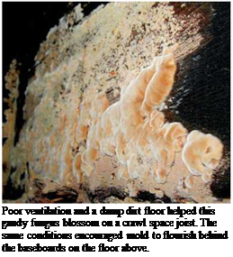
Подпись: Poor ventilation and a damp dirt floor helped this gaudy fungus blossom on a crawl space joist. The same conditions encouraged mold to flourish behind the baseboards on the floor above. Подпись: TIP If you're unsure whether basement-wall wetness is caused by moist interior air condensing or ground water seeping through, try this: Wipe dry a section of wall, then duct tape a 1-ft. by 1-ft. piece of aluminum foil to the dried area. In a day or two, remove the tape and note which side of the foil is wet. 1111 SEALING CRAWL SPACES

Crawl spaces are well named: They tend to be dark, dank, dirt-floored areas only a few feet high. To disperse moisture, building codes pre­scribe 1 sq. ft. of ventilation for each 150 sq. ft. of dirt floor or 1 sq. ft. of vents for every 1,500 sq. ft. of floors covered with a moisture barrier.

Problem is, open crawl spaces mean cold floors and heat loss in winter; and in summer, warm moist air entering through the vents invariably condenses on the cooler surfaces of the crawl space—leading to mold and worse. So it makes more sense to seal and condition crawl spaces.

Otherwise, mold spores growing in the crawl space will be sucked into living spaces by bath and kitchen exhaust fans and carried all up to the attic by the stack effect of rising heated air.

You’ll start by raking the crawl space to remove debris and sharp rocks, which could puncture plastic moisture barriers. But before stirring up crawl space dust and debris, please read the safety alert on p. 334. Heavy sheeting will last longer: 6-mil polyethylene is minimal, but commercial waterproofing firms, such as Basement Systems®, use 20-mil polyester cord-reinforced sheeting, which can withstand workers crawling and objects stored on it. Seal vent openings by gluing 2-in.-thick foam insula­tion over them, using a polyurethane sealant such as Vulkem 116, which is also appropriate for sealing moisture barriers to concrete walls.

In a rectangular crawl space without jogs, it typically takes five large sheets of polyethylene to

Подпись: ALERTПодпись: If rodents have nested in your crawl space or basement, disturbing those nests or breathing contaminated particles may expose you to a number of serious diseases and microorganisms, including Hantavirus, which causes hantavirus pulmonary syndrome, for which there is no vaccine or antivirus. Licensed pest-control firms know the safest means of trapping such pests, preventing their reentry, and removing contaminants. Often, they first moisten the affected areas with a 1:10 bleach solution (also a viricide) to minimize dust, while wearing N-100 respirators and disposable Tyvek suits.Подпись: IlllllПодпись: PROГIP If you pour a concrete slab in a basement or crawl space, place the concrete directly on the polyethylene sheeting. Don't place sand or pea gravel over the plastic before pouring concrete because water collecting on those aggregates would keep the slab damp. llll Подпись: Bath-FanПодпись: Removing moisture is the primary function of a bathroom fan-good to remember when considering all the extra features you could buy. First, get a quiet fan: 3 sones to 4 sones is tolerable, 1 sone is very quiet. Next, consider switches. Because fans usually need to continue venting after you leave the shower, get an electronic switch with an integral timer so the fan can keep running after the light has been turned off. Or put the light and the fan on separate switches. You can also connect the fan to a humidistat, which is a moisture sensor that will turn off the fan when a preset moisture level is reached.Подпись:image696

isolate the space: a single floor sheet which runs about 1 ft. up onto walls; and four wall pieces which overlap at the corners and the floor by 1 ft. and run up the walls to a height 2 in. to 3 in. below the mudsills. (Leave mudsills exposed so they can be inspected periodically.) Because the sheets are heavy, cut them outside on a well – swept driveway, roll them up, and then unroll them in the crawl space. Overlap seams roughly 1 ft., caulking each overlap with polyurethane sealant, and then taping the seams with a com­patible peel-and-stick tape such as Tyvek tape.

Use polyurethane caulk to attach the tops of sheets to the crawl space walls; if the walls are dirty, wire-brush them first to ensure a good seal.

Because the moisture barrier must be contin­uous to be effective, sealing the floor sections becomes more difficult if there are masonry piers or wood posts present. In that case, use two pieces of polyethylene to cover the floor, with each piece running roughly from the base of a post to the crawl space perimeter. Slit the plastic and run it up 6 in. to 8 in. onto each pier; caulk and tape the plastic to the pier. If there is metal flashing under the wood posts, wrap the posts with plastic, too. But if the posts rest directly on masonry pads, jack each post enough to slide a piece of metal flashing or heavy plastic under­neath; otherwise, moisture will wick up through the post and eventually rot it.

The wall portions of the sheeting will be less likely to pull loose if you mechanically attach them toward the top of crawl space walls. If you use sheeting as heavy as a pool liner (20-mil), you can drill holes through it into the concrete and drive in nylon expansion fasteners. Lighter grades of polyethylene can be wrapped several times around furring strips and then attached to walls with a powder-actuated nailing system. (For this, wear eye and hearing protection.) If condensation persists in a sealed crawl space, insulate the walls with rigid-foam panels over the plastic wall sheeting. Finally, add a dehumidifier to condition damp air that gets into the crawl space.

BELLS AND WHISTLES

INSTALLING A BATHROOM FAN

Bathrooms add a tremendous amount of mois­ture to interior spaces. Fortunately, bathroom fans are increasingly powerful and quiet running. And remote inline fans, typically installed in attics some distance above bathrooms, are qui­eter still. Place the fan near the shower, and vent the ductwork from the fan out the roof or through a gable-end wall. Soffit and sidewall vents aren’t as desirable because expelled mois­ture could get drawn up into the attic by a soffit to ridge airflow. Keeping moisture out of attics and wall cavities is crucial, and you can achieve it by airtight connections—by caulking the fan housing to the ceiling and sealing each duct joint with aluminum foil tape, not fabric duct tape.

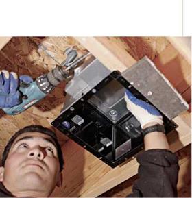
First create a cardboard template of the fan box (housing). Mark the approximate position of the fan by driving a screw or nail through the ceiling before going up into the space above the bathroom and finding the marker. If you have an insulated attic above, take along a dustpan to shovel loose insulation out of the way; wear a dust mask and gloves. After you’ve located the marker, place the fan template next to the nearest joist—most fan boxes mount to ceiling joists— and trace around it. (If the fan box has an adjustable mounting bar, you have more latitude in placing the fan.) Use a jigsaw or reciprocating saw to cut out the opening. To keep the drywall cutout from falling to the floor below, screw to the drywall a piece of scrap wood slightly longer than the cutout.

To mount the fan housing, you may need to remove the fan assembly first. If the housing
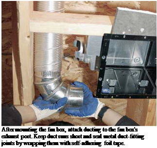
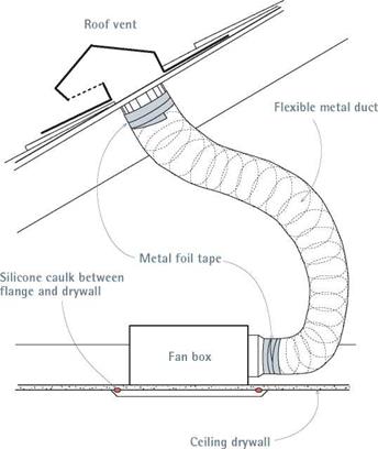
Подпись: After mounting the fan box, attach ducting to the fan box's exhaust port. Keep duct runs short and seal metal duct-fitting joints by wrapping them with self-adhering foil tape.
Подпись: To keep moisture from leaking into the attic, apply silicone caulk between fan box flanges and mating surfaces, such as drywall. To ensure airtight joints, use metal foil tape to seal ducting to the fan's exhaust port and to the roof vent or sidewall vent.

Подпись: There are complex formulas for sizing bath fans, but a good rule of thumb is 1 cfm (cubic foot per minute) per square foot for bathrooms 100 sq. ft. and smaller. For bathrooms larger than that, allot 50 cfm for each fixture (toilet, lav, shower), and allow 100 cfm for hot tubs.Подпись: llllimage698

flange mounts flush to the underside of the ceil­ing, as shown in the photo at left, use a piece of drywall scrap to gauge the depth of the unit rela­tive to the finish ceiling. But whether the housing flange sits above or below the ceiling drywall, caulk the flange well with polyurethane sealant to create an airtight seal between the two materials. To further secure the fan and anchor the edges of the drywall opening, run blocking between the joists—along two sides of the opening—and screw the drywall to the blocking. In some cases, you’ll be screwing through the fan’s housing flanges as well.

Follow the wiring diagrams provided by the manufacturer. In general, it’s easier to run electri­cal cable through a switch box first because junc­tion boxes inside fan housings tend to be cramped. Bathroom fans should be protected by a GFCI (ground-fault circuit interrupter); see Chapter 11 for more information.

Keep duct runs as short as possible to reduce air resistance. After attaching the lower end of the flexible duct to the fan’s exhaust port and sealing the joint with metal duct tape, hold the free end of the duct to the underside of the roof sheathing (or gable-end wall) and trace its out­line onto the sheathing. Drive a screw through the middle of the circle. Then go outside and locate the screw, which represents the middle of the vent hole you need to cut. Sketch that circle onto the roof: If the circle would cut into the tabs of any shingle—roughly the bottom half of a shingle strip—use a shingle ripper (see the left photo on p. 121) to remove those shingles before cutting the vent hole in the sheathing. Be gentle when removing shingles so you can reuse them.

Use a utility knife to cut the circle into any remaining shingles and the roofing paper. Flash the fan’s roof vent as you would any other roof vent: Feed its upper flange under the shingle courses above and over the courses below. Caulk or nail the flange edges per the installation instructions and renail the surrounding shingles. Once the roof vent is flashed, go back under the roof and attach the free end of the duct, also seal­ing that joint with metal duct tape. Enjoy your shower.

LEAKY DUCTWORK

Because ductwork usually runs through basements or uncondi­tioned crawl spaces, sealing it will reduce heat loss and sub­floor moisture being drawn into living areas. Leaky ducts can waste 25 percent to 30 percent of total heating/cooling costs. Sup­ply ducts most often leak where they take off from the main sup­ply trunk, at section joints, and where ducts join register boots. Ironically, many leaks are caused by fabric duct tape that has dried out and cracked after a few years. Even if it looks intact, remove fabric duct tape.

Sealing Ducts

Living space

Register boot

image690

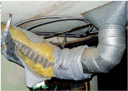
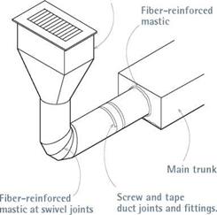
Secure joints between duct sections and fittings with at least three sheet-metal screws. Then wrap the joints with aluminum duct tape—not fabric duct tape! Apply fiber-reinforced mastic to hand – snipped and swivel joints.

There are three ways to reduce duct heat loss. Apply aluminum duct tape to joints between sec­tions and to the factory-formed joints where round ducts snap together. Along hand-snipped or swivel joints, which aren’t as airtight, seal ducts with fiber-reinforced mastic, which you can apply generously to joints, using a brush or your hand (wearing disposable plastic gloves). Finally, to further reduce heat loss and condensa­tion, insulate ducts in unconditioned spaces. Wrap l-in.-thick, foil-backed batts around the outside of the ducts; avoid interior duct linings such as ductboard, which can reduce airflow, absorb moisture, and grow mold.

WEATHERSTRIPPING AND CAULKING

Weatherstripping can reduce air leaks around doors and windows. Door weatherstripping is discussed in Chapter 6; two of the more popular types, tubular and metal-leaf, are also appropri­ate for windows. Install tubular weatherstripping for casement or awning windows, which are hinged as doors are and thus will seat solidly against compressible stripping. Metal-leaf strip­ping offers a tighter seal for double-hung win­dows, but installing it requires removing interior stops and possibly planing down sashes.

Interior door and window casing may leak air if there’s not a good paint seal to surrounding

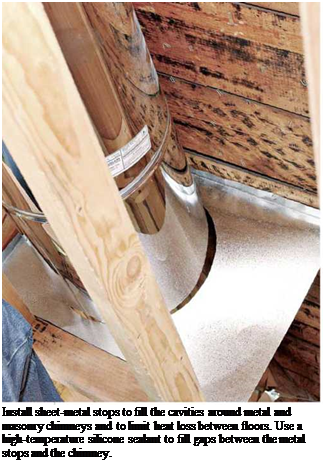
Подпись: Install sheet-metal stops to fill the cavities around metal and masonry chimneys and to limit heat loss between floors. Use a high-temperature silicone sealant to fill gaps between the metal stops and the chimney.
Подпись: spaceimage692walls. If you notice gaps or cracks around the perimeters of the casing, caulk them with acrylic latex caulk, which you can tool smooth with an index finger. (Wash up with warm, soapy water.) Allow the caulk to cure before painting it.

Gaps around exterior casing are most com­mon on south-facing walls, where the sun is strongest. Typically, wood trim shrinks across its width, creating gaps where siding abuts. Fill gaps with exterior acrylic latex or siliconized latex caulk. (Pure silicone caulks don’t paint well, and many polyurethane caulks have poor UV resist­ance.) Because caulking alone is not terribly durable, paint it as soon as it has cured. To effec­tively block air and moisture infiltration, the edges of door and window frames should be caulked, flashed, recaulked (over flashing strips), and then recased, as shown on p. 129.

AIR AND MOISTURE RETARDERS

Any building material that is sufficiently imper­meable to slow the flow of air and airborne mois­ture is considered an air-flow retarder, even if that’s not its primary function. If a retarder is installed specifically to stop water vapor, it’s called a vapor barrier. Most houses have both interior and exterior air-flow retarders: house – wrap or building paper, flashing, sheathing and siding on the outside, and drywall or plaster

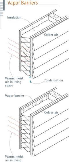
In cold and very cold climates, polyethylene vapor barriers on the living-space side of insulation may prevent water vapor from condensing inside walls, which can lead to peeling paint, mold, and, in extreme cases, rotted framing.

inside. (Housewraps such as Tyvek are semi­permeable: They keep rain out but allow water vapor trapped in walls to migrate outward.)

Some insulation, such as high-density cellulose and polyurethane foams, can be considered air­flow retarders, as discussed later in this chapter.

Подпись: TIPПодпись: If windows rattle when the wind blows, remove and reset the interior stops snugly to the window sashes before weatherstripping windows. In moderate climates, tight-fitting sashes will cut air infiltration significantly. 1111 In cold and very cold climates, there should be a polyethylene vapor barrier installed on the living-space side of the insulation to prevent warm, moist air from migrating into wall cavities and condensing there during cold weather. Several things to note about vapor barriers: To be effective, they must be continuous—no gaps or
Solid Mechanics

On the one hand, solid mechanics can be modelled on the following basis. The equilibrium equation is:

дг <jjj + Pj = 0 (11.1)

Where Pj is a member of P, the vector of volume forces, ji;- is a member of j, the Cauchy stress tensor, and д represents the spatial partial derivative operator:

di = (11.2)

dXi

The stress tensor is obtained by the time integration of an (elastic, elasto-plastic or elasto-visco-plastic) constitutive equation (see Chapter 9, Section 9.4.2; Laloui, 2001; Coussy & Ulm, 2001):

Jij = fn(j, e, Z) (11.3)

where (jij is the stress rate, e is the strain rate and Z is a set of history parameters (state variables, like e. g. the preconsolidation stress). In the most classical case of elasto-plasticity, this equation reduces to:

jч = hi

where Eejkl is a member of the elasto-plastic constitutive (stress-strain) tensor, Eep. Most constitutive relationships for geomaterials are non-linear ones and not as pre­viously introduced in Eq. 9.1 in a linear version.

When modelling a solid mechanics problem with the finite element method, the most commonly used formulation is based on displacements that make up the vector l or on actual coordinates that make up the vector x. If one considers only small strains and small displacements, the strain rate reduces to the well-known Cauchy’s strain rate:

Sij — 2 (djlj + djli) (11.5)

The time dimension is not addressed for solid mechanics problems, except when a viscous term is considered in the constitutive model. Generally, the time that ap­pears in the time derivatives inEqs. 11.3, 11.4 and 11.5 is only aformal one.

Hinge Requirements

Multiple sign supports are designed to operate correctly when either one or all of the sup­ports within a 7-ft (2100-mm) radius are impacted. When only one support is impacted, the remaining signpost should support the sign and prevent it from penetrating the wind­shield. The desired impact performance of slip base and frangible coupler designs for large sign supports is depicted in Fig. 7.29. The base releases upon impact and the impacted support rotates up, allowing the vehicle to pass underneath the sign. This requires that the post be cut, at least 7 ft (2100 mm) above the ground, to provide a hinge for rotation.

TABLE 7.14 Details of Concrete Foundation Design for Large Slip Bases

a.

Details in U. S. Customary units

Post size,

Stub

Stub

Drilled shaft

A615M bar

in X lb/ft

length

projection, in

diameter

size, no.

S3 X 5.7

1′-6"

3K

1′-6"

5

S4 X 7.7

1′-6"

3/2

1′-6"

5

W6 X 8.5

2′-0"

3

2′-0"

5

W6 X 12

2′-0"

3

2′-0"

5

W6 X 15.5

2′-6"

3

2′-0"

6

W8 X 17

2′-6"

3

2′-0"

7

W8 X 20

3′-0"

2/2

2′-0"

8

W10 X 21

3′-0"

2/2

2′-0"

9

W10 X 25

3′-0"

2/2

2′-0"

10

W12 X 27

3′-0"

2/2

2′-0"

11

b. Details in SI units

Post size,

Stub

Stub

Drilled shaft

A615M bar

mm X kg/m

length, mm projection, mm

diameter, mm

size, no.

S76 X 8

460

90

460

15

S100 X 11

460

90

460

15

W150 X 13

600

75

610

15

W150 X 18

600

75

610

15

W150 X 23

760

75

610

20

W200 X 25

760

75

610

25

W200 X 30

910

65

610

25

W254 X 31

910

65

610

30

W254 X 37

910

65

610

35

W305 X 40

910

65

610

35

As shown in Fig. 7.30 and discussed in Art. 7.5.3, hinges for large sign supports consist of three basic designs: (1) partially cut post with front friction plate, (2) completely cut post with front friction and rear hinge plate, and (3) completely cut post with weakened front plate and rear hinge plate. Proper performance of the hinge requires the correct selection of plate size, bolt size, and torque. Figure 7.51 and Table 7.16 present the design values for friction plates. Figure 7.52 and Table 7.17 present the design values for hinge plates. The bolt torque values for both friction and hinge plates are the same as presented as Table 7.15 for slip bases. Proper sized flat washers should be used under each nut and the head of each bolt.

The hinge systems shown in Fig. 7.30 are all unidirectional designs and should not be used in areas requiring bidirectional breakaway performance. Only the Transpo hinge system shown in Fig. 7.31 offers bidirectional breakaway capability.

Introduction – Problems to be Treated

When trying to replicate in-situ behaviour by computational techniques, a number

of different physical phenomena (Gens, 2001) need to be considered, including:

• The non-linear solid mechanics and especially granular unbound or bound mate­rial mechanics: we consider the relations between displacements, strains, stresses and forces within solids. The material behaviour is described by a constitutive model, which can take into account elasto-plasticity or elasto-visco-plasticity;

• The fluid flow within porous media: fluid can be a single phase of various na­tures (water, air,…) or it can be an association of two fluids, leading to unsat­
urated media (water and air,…). In the second case, partial saturation leads to permeability and storage terms depending on the saturation degree or on the suction level, involving non-linear aspects;

• The thermal transfers within porous media: conduction is the leading process in a solid (in the geomaterial matrix), but convection can also occur in the porous volume, as a consequence of the fluid flow. Radiation transfer could also occur inside the pores, but it will be neglected here. Conduction coefficients and latent heat may depend on the temperature; and

• The pollutant transport or any spatial transfer of substance due to the fluid flow: the pollutant concentration may be high enough to modify the densities, involv­ing non-linear effects.

All these problems are non-linear ones, and can be formulated with sets of partial

differential equations. However, only three types of differential equations have to be

considered, concerning respectively:

i) solid mechanics;

ii) diffusion; and

iii) advection-diffusion problems.

Modelling Coupled Mechanics, Moisture and Heat in Pavement Structures

Robert Charlier[25], Lyesse Laloui, Mihael Brencic, SigurSur Erlingsson, Klas Hansson and Pierre Hornych

Abstract Different physical problems have been analysed in the preceding chapters: they relate to water transfer, to heat transfer, to pollutant transfer and to mechanical equilibrium. All these problems are governed by differential equations and boundary conditions but analytical solutions are, in general, unobtainable because of the com­plex interaction of the various aspects which are always present in real-world situ­ations. In such circumstances, numerical modelling can give a valuable alternative methodology for solving such highly coupled problems. The first part of this chapter is dedicated to a brief statement of the finite element method for highly coupled phenomena. In the second part, a number of numerical simulations are summarised as an illustration of what could be done with modern tools. The chapter shows that it is possible to achieve realistic results although, at present, some simplification is often required to do so.

Keywords Finite element method ■ multi-physics coupling ■ partial differential equation ■ examples of applications

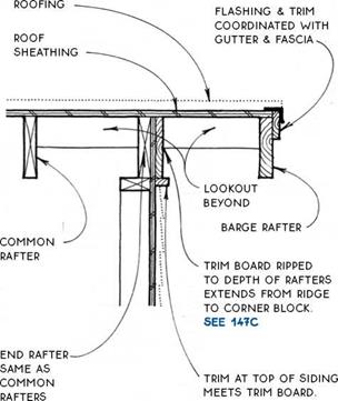
EXPOSED RAKE WITH VERGE RAFTER

Section

COMMON RAFTER


end rafter same as common

RAFTERS


EXPOSED RAKE WITH VERGE RAFTER

FASCiA SQUARE CUT (AS SHOWN) & COVERED WiTH BARGE TRiM, oR MiTERED To barge RAFTER


BARGE

RAFTER


corner of walls


EXPOSED RAKE WITH VERGE RAFTEREXPOSED RAKE WITH VERGE RAFTER

Concluding Remarks

This Chapter presents in-situ and laboratory experimental techniques used to de­scribe mechanical behaviour of pavement materials (soils and aggregates) at dif­ferent saturation stages. Repeated triaxial load testing can be applied to obtain both stiffness characteristics and assessments of the ability of the material to with­stand accumulation of permanent deformation during cyclic loading. For unsatu­rated soils, in addition to mechanical variables, a moisture/suction control should be added, which can be imposed by several techniques as explained in the chapter. A brief presentation of the model parameters and tests needed for model calibration was introduced with particular reference to the modelling approaches described in Chapter 9. Evaluations of pavement structural capacity based on deflection mea­surements with non-destructive testing equipment have also been presented. Finally, some examples of laboratory and in-situ measurement are shown.

Fig. 10.23 Soil suction measured with tensiometers and saturation measured with the mois – ture/density probe (Krarup, 1995). Reproduced by permission of the Danish Road Institute Note: Where measurements were carried out at different depths, the depths of the tensiometer are given in brackets (69 cm). The curves are time series beginning from the left (high suction).

Based on experimental results presented above it can be concluded as follows:

i) Bearing capacity and unconfined compressive strength decrease with increase in moisture content.

ii) The permanent axial strain increases when water content approaches to wOPM.

iii) Resilient modulus decreases as the water content approaches to wOPM. The resilient modulus of soils decreases by a factor 4-5, for realistic (temperate) seasonal variation of moisture contents.

iv) Reduction in resilient modulus with suction depends also on the grading coeffi­cient: lower grading parameters (i. e. more fine particles) yields larger modulus reductions as saturation is approached.

v) In-situ experimental data confirms that resilient moduli decrease with decrease in suction. The soil-water characteristic curve depends on the grading of tested material meaning that the modulus-suction relationship is likely to be very soil- specific.

Energy Conservation and Air Quality

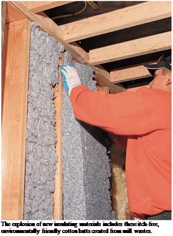
Подпись: The explosion of new insulating materials includes these itch-free, environmentally friendly cotton batts created from mill wastes.

Controlling the

ture, and heat determines how comfortable, affordable, and durable a house will be. In the old days, houses were often drafty and cold, but because energy was cheap homeowners could compensate by throwing another log into the woodstove or by cranking up the thermostat. All that changed in the 1970s, when energy costs went through the roof. . . literally, in houses with uninsulated attics. In response, builders yanked fuel-guzzling furnaces and replaced leaky doors and windows with tight, factory-built ones. They also caulked gaps; installed weatherstripping; and insulated walls, floors, and ceilings to block drafts (infiltration) and slow the escape of condi­tioned air (exfiltration). This insulated layer between inside and outside air is called the ther­mal envelope.

Although tightening the thermal envelope saved energy, it spawned a whole new set of prob­lems, including excessive interior moisture, peel­ing paint, moldy walls, rotted studs, and a buildup of pollutants that were never a problem when windows rattled and the wind blew free. In many houses, furnaces no longer had enough incoming air to burn fuel or vent exhausts effi ciently. In some super-tight houses today, turning on a bathroom fan or a range hood can even cre­ate enough negative pressure to pull exhaust gases back down the chimney (back-drafting) and suck mold spores up from dank crawl spaces.

Fortunately, this chapter can help you control the flow of air, moisture, and heat while balanc­ing comfort, costs, and health concerns. Because HVAC (heating, ventilation and air conditioning) systems have become incredibility sensitive and complex, installing and adjusting them is best left to HVAC specialists. If you want information on designing and constructing energy-efficient houses, consult Joe Lstiburek’s Builder’s Guide to Mixed Climates or Builder’s Guide to Cold Climates (both The Taunton Press).

Sealing Air Leaks

Retaining conditioned air is tricky, even in well – insulated houses. As air is heated, it rises and expands, pushing against the inside of the ther­mal envelope. If it finds holes or gaps in the enve­lope, it escapes. Likewise, winter winds can drive cold air into a building. In new construction, air­flow retarders such as housewrap are installed in large sheets on exterior walls before the siding is put on. Or inside walls are insulated and covered with polyethylene vapor barriers before the dry-

wall goes up. However, where siding and drywall are already in place, sealing air leaks is largely a piecemeal affair of locating and caulking leaks, one gap or hole at a time.

LOCATING AIR LEAKS

Professionals use powerful blower-doors to depressurize interiors and thereby draw-in huge volumes of air to help locate leaks. But during the heating season, you can find most leaks your­self with a wetted finger, a smoking incense stick, and common sense. Begin by running your hand around window and door frames and along room
corners. If your house has leaks, you’ll feel drafts, especially if it’s cold and windy outside. The incense smoke will also show where warm air is leaving the building. But common sense is the best detector.

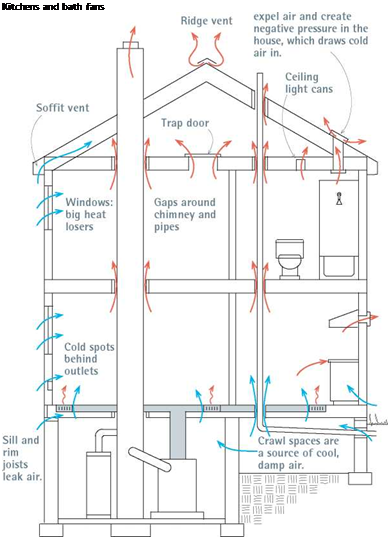
Подпись: I How Air Moves through a HouseПодпись:Подпись:

Подпись: How Heat Moves Heat is transferred by one of three mechanisms: radiation, conduction, or convection. Radiation is the movement of heat through space, in the form of infrared waves; heat and light waves radiate in all directions from a central source, such as the sun or a hot stove. Conduction is the passing of energy from particle to particle, usually between objects touching each other, as when a stovetop burner touches a tea kettle. Convection is the transfer of heat or cold by the movement of air, with warmer air rising and cooler air descending. Heat transfer in houses is usually a combination of all three mechanisms. For example, sunlight radiates into a room and heats a dark tile floor. A cat lying on the floor receives radiant heat from the sun and conductive heat from the floor. And even in a room where the air seems still, there will be convective loops as warmed air rises from warmed floors and heat vents, and falls near cold windows. As likely, there will also be convective heat loss—that is, air moving through walls can account for 20 percent to 30 percent of the total heat loss of an insulated house. Building materials conduct heat at different rates. The more resistance a material has to heat transference by conduction, the higher its resistivity value, or R-value. In general, the less dense the material, the better insulator it is and the higher its R-value. And the denser the material, the better it conducts heat or cold and the poorer it is as an insulator. Thus dense masonry materials tend to be poor insulators, wood intermediate, and fluffy cellulose fibers excellent. Glass, being very dense, is an excellent conductor but a poor insulator. Thus glass windows, even double- or triple-paned ones, lose a lot of heat, compared to other building materials.

Heated air rises, so start your detective work in the attic. If it’s uninsulated, you’ll see plumbing ducts, electrical cables, recessed lighting cans, heating and fan ducts, chimneys, and a host of other penetrations in the attic floor through which heated air is escaping. If there’s an old

plaster ceiling below, there may also be a lot of heat loss through cracks. Especially note bath – or kitchen-fan vents that terminate in the attic. They should be vented outside, rather than into the attic, because the moist air they pump into an attic can condense there, soaking insulation, fram­ing, and drywall—creating a paradise for mold and rot (see the photo on p. 12).

After investigating the attic, go downstairs and examine ceilings for cracks, cold spots, and mold. Frequently, corners on exterior walls will be cold because insulation stops short of fram­ing. Or insulation may have slumped at the tops of walls. Continue down the walls, noting drafts or gaps around windows and doors—especially under doors—and cold spots around electrical receptacles and switches on exterior walls. Com­mon walls between houses and attached garages are frequently underinsulated, and openings there can allow car exhaust and volatile fumes to infiltrate living spaces. Check local building codes: Most require fire-resistant drywall and fire­stopping caulks on common walls with garages.

Finally, inspect basements and crawl spaces. Caulk gaps between framing and foundations, and use rigid-foam panels to insulate basement walls. Conventional wisdom long held that out­side air should circulate freely through dirt – floored crawl spaces. But as house envelopes grew tighter, scientists determined that the nor­mal pressurization of heated air and negative
pressures from exhaust fans routinely pull moist, often mold-laden crawl space air up into living areas. Consequently, engineers now recommend sealing, insulating, and conditioning crawl spaces, especially in hot, humid regions, as explained later in this chapter.

FIXING LEAKS

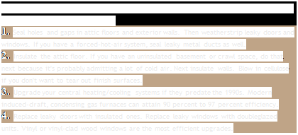
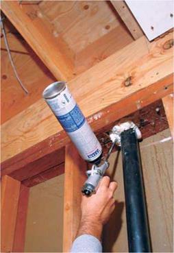
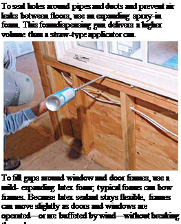
Подпись: PrioritiesПодпись: SPENDING TO SAVE ENERGY:Подпись: If your budget is tight, weatherize your house and upgrade its systems in this order (each is explained in detail in this chapter): 1. Seal holes and gaps in attic floors and exterior walls. Then weatherstrip leaky doors and windows. If you have a forced-hot-air system, seal leaky metal ducts as well. 2. Insulate the attic floor. If you have an uninsulated basement or crawl space, do that next because it's probably admitting a lot of cold air. Next insulate walls. Blow in cellulose if you don't want to tear out finish surfaces. 3. Upgrade your central heating/cooling systems if they predate the 1990s. Modern induced-draft, condensing gas furnaces can attain 90 percent to 97 percent efficiency. 4. Replace leaky doors with insulated ones. Replace leaky windows with doubleglazed units. Vinyl or vinyl-clad wood windows are the most efficient upgrades. Polyurethane sealants are the best bet for filling gaps around door and window frames, electrical cable, water pipes, and plumbing vents. These sealants are typically expanding spray-in foams,
Energy Conservation and Air Quality

DIFFERENT JOBS, DIFFERENT FOAMS

image687Подпись:PRO"ГIP

If the attic is insulated, you’ll need to put on gloves and a face mask and move that insulation before you can seal openings in the attic floor. But don’t merely cuss those batts; examine them. Fiberglass batting actually filters dirty air, so look for blackened areas on the undersides of batts, where heated air has blown through ceiling cracks into the attic.

1111

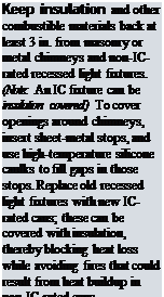
Подпись: ALERTПодпись: Keep insulation and other combustible materials back at least 3 in. from masonry or metal chimneys and non-IC-rated recessed light fixtures. (Note: An IC fixture can be insulation covered.) To cover openings around chimneys, insert sheet-metal stops, and use high-temperature silicone caulks to fill gaps in those stops. Replace old recessed light fixtures with new IC-rated cans; these can be covered with insulation, thereby blocking heat loss while avoiding fires that could result from heat buildup in non-IC-rated cans.Подпись: IlllllПодпись:image689

available in 12-oz. to 33-oz. aerosol cans with straw-type applicators for incidental home use. Contractors often use screw-on cans designed for dispenser guns. High-volume pros attach 10-lb. to 16-lb. disposable cylinders to pneumatic dispensers.

Foams vary in many ways, including durabili­ty, temperature ranges, curing times, fire resist­ance and—most notably—expandability. Read the product literature carefully. As handy as foams with 700 percent expansion would be to fill large gaps, they could buckle door frames badly. To seal gaps around doors and windows, instead select a low-pressure or mild-expanding foam sealant. Expandable latex polymer foams are gaining popularity because, like latex caulk, they clean up with soap and water before they’ve cured.

Because gaps between foundations and fram­ing can involve high humidity, great temperature shifts, and dissimilar materials, acrylic latex or silicone caulks may be more appropriate to seal air leaks in basements and crawl spaces. If gaps are wider than й in., stuff foam backer rod into the gaps before caulking. Important: If the house has mouse or rat problems, stuff larger holes or cracks with й-in. galvanized mesh before spray­ing foam into gaps. Rodents will chew through foam, so place the mesh toward the house exterior.

If you find holes too big for expandable foams, stuff plastic garbage bags full of insula­tion and jam the bags into the openings. Or cover the opening with a sheet of rigid-foam insulation or a piece of plywood, and seal the edges with spray-on foam. Don’t forget uninsulat­ed attic hatch covers: Use construction adhesive to glue a 3-in.-thick piece of Styrofoam®

(or two 2-in.-thick panels) to the upper face of the hatch.

SEALING