USING DRYWALL CLIPS TO SECURE. THE ENDS OF DRYWALL SHEETS
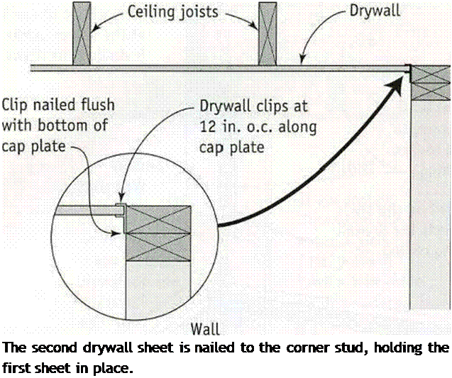
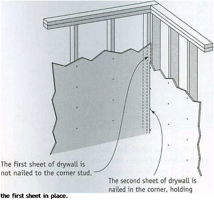
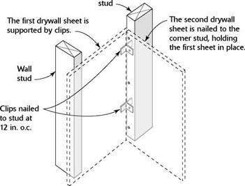
Подпись: The second drywall sheet is nailed to the corner stud, holding the first sheet in place. Подпись: Drywall clips eliminate the need for backing at intersecting walls and on cap plates.USING DRYWALL CLIPS TO SECURE. THE ENDS OF DRYWALL SHEETSПодпись: N N. Подпись: чpaper-faced insulation; it’s designed to affix drvwall to a wood surface. Follow the applica­tion and installation instructions on the label.

Corner details

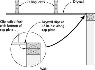
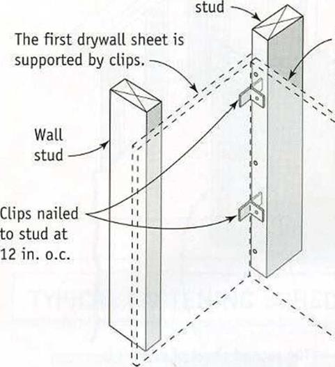
If you provided backing or deadwood while building interior walls (see chapter 4) and installing roof trusses (see chapter 5), you’ll be able to drive nails or screws along the walls to fasten drywall panels. But if solid backing material for drywall was not nailed to the tops of parallel walls or in the corners where walls intersect, metal drywall clips can be used instead. See the illustration at right for instructions on using these clips. Unlike a dry – wall corner secured with nails or screws, a cor­ner secured with clips can be more resistant to cracking when the framing material moves in response to temperature fluctuations.

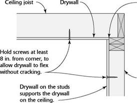
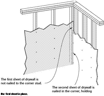
Another strategy is to let the corner “float,” eliminating nails where a ceiling panel meets the wall. The top edges of wall panels are then pushed snugly against the ceiling panels, holding them in place (see the illustration on p. 224). Again, this can help prevent corner cracks at the ceiling-wall juncture due to wood shrinkage or truss uplift. If you’re uncertain about how to handle drywall corners, check with experienced builders in your area.

Once all the ceiling panels are in place, run a bead of caulk where the ceiling panels butt

USING DRYWALL CLIPS TO SECURE. THE ENDS OF DRYWALL SHEETS
USING DRYWALL CLIPS TO SECURE. THE ENDS OF DRYWALL SHEETS USING DRYWALL CLIPS TO SECURE. THE ENDS OF DRYWALL SHEETS

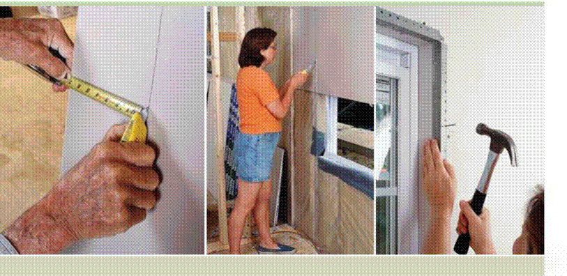
Cutting drywall isn’t difficult, once you learn how to score through the paper covering with a utility knife. . .

The panels have a gypsum core that makes them heavy and delicate. They create a lot of dust, too, especially when making cuts with a saw. . .

Covering the studs with drywall provides our first look at real rooms. . .

The metal corner bead looks ugly until it is covered with drywall compound, which we call mud.

USING DRYWALL CLIPS TO SECURE. THE ENDS OF DRYWALL SHEETS

CREATING A FLOATING DRYWALL JOINT

Подпись: On exterior walls, prevent air infiltration with a bead of caulk at the corner before installing the drywall.Подпись: Wall studUSING DRYWALL CLIPS TO SECURE. THE ENDS OF DRYWALL SHEETSПодпись:Подпись: іПодпись:Подпись: Panel offcuts come in handy. Use the cut-off ends of panels to cover small spaces, such as closet interiors, window trimmers, and closet doorways. Don't overdo it, though. Using too many small pieces creates extra work when it's time to tape and mud the joints.

the exterior walls to reduce air infiltration (see the illustration above). I finish the ceiling by marking the location of wall studs with a small pencil mark on the ceiling drywall. These marks help when nailing drywall to the walls. Don’t use keel on drywall (unless it is covered with drywall tape) because it can bleed through paint.

STEP 3 Install the Wall Panels

Hanging drywall on the walls is easier than hanging them on the ceiling. You have to work around window and door openings, and there are more electrical outlet openings to mark and cut, but you don’t have to work overhead. Its important to know that some electrical wires (for the thermostat, doorbell, range hood, and so on) will not be enclosed in a box. Electricians often wrap those wires around a nail to locate their position. All you need to do is make a small hole in the drywall and pull the wires through.

Enesti

The Enesti, or NST (not so tiny), contains two bedrooms, one-and a-half baths, a fireplace, a dining nook, ample storage and a full kitchen that includes a washer/ dryer beneath the counter. A third bedroom is also available.

ГТ1ТЛ

L£L±J

1 1

1 1 1

1 1

1 1 І

1 1

1 1 1

1 1

1 і •

Square feet: 681

With add-on: 774 House width: 24’

House length: 22’

Porch: 6’ x 18’

Great Room: 9%’ x 15%’ Kitchen: ІУ2 x 9%’

Bathroom: 5%’хб’

Half Bath: 41/2’ x 5’

Addition: 7’x12’

Ceiling height: 7’ 6”

-sizes are approximate

STRAIGHT COUNTER, NO SINK

The simplest surface to lay out is a straight counter with no sink because it has only one con­trol line. Begin by using a framing square and a story pole to survey the countertop.

“Counter Layout,” on p. 398, assumes that the counter edges are finished with V-cap trim, a

image816Подпись: COUNTER WITH SINK OR COOKTOPПодпись:image817

I Counter Layout

A straight counter needs only one layout control line to indicate the first tile joint back from the edge.

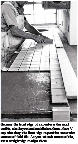
common choice, and tile joints are Vs in. wide. Place several V-caps along the counter edge; then measure back from the edge & in. from each cap to mark the middle of the first grout joint. Snap a chalkline through these marks to establish a con­trol line. Because the front edge is the counter’s focal point, you’ll place full field tiles next to the row of V-caps.

Using your story pole, measure the length of the counter to see if you must cut tiles. If one end of the counter abuts a wall and the other is open, plan a row of full tiles along the open end, thus consigning cut tiles to the wall end where they’ll be less conspicuous. If both ends of the counter are open, and you see that you’ll need to cut tiles, move the story pole so that cut tiles will be the same dimension on both ends. That decided, mark positions for the tile units along the control line.

Last, measure to the back of the counter to determine whether the final row of tiles will need cutting. You can precut tiles; but on a counter so simple, you can just measure and cut partial tiles individually after all the full tiles are set, likely giving you more accurate measurements anyway.

Подпись: FROM THE ARCHIVESПодпись: Because the front edge of a counter is the most visible, start layout and installation there. Place V-cap trim along the front edge to position successive courses of field tile. As you set each course of tile, use a straightedge to align them. If a sink or a cooktop in the counter interrupts the layout and requires tile cutting, mark secondary control lines on either side to indicate where full tiles resume.

L-SHAPED COUNTER

image819

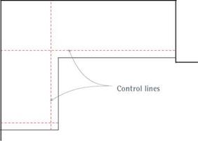
An L-shaped counter will have two major control lines, running perpendicular to each other. Add lines as needed to indicate sink placement, open counter edges, and so on.

Basic probability rules for system reliability

The solution approaches to system reliability problems can be classified broadly into failure-modes approach and survival-modes approach (Bennett and Ang, 1983). The failure-modes approach is based on identification of all possible fail­ure modes for the system, whereas the survival-modes approach is based on the all possible modes of operation under which the system will be operational. The two approaches are complementary. Depending on the operational char­acteristics and configuration of the system, a proper choice of one of the two approaches often can lead to significant reduction in efforts needed for the re­liability computation.

Подпись: pf ,sys Подпись: P (F1 U F2 U---U FM) = P Подпись: M U Fm n=1 Подпись: (7.1)

Consider that a system has M components or modes of operation. Let event Fm indicate that the mth component or mode of operation is in the failure state. If the system is a series system, the failure probability of the system is the probability that at least one of the M components or modes of operation fails, namely,

in which pf, sys is the failure probability of the system. On the other hand, the system reliability ps, sys is the probability that all its components or modes of operation perform satisfactorily, that is,

ps, sys = P(F1 n F2 n-.-n FM) = p( n F^ (7.2)

m=1 J

in which Fm is the complementary event of Fm indicating that the mth compo­nent or mode of operation does not fail.

In general, failure events associated with system components or modes of op­eration are not mutually exclusive. Therefore, referring to Eq. (2.4), the failure

probability for a series system can be computed as

n M M_1 M

Подпись: Pf ,sys = PmUi Fm) = £ P(Fm) _^ X) P(Fi, F,)

‘ m=1 i = l j =i + 1

+ EEE P (Fi, Fj, FA ) -… + (-1) MP (Fi, F2,…, Fm ) (7.3)

i< j < Л

According to Eq. (2.7), the reliability for a series system is

Ps, sys = P (F1) X P (F2 | F1) X P (FjJ | F1, F-2) X ••• x P (FM | F1, F-2,…, FM_1)

(7.4)

In the case that failure events Fm’s are mutually exclusive or the probability of joint occurrence of multiple failures is negligible, the failure probability of a series system can be easily obtained as

M

Pf, SyS = £ P(Fm) (7.5a)

m=1

with the corresponding system reliability

M

ps, sys = 1 _ pf, sys = 1 ^ ] P (Fm) (7.5b)

m=1

Under the condition that all failure events are statistically independent, the reliability of a series system can be computed easily as

MM

Ps, SyS = П P(Fm) HI [1 _ P(Fm)] (7.6a)

m=1 m=1

with the corresponding system failure probability

M

Pf, SyS = 1 _П [1 _ P(Fm)] (7.6b)

m=1

The component probability P(Fm) can be determined by methods described in Chaps. 4, 5, and 6 of this book.

Example 7.1 Consider a series system consisting of M independent components, each with an identical component reliability of ps. The system reliability, according to Eq. (7.6a), is

n – PM

Ps, sys = P s

Figure 7.4 shows the relationship among the reliability of a series system, component reliability, and the number of components. As can be seen, the reliability of a series system decreases as the number of components increases.

Basic probability rules for system reliability

Basic probability rules for system reliability

Figure 7.4 Relationship among reliability of a series system, component reliability, and the number of components.


In the case of a parallel system, the system would fail if all its components or modes of operation failed. Hence the failure probability for a parallel system is

Pf, sys = P(F1 n F2 П—П Fm) = P П Fm (7.7)

m=1

The reliability of a parallel system, on the other hand, is the probability that at least one of its component or modes of operation is functioning, that is,

Ps, sys = P (F1 U F2U-.-U FM) = P U Fm (7.8)

m=1

Hence, under the condition of independence for all failure events, the failure probability of a parallel system simply is

M

Подпись: (7.9a)Подпись: (7.9b)pf, sys = П P (Fm)

m=1

with the corresponding system reliability being

Подпись: MM

Ps, sys = 1 – П P (Fm) = 1 – П [! – P (Fm)]

Подпись: m=1m=1

Example 7.2 Consider a parallel system consisting of M independent components, each with an identical component reliability of ps. The system reliability, according to Eq. (7.9b), is

Ps, sys = 1 – (1 – Ps )M

Figure 7.5 shows the relationship among reliability of a parallel system, component reliability, and the number of components. The figure indicates that the reliability of a parallel system increases as the number of components increases.

Basic probability rules for system reliability

No. of components or operational modes

Figure 7.5 Relationship among reliability of a parallel system, component reliability, and the number of components.

For mutually exclusive failure events, reliability of a parallel system can be computed as

M M

Pssys = P (Fm) = M – P(Fm) (7.10a)

m=1 m=l

with the corresponding system failure probability

M

Pf, sys = 1 + P (Fm) – M (7.10b)

m=l

Unfortunately, for a real-life system involving multiple components or modes of operation, the corresponding failure events are neither independent nor mu­tually exclusive. Consequently, the computation of exact values of system reli­ability and failure probability would not be a straightforward task. In practical engineering applications, bounds on system reliability are computed based on simpler expressions with less computational effort. As will be seen in the next subsection, to achieve tighter bounds on system reliability or failure probability, a more elaborate computation will be required. Of course, the required preci­sion for the computed system reliability is largely dependent on the importance of the satisfactory performance of the system under consideration.

Thinset Adhesive

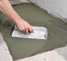
Once you’ve snapped layout lines and vacu­umed the setting bed one last time, use the straight edge of a notched trowel to spread thinset adhesive. Then, using the notched edge of the trowel, comb ridges into the adhesive.

As you apply and comb adhesive, try to stop just short of the layout lines, so you don’t bury them under adhesive.

image812

‘ Л

2.

Installing a Floor

Using a framing square and a tape measure, check to be sure the room’s corners are square and parallel. Make a quick sketch of the room, showing which way corners diverge. Or sketch this directly onto the setting bed.

FLOOR LAYOUT

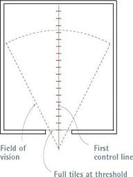
Floor layout begins by identifying the focal point of the room, and snapping two chalklines (con­trol lines) onto the setting bed, perpendicular to each other. In the photos on these two pages, the doorway is the focal point of the room. Thus, the first control line will run through the middle of that doorway and continue across the room till it hits the opposite wall at roughly a right angle.

Full tiles look best in a doorway. So the installers butted uncut tiles against the threshold and continued the course until it met a sidewall near the doorway. The installers then shifted the course slightly till an uncut tile butted into the sidewall, as well. They noted the tile joint closest to the middle of the doorway and marked it on the subfloor. Then they moved to the wall oppo­site the doorway, measured out from the same

In theory, you can start setting tiles any­where, but it’s usually best to start where the control lines meet and work out toward the walls. That way, you know that tile joints in the middle of the room—which are the most visible-will line up. Set several tiles; then pull up one and examine its back, which should be uniformly covered with adhesive. If it isn’t, you may have applied too thin a layer of thinset, or used a notched trowel with teeth that are too small, or mixed the thinset too thin. If you are using large, handmade tiles like Mexican pavers, they are often irregular, so you may need to "butter" additional adhesive onto their back surfaces before setting. For buttering, use the straight edge of a trowel.

Conversely, if adhesive oozes up between tiles, the notched trowel’s teeth are probably too large; try one with smaller teeth. Use a mar­gin trowel to remove excess thinset between the tiles before it hardens. Left in place, the thinset between tiles would prevent grout from filling the joints and bonding properly.

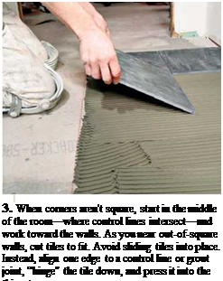
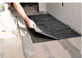
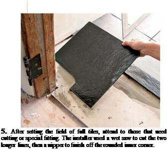
Подпись: 3. When corners aren't square, start in the middle of the room—where control lines intersect—and work toward the walls. As you near out-of-square walls, cut tiles to fit. Avoid sliding tiles into place. Instead, align one edge to a control line or grout joint, “hinge" the tile down, and press it into the thinset. image814Подпись: 5. After setting the field of full tiles, attend to those that need cutting or special fitting. The installer used a wet saw to cut the two longer lines, then a nipper to finish off the rounded inner corner. Подпись: PRO"ГIP Thinset adhesive should be moist enough to stick to the tile, but not so wet that it slides off a trowel. If thinset skins over while you're setting tile, recomb it with a notched trowel. But if it gets stiff in the pan or it doesn't stick readily to the tiles, discard it and mix a fresh batch. Likewise, if you move a tile after the adhesive has started to set, scrape the thinset off the back of the tile and the setting bed, and apply fresh mortar to both surfaces. llll

4. As tile fills each quadrant, have a straightedge nearby to see if tiles edges line up, especially if thinset has obscured the chalklines. Note: Chalklines indicate the middle of the tile joints. An experienced installer uses both the chalkline and a straightedge to align tiles—whichever gives the better-looking result.

sidewall, and made a second mark that repre­sented an extension of that middle tile joint. They lightly snapped a chalkline (as shown in photo 1) through the two marks to create a first control line. But they snapped the line lightly because they knew they might need to move it a bit before settling on its final location, as explained next.

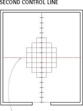
Before photo 2 was taken, the installers used a framing square to mark a second control line perpendicular the first, thus dividing the bath­room roughly into quadrants. They wanted full tiles against the threshold, so they placed one end of the story pole there and measured away from it to find a tile-joint mark close to the midpoint of the first control line.

The rest of such a layout is mostly fine-tuning, with an eye to the four time-tested tips of tiling, as outlined earlier: using full tiles at focal points, cutting as few tiles as possible, making layouts as symmetrical as possible, and avoiding tiles less than half size. For this, a story pole is essential.

SETTING THE TILES

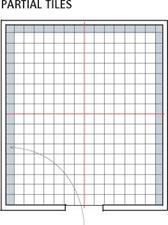
Set full tiles before partial tiles. To get a rhythm going, most tilesetters first set all the full tiles, and then attend to partial tiles, which take time to cut and set. However, you may want to make complex cuts beforehand, for example, where tiles meet obstacles in the middle of the field, such as a toilet closet flange. By cutting these tiles first, you can set them quickly and install other full tiles around them. Give the adhesive a day to harden, and you’re ready to grout the surface.

Note: This description is much condensed. If

you’re a perfectionist, you’ll fuss with the spacing between tiles or between tile sheets, and continue making little adjustments till the job is done.

Be sure to stand back from time to time for an overview of the layout.

Countertops

The front edge of a counter is almost always the focal point. Thus the primary control line runs parallel to the front of the counter, and all other layout lines are secondary to it. If the counter will be subject to moisture, install a membrane before installing a setting bed.

ESTIMATING TILE

If you’re installing a popular tile that a local sup­plier has in stock, wait till you’ve installed the set­ting bed before estimating tiles. If you order too many, most local suppliers will take back extras, as long as they aren’t damaged or returned too long after purchase. Ordering tiles is not compli­cated unless surfaces to be tiled have a lot of jogs, recesses, odd angles, and obstacles. Using a tape measure and a pad of graph paper, calculate the square footage of the surface to be tiled and add 8 percent to 10 percent for waste, damage, and future repairs.

Handmade or exotic tiles are another story.
Because they’re expensive and must be ordered

I Tiling a Floor_________________________________________

Tile layouts impose a grid that’s basically square in a room that often isn’t. Start by recording the room’s dimensions, use a framing square to see which corners are square, and note any obstacles to be tiled around.

FIRST CONTROL LINE

image806


Second Start tiling where Cut and install

control line control lines meet. partial tiles last.


image807image808

If the doorway is the focal center of the room, use a story pole to find the tile-joint mark closest to the middle of the doorway. Ideally, the first control line will run through that mark, and there will be full tiles along the threshold.

The second control line is perpendicular to the first, intersecting it roughly midway along its length. Although you can start setting tiles anywhere, it’s best to start where control lines meet in the highly visible middle of the room.

Place angle-cut and partial tiles away from the room’s focal center. Because cutting tiles takes longer than installing full tiles, most installers cut tiles after the field of full tiles is in place.

Подпись: PROnP Once you've established a room's two main (perpendicular) control lines, snap as many secondary layout lines as you like. Many tilesetters also snap lines around the perimeter of the room to indicate where cut tiles begin; they set all the full tiles within the lines first, then set cut tiles at the base of walls, cabinets, and fixtures. Подпись: 1111

well in advance, suppliers rarely accept returns. To save money, try to draw layouts that are accu­rate to an inch so you can count individual tiles. But you should still order extra tiles—say, 5 per­cent above your tile count—which is preferable to waiting 2 months for the next tile shipment from Italy. Besides, tile colors can vary greatly between batches. Your detailed drawings will also help you accurately frame out the area to be tiled.

Finally, when ordering tile, calculate the num­ber of trim pieces separately from your calcula­tions for field tiles. For each distinct piece of tile trim (such as surface cove, V-cap trim) add 15 percent to the lineal feet of trim indicated by the layout. Order at least two specialty trim pieces for any one-of-a-kind piece (such as radius-bullnose down angle). This is also the time to order compatible adhesives and color-matched grout and caulk.

TILE LAYOUT

Most tiles are square or rectangular. So the most common floor-layout dilemma is in imposing a grid that’s basically square onto a room that isn’t. Laying out walls and countertops is much the same, except that wall layouts are more affected by plumb. Wherever they occur, though, layout lines have the same purpose: They keep tile joints straight. When setting tile, it’s easy to obsess about individual tiles and spacers, getting lost in close-up details. Thus layout lines help you keep the big picture in view and so keep tile joints from straying.

FOUR TIME-TESTED TIPS OF TILING

Though the following rules make sense most of the time, bend them when you must.

Use full tiles at focal centers. A focal center is any area that the eye is drawn to: the front edge

I Tiles at the Sink


DON’T DO THIS! DO THIS!

image809

both sides


Symmetrical layouts look better. When a layout results in unequal tile widths along the sides of a kitchen sink—a very noticeable spot—either shift the layout or move the sink to create equal tile widths on both sides.


of a counter; a room’s entryway; or a center of activity such as a sink, large window, or hearth. Common sense says full tiles look better than cut tiles, so put full tiles in conspicuous areas. Con­versely, put cut tiles where they’ll be least noticed.

Cut as few tiles as possible. Cut tiles are extra work, and they don’t look as good as whole tiles. To avoid cutting tiles, you might be able to shift the layout a little to the right or left or slightly vary the width of tile joints.

Make layouts as symmetric as possible. This rule is both an extension and, occasionally, a contradiction of the two above. Imagine a kitchen-sink counter: The sink is certainly a focal center but may be smack dab in the middle of a tile field. There’s often no way to avoid cutting tiles around the perimeter of a sink. In that case, try to shift the layout (or the sink) so that you can cut tiles an even amount on both sides of the sink. The result will look much better than almost-full tiles on one side and narrow tiles on the other.

This is also a good rule for small counters, which you can see from side to side without turn­ing your head. If you must cut tiles, split the dif­ference at each end.

Don’t use tile pieces half size or smaller.

They’ll look terrible. It’s better to adjust the width of tile joints. Or shift the layout so that you have large cut tiles on both ends rather than a row of narrow ones on one end alone.


ESTIMATING TILE

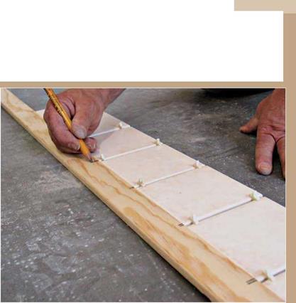
A story pole (also called a jury stick) is like an oversize yardstick but is divided into units that represent the average width of one tile plus one grout joint. Story poles give you a quick read on the number of full-size tiles you’ll need to get from point A to point B. For these homemade measuring devices, any straight board will do.


image810

FLOOR LAYOUT


MANAGING THE FRAMING START

Certain activities must take place before you begin framing. The dimensions and level of the foundation and slab need to be checked. If they are not perfectly level (which is not unusual), you must determine how far from correct they are, whether they are within tolerances, and what types of adjustments you must make. It is important that the dimensions are accurate, and the building is square before you start. Note, too, that the cabinets, floor covering, drywall, roof trusses or rafters, and much more depend on the measurements being accurate and square.

The four steps to getting started, covered in this chapter, are:

1. Checking the exterior wall dimensions

2. Checking the reference lines for square

3. Adjusting the reference lines to correct dimensions and square

4. Checking the building for level

Checking Exterior Wall Dimensions

If you have the concrete-work reference points handy, getting started will be easier for you. If you don’t, establish reference lines of your own. Be sure to mark these lines well, since you will be using them throughout the job. Using clear marking paint in inverted cans makes it easy to protect your lines on the concrete.

You will want to use the reference lines to find any deviations from plan measurements or any out-of­square parts of the foundation. Start by stringing dry lines that will allow you to measure. The more of the building you can measure from these lines,

the more likely you are to find any mistakes. Look at the plans, and string two dry lines perpendicular to each other and covering as long a distance of the building as possible. If you can add two more dry lines, one on each side and opposite to the first two, that will help. (See the “Start-Up" example.) Once you have established your lines, take measurements between the lines and to the major exterior walls in the building. Make a quick footprint of your building, and as you measure the distances, write them down on the footprint. (See “Footprint Sketch Dimensions" example later in this chapter.)

A laser can also be used to establish square lines.

The laser will give you dots that you just need to connect. Set the laser up at a convenient position so you will be able to chalk reference lines. Once you have established the lines, use your tape and a 3-4-5 triangle to check for accuracy.

Laser Dots. Note: a fifth laser dot would be visible under the back of the laser.

Loring

The Loring is the same as the Bodega except that, in this case,

I have added a small bump-out in the loft. Once again, the loft is not counted in the square footage listed but contains ample space. A downstairs bedroom is also aval – able.

Square feet: 681

With add-on: 774 House width: 16’

House length: 30’

Porch: 6’ x 15%’

Great Room: 9%’ x 15’ Kitchen: ІУ2 x 9%’

Bathroom: 5%’хб’

Half Bath: 41/2’ x 5’

Addition: 7’x12’

Ceiling height: 7’ 6” – sizes are approximate

Fasten according to code

Hold screws or nails back about 5/s in. from the edges of the panel, and drive them in straight so you don’t break the paper. Follow the fastening schedule for drywall that applies in your area. When ceiling joists are 24 in. o. c., nails or screws are usually driven every 8 in. along the edge of the panel and every 12 in. in the middle.

Some builders use drywall panel adhesive when attaching sheets of drywall. The adhesive is applied with a caulking gun, just like caulk or sealant. With panel adhesive, the need for screws
or nails is greatly reduced. Don’t use adhesive over a poly vapor barrier or kraft paper-faced insulation; it’s designed to affix drywall to a wood surface. Follow the application and instal­lation instructions on the label.

Corner details

If you provided backing or deadwood while building interior walls (see Chapter 4) and installing roof trusses (see Chapter 5), you’ll be able to drive nails or screws along the walls to fasten drywall panels. But if solid backing mate­rial for drywall was not nailed to the tops of parallel walls or in the corners where walls in­tersect, metal drywall clips can be used instead. See the illustration on p. 223 for instructions on using these clips. Unlike a drywall corner secured with nails or screws, a corner secured with clips can be more resistant to cracking when the framing material moves in response to temperature fluctuations.

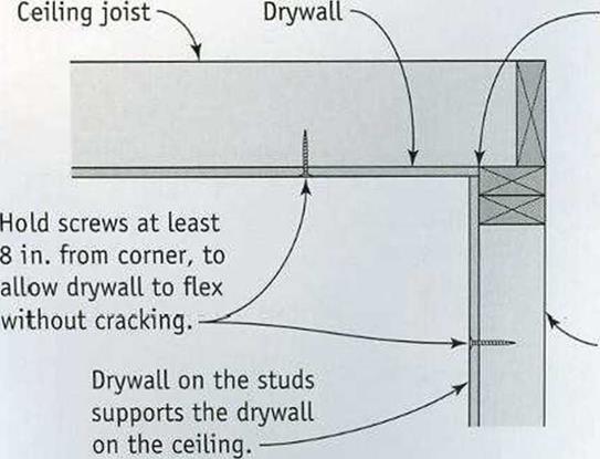
Подпись:Another strategy is to let the corner “float,” eliminating nails where a ceiling panel meets the wall. The top edges of wall panels are

Подпись:

Подпись: Cutting drywall isn't difficult, once you learn how to score through the paper covering with a utility knife. The panels have a gypsum core that makes them heavy and delicate.They create a lot of dust, too, especially when making cuts with a saw. Fasten according to code

then pushed snugly against the ceiling panels, holding them in place (see the top illustration on p. 224). Again, this can help prevent corner cracks at the ceiling-wall juncture due to wood shrinkage or truss uplift. If you’re uncertain about how to handle drywall corners, check with experienced builders in your area.

Once all the ceiling panels are in place, run a bead of caulk where the ceiling panels butt the exterior walls to reduce air infiltration (see the top illustration on p. 224). I finish the ceil­ing by marking the location of wall studs with a small pencil mark on the ceiling drywall. These marks help when nailing drywall to the walls. Don’t use a keel on drywall (unless it is covered with drywall tape) because it can bleed through paint.

STEP 3 INSTALL THE WALL PANELS

Hanging drywall on the walls is easier than hanging it on the ceiling. You have to work around window and door openings, and there are more electrical outlet openings to mark and cut, but you don’t have to work overhead. It’s important to know that some electrical wires (for the thermostat, doorbell, range hood, and so on) will not be enclosed in a box. Electricians often wrap those wires around a nail to locate their position. All you need to do is make a small hole in the drywall and pull the wires through.

Plan panel installation

It’s smart to plan an installation sequence when there are a number of walls to finish with

Подпись: USING DRYWALL CLIPS TO SECURE THE ENDS OF DRYWALL SHEETS Fasten according to codeFasten according to codeПодпись: Drywall clips eliminate the need for backing at intersecting walls and on cap plates.drywall. Determining which walls to cover first, and how panel layout will work, saves time and aggravation. Here are some tips to help you plan the installation sequence for walls:
HANG PANELS HORIZONTALLY. By installing 12-ft. panels horizontally, you greatly reduce the number of joints in a wall. The top panels should be hung first. Don’t worry if the bottom panel doesn’t extend all the way to the subfloor; this small gap will be covered by the baseboard trim. For rooms with 9-ft.-high walls, use 54-in.-wide drywall panels instead of the standard 48-in.-wide panels.

START ON CLOSETS FIRST. Check to see whether there are any closets that must be drywalled before working on long walls. Sometimes it’s easier to get large drywall pieces into a closet through a wall rather than through the closet door. Don’t bother cutting and installing small pieces of drywall to completely cover a closet. You can do that later with scrap pieces cut from the long sheets. At this stage, you just want to have an easier time getting big pieces into the closets.

WORK FROM THE OUTSIDE IN. I like to drywall exterior walls before interior walls. Leaving the interior wall framing open when you start gives you greater freedom to maneuver the panels. To maximize this freedom, drywall the interior hallways last.

PAY ATTENTION TO BACKING AT WALL INTERSECTIONS. As shown in the bottom right illustration on p. 224, backing can sometimes determine which wall should be covered with drywall first. When 2 x6s have been used for backing where 2×4 walls intersect, there will be only a l-in.-wide nailing surface for attaching drywall. In this situation, always install the intersecting wall’s drywall after the other wall has been covered. Butt the intersecting wall’s panel tightly against the adjoining wall panel to make a solid corner.

Install the panels

As mentioned earlier, the top panels should be installed first. It’s important to butt the top edge

of each wall panel snugly against the ceiling drywall. To make installation easier, you can start a few nails near the top of a sheet before you raise the panel into position.

Although I drive a few nails just to hold a panel in place, I like to use screws in the rest of the sheet on both ceilings and walls. Screws hold better, resist popping when framing lum­ber shrinks, and can be installed quickly once you get into the rhythm of using a screw gun.

Подпись: On exterior walls, prevent air infiltration with a bead of caulk at the corner before installing the drywall.Подпись:Fasten according to codeПодпись:Подпись:Подпись:

If you use nails in the middle of a panel, code may require that the panels be double-nailed (see the illustration on the facing page).

When fastening a panel, work from the center to the outside edges. If you do use nails, drive the first set, then go back later and drive the second set, making sure the drywall is tight against the wall framing. When driving nails, it’s always advisable to push the panel tightly against the wall.

When hanging the bottom row of drywall,
stagger the end or butt joints, just as you did on the ceiling. The bottom panels can be placed against the wall, then raised and held in place against the top sheet with a drywall lifter, al­lowing you to concentrate on fastening the sheet (see the sidebar on the facing page). Long sheets can be raised with a drywall lifter at each end.

Try to keep butt joints away from the center of the wall so that the joints will be less obvious. Also, have a sheet break over a door or window rather than right at the edge of a king stud or trimmer. A joint at the edge of a door or window increases the likelihood of a crack in the drywall as the wood dries. Run panels all the way across doors and windows when you can, then cut them out later with a saw or router. You can also run a panel past an outside corner, then cut it flush with a utility knife after the panel has been fastened in place. This eliminates the need to measure and mark the panel.

PROPER DRYWALL INSTALLATION
ON 2×4 INTERSECTING WALLS
USING 2×6 BACKING

Fasten according to code

1/2 in.

1 in.

2×6

backing

WRONG

You’ll only have a 1/2-in.-wide nailing surface if you install drywall on the intersecting wall first.

Intersecting wall

Test Results

A comparison of macrotexture depths of courses executed with various asphalt mix­tures has been presented in an Australian paper (Oliver, 2001):

• Surface dressing (greater than 10 mm)—macrotexture less than 1.5 mm

• AC (greater than 10 mm)—macrotexture 0.4 to 0.8 mm

• Porous asphalt—macrotexture less than 1.2 mm

• SMA—macrotexture less than 0.7 mm

• Slurry seal—macrotexture 0.4-0.8 mm

• Cement concrete (brushed)—macrotexture 0.2-0.7 mm

Changes in some SMA characteristics occurring over time have been indicated in various investigations. In the United Kingdom, Richardson (1997) described changes in the SMA macrotexture during the months following the construction of a course. The SMA macrotexture, just after placement, was initially at a level of 1.5-1.6 mm. Then it gradually reduced to 1.1 mm after 21 months. It should be added that the reported results applied to an SMA with a gradation that was used in the United Kingdom to achieve a required high macrotexture after placement (see Chapter 10). The applied gradation was characterized by a gradation curve below the typical gra­dation limits according to German guidelines (see comparison of curves in Chapter 14, Figures 14.2 through 14.5).

It should be noted that gritting used to enhance SMA antiskidding properties has additional consequences, especially in the first period after execution, namely a slight decrease in the surface macrotexture. Grit particles (and the remains of them crushed by rollers) gather in spaces among SMA coarse aggregates and only some time after the opening of a road to traffic are they pulled up (sucked out) by vehicle tires and scattered across the shoulder or median (Richardson, 1997). So just after gritting, macrotexture may be low (see Figure 12.6b), it but will eventually improve.

Argentinean investigations (Bolzan, 2002) conducted just after a highway modern­ization project, including the placement of a new SMA 0/19 course, showed it provided high macrotexture 2.2 mm deep (measured by the sand patch method). At another section of SMA 0/12 mm, the macrotexture depth amounted to only 1.4-1.7 mm.

In Germany Behle et al. (2005) conducted research into the relationship between PSV and final skid-resistance of an SMA layer. The authors presented the results of measurements with a sideways coefficient routine investigation machine (SCRIM) over a period of 4.5 years and a concept for calculating the PSV of mixed aggregates with different individual PSVs by weighted average.

By and large, based on straightforward experiments and a series of results, the following general technological recommendations to improve the antiskidding prop­erties of SMA wearing courses may be put forward:

• Apply mixtures with a lower maximum aggregate size (more contact points between the SMA and tire).

• Consider microtexture—prefer aggregates with a high PSV index (low pol­ishing susceptibility) and aggregate mixtures of various rocks with various wear rates; if possible, also use artificial aggregates (slags).

• Consider macrotexture—avoid factors that increase the risk of squeez­ing mastic out on a surface such as mixtures with an insufficient con­tent of voids and or those susceptible to compaction under traffic; for the same reason do not use pneumatic rollers and use vibratory rolling with caution.

• Apply grit to make the surface rough by spreading the grit evenly, followed by rolling while the surface is hot enough.

• Open the lane to traffic only after the SMA has finally cooled off.