ANTIsKID properties

Antiskid features of wearing courses of asphalt surfacing are described in terms of the friction coefficient, which depends on the micro-texture of the aggregate and the macro-texture of the placed mixture (Gardziejczyk and Wasilewska, 2003). As this property is very important, the range of available publications on the topic at issue is quite broad (Gardziejczyk, 2002; German DAV Report, 2001; Huschek, 2004; Jordens et al., 1999).

Different pavement qualities, in relation to the speed of vehicles, have a deci­sive impact on antiskid properties (Hunter, 1994). At low speeds, polishing resis­tance has a decisive impact, hence the durable microtexture of the aggregate surfaces is significant; in this instance the polished stone value (PSV) can be used as a selective index for evaluating an aggregate’s resistance to polishing. At high speeds, the macrotexture depth of the wearing course has a decisive impact; the presence of small channels around aggregate particles on the surface enables water discharge, preventing the formation of a hydroplaning effect (skid­ding layer).

The SMA macrotexture depth depends on the maximum aggregate size in the mixture and the design of the mix (e. g., the level of filling voids among coarse aggre­gates on the surface of a course with mastic); see Figure 12.6.

(a) (b)

image151

FIGURE 12.6 SMA macrotexture before opening to traffic: (a) nongritted and (b) gritted. (Photo courtesy of Krzysztof Blazejowski.)

ANALYTICAL APPROACH TO LIGHTING WARRANTS [3]

An analytical approach to determining if roadway lighting is warranted was developed through the National Cooperative Highway Research Program (NCHRP Report 152) using four comprehensive evaluation forms. The four forms relate to non-controlled – access roadways, intersections, freeways, and interchanges, and are presented in Figs. 7.61, 7.62, 7.63, and 7.64, respectively [10]. The forms are used by multiplying the rating of a characteristic by the difference in its unlighted and lighted weight to obtain a quantitative measure of the effect of that characteristic on driver visual infor­mation needs. After all the characteristics are rated, the scores are summed to obtain an overall measure of driver information needs.

There is an established “minimum warranting condition” of a given number of points for each of the four forms. The exact number of points is determined by assum­ing a rating of 3 for each of the characteristics. It should be emphasized that the mini­mum warranting condition is not firm, but merely a starting point. This method is flexible and permits modifications to fit local needs. This procedure also provides a method for administrators or planners to prioritize lighting projects by using objective standards to determine where lighting would be most beneficial.

NEW VESICA

The New Vesica is essentally the Bodega turned sideways. The New Vesica is officially 278 square feet, but, if the loft were included, it would measure in at just over 450 square feet.

Square feet: 261

With add-on: 356 House width: 14’ House length: 24’ Porch: 6’ x 13%’

Great Room: 9’ x 13%’ Kitchen: 73/V x 8’

Bathroom: 7%’x5’

Addition: 7’ x 93%’

Ceiling height: 7’ 6”

Loft height: 7’

-sizes are approximate

Warrants for Tunnel Lighting

The use of artificial daytime lighting is warranted when user visibility requirements are not satisfied by the natural sunlight. Overall tunnel visibility varies considerably with such factors as geometry of the tunnel and its approaches, traffic characteristics, roadway and environmental reflective surfaces, the climate and orientation of the tunnel, and visibility objectives. Comprehensive literature is available on the technical aspects of visibility and lighting of tunnels [9]. Information on lighting levels for tunnels requires a detailed analysis of the tunnel approach characteristics. Tunnel lighting requires considerable experience to achieve proper design.

7.19 ROADWAY REST AREAS [9]

• Parking areas. The recommended average maintained lighting level is 1.0 fc (11 lx) for both automobile and truck parking areas with a uniformity of 3:1 to 4:1 over the entire area. Special areas that should have the higher levels are handicap ramps, sanitary disposal stations, and other features that require detail viewing.

• Activity areas. The major pedestrian activity areas are restrooms, information cen­ters, and walkways to and from the buildings and the parking lot. Minor activity areas include picnic tables, dog walks, and other walk areas. The recommended lighting level for major areas is 1.0 fc (11 lx) with a 3:1 to 4:1 uniformity ratio. Minor activity areas should be lighted to 0.5 fc (5 lx) with a uniformity ratio of 6:1 [3].

Rest areas are often located in remote areas that are not readily accessible by bucket trucks or other special maintenance equipment. This requires that lighting system components be selected that provide maximum protection against vandalism and require minimal maintenance. One device that has been used to allow pole-mounted luminaires to be maintained, and lamps changed, without using a bucket truck is an individual lowering device (ILD) which allows the pole-mounted luminaires to be lowered to ground level, one at a time, for servicing. This is done with a hand-operated winch that is lightweight and easily portable by one person. One such ILD (Fig. 7.60) that has been designed to DOT requirements and used successfully is manufactured by ITS Products Inc., Dothan, Ala.

FIGURE 7.60 Lowering device manufactured by ITS Products Inc.

Example of Modelling of the Resilient Behaviour of Pavements

To model the resilient behaviour of pavements, the French pavement laboratory, LCPC, has developed a finite element program called CVCR, which is a part of the finite element code CESAR-LCPC (Heck et al., 1998; Heck, 2001a, b). This program allows the modelling of the response of pavements in 3D, under moving wheel loads, and incorporates the following material models:

• Linear elasticity

• The Huet-Sayegh visco-elastic model for bituminous materials.

• Two non-linear elastic models for unbound granular materials: the Boyce model, modified to take into account anisotropy (Hornych et al., 1998) and the well known k-0 model (Hicks & Monismith, 1971). These models have been de­scribed in Chapter 9, Section 9.4.1.

The example below (Hornych et al., 2002) presents an application of CVCR to the modelling of a low traffic pavement with a granular base, tested on the LCPC pave­ment test track. In this study, the objective was, in particular, to evaluate the ability of the model to simulate experimental pavement response for different load levels and different water contents of the unbound granular material.

Organizing the Job Site

After the plan review, you need to organize the job site. Figure out what your initial manpower needs and schedule are, and what tools you’ll need for the job. The first day on the job site is usually a challenge.

1. Manpower needs. Typically, on the first day, your crew is ready to go to work and will be looking to you for instruction. At the same time you may not be sure if the concrete

is level or the right size. Meanwhile, the superintendent may be on his way over with his list of things you need to take care of. If you have too many framers, everyone might be standing around until you get the job organized. If your schedule allows, start with just a two-man crew to check the foundation or slab for level and size and to get some lines chalked and some detailing done.

2. Manpower tasks. Knowing which jobs you want each framer to do before you get there always helps. Also, keep a couple of back-up tasks (such as cleaning out the truck or fixing tools) in mind in case something prevents you from starting right away. First-day jobs might include:

• Cleaning the slab or foundation

• Checking concrete dimensions

• Checking level of concrete

• Cutting makeup and headers

• Nailing makeup and headers

• Chalking lines

• Setting up chop saw (radial arm or similar)

• Building plan shack

• Detailing plates

3. Tools. Not having the right tools can be like trying to cut the Thanksgiving turkey with a table knife. The tool list that follows will help you determine what you need. For example, you can look at the plans to find out what size bolts are being used so you can be sure to have the appropriate drill bits and impact sockets ready.

It’s easy to show up the first day without some of the necessary tools. Also, you might use different tools at the beginning of a job and at the end of a job. Highlighting the tools you need on the Tool List before the job starts will help you prepare and save time.

Note that the “Location" column on the Tool List at the end of this section refers to the location where the tools are kept. (See legend on tool list.) The locations listed can be adjusted to your own situation.

4. Plans. Any time you can devote to the plans before you start the job is probably well spent. Two things are particularly important for getting started. First, decide where you are going to pull your layout from (see Chapter 7), and second, decide which lines you are going to set for reference (see “Getting Started" in Chapter 13).

Looking at plans on the job site can be like trying to read a map while on a motorcycle: there is always the sunshine, wind, or rain.

On the job site, you’ll be juggling a number of things. Your crew will be asking you what to do next, and you’ll have to think about the material you need and if you have enough nails, for example. It will take you about an hour to absorb as much information from the plans on the job site as you can in fifteen minutes off the job site. A good habit is to review the plans for ten minutes every morning away from the job site. You’d be surprised at how many mistakes are avoided by doing this.

Tool List

Tool

Location

Quantity

Broom

T

1 per crew

Chalk bottle

T

1 per crew

Knife blades case

H

1 per crew

Vice grip

MB

1 per crew

5" crescent wrench

MB

1 per crew

8" crescent wrench

MB

1 per crew

Allen wrench set

MB

1 per crew

Screwdriver

Standard

SR

2 per crew

Phillips

SR

2 per crew

PLUS

Retractable safety line

JH

2 per crew

Lanyards

JH

4 per crew

Regulators

FB

V2 per gun

Compressor oil

TB

1 per crew

Gun oil

TB

1 per crew

Plumb bob

FB

1 per crew

Electric three-way

FB

2 per crew

Air three-way

FB

2 per crew

Saw guides

FB

1 per crew

Screwdrivers

FB

Misc.

Chain saw

SB

1 per crew

Chain saw blades

FB

1 per crew

Palm nailer

LB

1 per crew

Ear plugs

FB

Misc.

Back support

JH

Misc.

5. Schedule. Developing a schedule is a difficult task, and one that should be a responsibility of the contractor. If, however, the framing contractor does not provide one, the lead framer should create his own. It is a valuable tool that will help you organize the job and then analyze how the work is going.

6. Plan shack. On bigger jobs, a plan shack is a good tool to have. It doesn’t have to be fancy, but if it keeps your plans dry and helps keep the job organized, it is worth the time and material.

Plan shack

Conclusion

Your time spent preparing for a job sets the tone for managing the whole job. It lets you hit the job running and puts everyone on notice that you are serious about making this job run smoothly.

With a picture of the plans in your head, a job site check list complete and your tools organized you will start out answering questions and taking control of what needs to be done to get your project framed.

FIGURING THE WEIGHT OF A PIPE

Figuring the weight of a pipe and its contents is necessary when you are choosing the needed strength of a pipe hanger. There is a formula that you can use to accomplish this goal. Let’s say that you want to know how much a

Nominal pipe size (NPS), in IP

ASHRAE std. wt. size, mm

AWWA pipe size, mm

NFPA pipe size, mm

ASTM copper tube size, mm

Nominal

pipe

size DN, mm

Vs

_

в

6

3/ie

8

8

У4

8

10

10

%

10

12

12

y2

15

12.7 & 13

12

15

15

%

18

18

3/4

20

22

20

1

25

25

25 & 25.4

28

25

Г/4

32

33

35

32

1У2

40

45

38 & 38.1

42

40

2

50

50 & 50.8

51

54

50

2Уг

65

63 & 63.5

63.5 & 64

67

65

3

80

75

76 & 80

79

80

ЗУ2

89

90

4

100

100

102

105

100

4У2

114.3

115

5

127

130

125

6

150

150

152

156

150

8

200

200

203

206

200

10

250

250

257

250

12

300

300

305

308

300

14

350

350

18

400

400

18

450

20

500

500

24

600

600

28

700

30

750

32

800

36

900

40

1000

44

1100

48

1200

52

1300

56

1400

60

1500

FIGURE 11.2 ■ Equivalent metric (SI) pipe sizes. (Courtesy of McGraw-Hill)

piece of pipe weighs. You will need some information, which can be found in Figure 11.5. And, you will need the formula, which is as follows:

W = F X 10.68 X T X (O. D. – T)

You’re probably wondering what all the letters mean, and you should be. I’ll tell you. The letter W is the weight of the pipe in pounds per foot. A relative

Nominal rod diameter, in

Root area of thread, in2

Maximum safe load at rod temperature of 650°F, lb

Vi

0.027

240

s/ie

0.046

410

%

0.068

610

Vi

0.126

1,130

%

0.202

1,810

3/4

0.302

2,710

%

0.419

3,770

1

0.552

4,960

lVs

0.693

6,230

lVi

0.889

8,000

1%

1.053

9,470

IVi

1.293

11,630

1%

1.515

13,630

13A

1.744

15,690

1%

2.048

18,430

2

2.292

20,690

2У«

3.021

27,200

2 Vi

3.716

33,500

2%

4.619

41,600

3

5.621

50,600

3Vi

6.720

60,500

ЗУ2

7.918

71,260

FIGURE 11.3 ■ Load ratings of threaded rods. (Courtesy of McGraw-Hill)

Pipe size, in

Rod size, in

2 and smaller

3/8

2Vi to 3Vi

Vi

4 and 5

5/«

6

3/4

8 to 12

%

14 and 16

1

18

lVfe

20

Г/4

24

IVi

FIGURE 11.4 ■ Recommended rod sizes for individual pipes. (Courtesy of McGraw-Hill)

weight factor, which can be found in Figure 11.5, is represented by the letter F. Wall thickness of a pipe is known as the letter T. You have probably guessed that O. D. represents the outside diameter of the pipe, in inches. I said that you could figure out the weight of pipe and its contents. To determine the weight of water in pipe, refer to Figure 11.6.

FIGURING THE WEIGHT OF A PIPE
Подпись: been there done that As a young plumber, I guessed at a lot of math re-quirements. This was not always smart. Don’t gamble when it comes to pipe support. Refer to the tables here to make sure that your choice of hangers is safe and secure.

FIGURE 11.5 ■ Relative weight factors for metal pipe. (Courtesy of McGraw-Hill)

IPS, in

Weight per foot, lb

Length in feet containing 1 ft3 of water

Gallons in 1 linear ft

‘/4

0.42

0.005

%

0.57

754

0.0099

l/2

0.85

473

0.016

%

1.13

270

0.027

1

1.67

166

0.05

ІУ4

2.27

96

0.07

P/2

2.71

70

0.1

2

3.65

42

0.17

2У2

5.8

30

0.24

3

7.5

20

0.38

4

10.8

11

0.66

5

14.6

7

1.03

6

19.0

5

1.5

8

25.5

3

2.6

10

40.5

1.8

4.1

12

53.5

1.2

5.9

FIGURE 11.6 ■ Weight of steel pipe and contained water. (Courtesy of McGraw-Hill)

Numerical Simulation of Pavements Behaviour from Accelerated Tests

Erlingsson (2007) describes two thin pavement structures that were tested in ac­celerated testing by using a Heavy Vehicle Simulator. Both were surface dressed structures, one with 20 cm thick unbound base course layer and the other with the base course divided into a 10 cm bitumen stabilized base over 10 cm unbound base. Both structures were instrumented to estimate deflections, strains and stresses in various locations inside the structure. A numerical analysis was also carried out to simulate the response behaviour of the structure that could be compared with the actual measurements. The simulation was performed using different techniques: 3D and 2D axi-symmetric analyses, finite element and multi layer elastic theory, linear elastic and non-linear elastic base behaviour. The results were further used to model the permanent deformation development in each layer. A cross section of the two structures is shown in Fig. 11.8.

Figure 11.9 shows the induced vertical stress under the centre of a single tyre load for both structures where the axle load is 120 kN, or close to one conventional axle load (11.5 ton in the EU), and the tyre pressures is 800 kPa.

Fig. 11.8 Two test pavement structures: (a) IS02 is an unbound structure and (b) IS03 is a bitumen stabilized structure

Note: The instrumentation used for the response measurements is shown as well.

40

50

0

Fig. 11.9 Comparison of measured and calculated vertical induced stresses under the centre of a single tyre as a function of depth for both pavement structures IS02 and IS03 Note: (a) structure IS02 is the unbound structure; (b) structure IS03 is a bitumen stabilized struc­ture. The numerical simulation is carried out using different techniques where 3D = three dimen­sional analysis, 2D Axi = two dimensional axi-symmetric analysis, FE = finite element, MLET = multi layer elastic theory, LE = elastic behaviour and NLE = non-linear elastic base behaviour.

One can see in Fig. 11.9a the importance of taking into account the non-linear base behaviour for the unbound structure IS02. The linear analyses overestimate the stresses in the upper part of the structure, compared with the two non-linear analyses. In the structure with the bitumen-stabilized base, Fig. 11.9b, this is not as prevalent and both the linear as well as the non-liner analyses capture the overall response of the structure quite reasonably.

Finally Fig. 11.10 shows the results of the predicted as well as the measured accumulated permanent deformation for the base, sub-base and the subgrade layer as a function of load repetition for both pavement structures. The response over the first 300 000 load repetitions are shown.

A simple power law assumption was used in calculating the permanent deforma­tion. This seems to give a satisfactory agreement between the numerical simulations and the measurements for both structures. The largest deviation took place during the early part of the test but, thereafter, the rate of increased permanent deformation was quite similar between the analyses and the actual measurements.

It is also interesting to compare the measured and calculated permanent defor­mation of the two structures. Adding the three curves of Fig. 11.10 together gives the total permanent deformation, i. e. rutting, in the unbound part of the structure.

Number of passes, N Number of passes, N

Fig. 11.10 Prediction versus measurements of permanent deformation development for the three unbound layers as a function of load repetition for both pavement structures IS02 and IS03

The one with the upper part of the base stabilized with bitumen shows a total of about 14 mm of deformation after ca. 300 000 passes, but the other with un­bound base shows almost a 40 mm deformation after the same number of passes. This indicates quite a different “lifetime” of the two structures. This difference in “lifetime” does not prevail in the measurement and calculation of vertical stresses, where stresses at the top of the subgrade are almost the same for both structures (see Fig. 11.9).

TUNNEL LIGHTING

A tunnel is defined as a structure over a roadway that restricts the normal daytime illumi­nation of a roadway section so that the driver’s visibility is substantially diminished. Design of tunnel lighting requires adaptation for driver needs in the approach, and the

FIGURE 7.59 Lighting adaptation zones for tunnel lighting. Approach: The external roadway area leading to the tunnel. Portal: The plane of entrance into the tunnel. Threshold zone: The area inside the tunnel where a transition is made from the high natural lighting level to the beginning of the transition zone. Transition zone(s): Areas that allow the motorist to achieve appropriate eye adaptation by incre­mentally reducing the level of luminance required in the threshold zone to the luminance of the interior zone. Interior zone: Area within the tunnel after eye adaptation has been completed.

threshold, transition, and interior zones, as presented in Fig. 7.59. Tunnels are classified by structure length and geometric alignment (visibility through the structure). A straight tunnel having an overall length from portal to portal equal to or less than the safe stopping sight distance (SSSD; Table 7.18) is considered to be a short tunnel. A tunnel with an overall length greater than one SSSD, or having an alignment or curvature that prevents motorists from seeing through the structure to the exit end, is considered to be a long tunnel. Overpasses and underpasses are those structures in which the length does not exceed one width of the roadway over (or under) which they are constructed.

Underpasses with a length-to-height ratio of approximately 10:1 or less will not nor­mally require daytime lighting. When the length-to-height ratio exceeds 10:1, it is neces­sary to analyze the specific conditions, including vehicular and pedestrian activity, to determine the need for daytime lighting. Roadways that are not continuously lighted warrant underpass lighting in areas having frequent nighttime pedestrian traffic or where

TABLE 7.18 Safe Stopping Sight Distances

Traffic speed

Minimum safe stopping sight distance (SSSD)[8]

km/h

mi/h

m

ft

50

30

65

200

60

40

85

250

80

50

130

360

90

55

160

425

100

60

185

495

110

65

220

570

*Assumes average prevailing speeds in a straight and level tunnel approach roadway are at, or near, the posted speed limit of the facility. For other geometric conditions, refer to the AASHTO documents.

Source: A Policy on Geometric Design of Highways

and Streets, American Association of State Highway and Transportation Officials, Washington, D. C., 2004, with permission.

unusual or critical roadway geometry occurs under or adjacent to the underpass area. On roadways with continuous lighting, favorable positioning of luminaires adjacent to the underpass can often provide adequate lighting without supplemental luminaires. Lighting levels and uniformities should match the values on the adjacent roadway when practical. Because of limited mounting height, when lights are placed within a tunnel, special consideration should be given to glare and uniformity. Raised lighting levels may be achieved by using closely spaced low-wattage luminaires. Such increased levels should not exceed twice that of the adjacent roadway.

ODD OR PROBLEMATIC SETTING BEDS

The beds described next may require special techniques and materials.

Plastic laminate countertops are acceptable setting beds if they’re solidly attached. Scuff the surface with 80-grit sandpaper, wipe with a rag dampened with solvent to remove grit and grease, and fill any voids. Then use an epoxy­based thinset to bond the tiles. Alternatively, you can cover the old laminate with!4-in. backer board, adhering it with an application of epoxy thinset, and 1-in. corrosion-resistant screws spaced every 6 in. around the perimeter of the countertop and every 8 in. in the field. Sink screw heads flush, vacuum the backer board, and then use latex or epoxy thinset adhesive to bond tiles. Note: The recommended 1-inch screw assumes the combined thickness of the countertop materi­als is at least 1 ‘/ in.

Tiling over existing tile is a reasonable alterna­tive to ripping it out, as long as the old tile isn’t cracked and is well adhered and the substrate is solid. Scuff the tile with a carbide-grit sandpaper. Vacuum the surface well, and wipe with a damp rag. Because tile surfaces are not perfectly regu­lar and grout joints are recessed, first use a flat trowel to spread a layer of epoxy thinset to build up grout joints and level the surface. Wait a day. Then use a notched trowel to apply a setting bed of epoxy thinset.

Two caveats: Because of the risk of leaks, don’t tile over tiled shower-stall floors. Rather, tear out the old floor, replace the shower-pan membrane, and tile atop a newly floated mortar bed. Second,

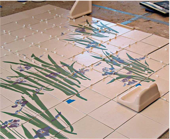
image805 Подпись: To avoid cutting handmade tiles on the tub sidewall, the installer laid out tiles on the floor, using plastic spacers to simulate grout joints. She then floated the walls to the exact dimensions of the tile assembly. (Vacuum floors well before laying tile on them because dust can compromise a setting bond.)

don’t install tiles 2-in.-sq. or smaller over existing tile because they will telegraph the old surface’s irregularities. Instead, use large tiles.

Resilient flooring is acceptable if there’s a sin­gle, uncushioned layer that’s well adhered to a stable subfloor. Cushioned or multilayered floor­ing will flex too much to be a stable base for tile so, to be sure, use a utility knife with a hooked blade to cut out a cross-section of flooring in an inconspicuous spot.

Painted walls are okay as long as the paint is well attached and the wall doesn’t flex. Drill a small exploratory hole to determine the composi­tion and thickness of the wall. If it’s drywall less than 58 in. thick, install a layer of 54-in. or 58-in. drywall over it. If the wall is traditional plaster (hard to drill through), it’s probably fine. Prep painted walls by sanding them with 100-grit sandpaper, and wipe with a damp rag. Use a latex thinset adhesive.

Other situations.

► Papered walls? Strip ’em! Vinyl wall coverings are supposedly tenacious enough to support tile, but it’s risky.

► Veneer paneling? Not recommended. Typically 54-in.- to 58-in.-thick, it will flex, cracking grout joints, and eventually dislodging tiles.

Tile Estimation and Layout

At this point we’ll assume that the substructure is sturdy and stable and the setting bed is in place. Careful layout is the key to a good-looking job, so don’t begrudge the time it takes. The right layout will align tile joints correctly, create a pleasant symmetry, allow you to cut tiles to size before­hand and—most important—enable you to set tile accurately and quickly while the clock is tick­ing for that fast-drying adhesive.