MAKING A HOUSE BEAUTIFUL

MAKING A HOUSE BEAUTIFUL

Interior Trim, Cabinets, Countertops, and Closets

When I’m feeling nostalgic, I think about the fancy, well-crafted toolkit I carried from job to job before I switched to a 5-gal. plastic bucket. That kit had a place for all my finish tools—handsaws, levels, small hammers, razor – sharp chisels with their blades wrapped in soft cotton, and planes that left long curls of wood with each pass. My brother, Jim, still has his shiny, metal miter box with its long backsaw—that’s what we used to make perfect cuts in trim before chopsaws came along. Back in the late 1940s and early 1950s, those were the tools that master builders passed down to us “kids” as they taught us the craft.

Today, carpentry is different. Power tools dominate—from motorized miter saws (chopsaws) and pneumatic nailers to cordless drills, belt sanders, random – orbit sanders, and jigsaws. And many of the things we used to build at the job site, such as kitchen cabinets, bathroom vanities, and door and window jambs, are now factory-made products that arrive ready to install. Despite these changes, basic hand-tool and careful layout skills are still essential, especially at this stage of the game, when the rough frame of the house, with all its imperfections, has been covered by drywall and the walls have been painted. Now it’s time to prepare floors for vinyl and carpet; install interior doors, window casing, and interior trim; and secure cabinets and countertops. Do this work right, and the inside of your house will begin to look beautiful and much more livable.

STEP 1 INSTALL UNDERLAYMENT FOR VINYL FLOORING

Because vinyl flooring is quite thin, it is common to install sheets of underlay – ment over a subfloor to provide a smooth, level base for the vinyl. Typically just

Add character with salvaged doors. A new house gains some wonderful history when it has a few old doors. Interesting, beauti­fully made old doors can be found at architec­tural salvage yards and building-supply recyclers and at Habitat Re-stores (see Resources on p. 279).


и їм їм їм и їм їм їм їм їм їм їм їм їм їм їм їм їм їм и їм їм їм їм їм їм їм їм їм їм їм їм їм и їм їм їм їм їм їм їм їм їм їм їм їм їм їм и їм їм їм їм їм їм їм їм їм їм їм їм їм и їм їм їм їм їм їм їм їм і

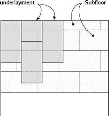
INSTALLING UNDERLAYMENT FOR A VINYL FLOOR


4-ft. by 8-ft. sheets of

MAKING A HOUSE BEAUTIFUL


4 in.


£4 in.


Stapling or nailing pattern for underlayment


Staple or nail at 4 in. o. c. along the edges and in the middle of the sheet. Make sure all staples are driven flush with the surface.


MAKING A HOUSE BEAUTIFUL

MAKING A HOUSE BEAUTIFUL

Install underlayment so the joints do not break, or land, on the subfloor joints below.

*/4 in. thick, 4×8 underlayment sheets can be made of particleboard (wood particles glued to­gether under pressure), MDF (medium-density fiberboard, a smoother version of particleboard), or plywood. I like to install underlayment in the kitchen and bathroom after the drywall is fin­ished but before the cabinets or prehung doors are installed.

Underlayment must be installed on a relatively clean floor. Remove all globs of joint compound from the subfloor throughout the house and give it a good vacuuming. I prefer vacuuming (with a rugged wet-dry vac, not a home model) to sweeping, because sweeping can create a dust storm. Some builders apply beads of construction adhesive before installing underlayment. A clean floor allows you to do this. Adhesive won’t adhere to a dirty floor.

Sheets of underlayment go down just like the subfloor. Lay them so the joints don’t break on the subfloor joints underneath (see the illustra­tion above). When you have to cut a panel to length, lay the cut end against the wall with the factory edges in the middle of the room. This will ensure a tight fit between sheets.

The best way to secure underlayment to the subfloor is with a pneumatic or heavy-duty elec­tric stapler. Drive one staple every 4 in. along the edges of each sheet and 4 in. o. c. in both direc­tions in the field. If necessary, snap chalklinesto make a grid of 4-in. squares. A lot of staples are needed to make sure the underlayment doesn’t bubble should it absorb moisture from the vinyl adhesive or other sources.

If you’re nailing by hand, drive Td-in. ring – shank nails in the same pattern as described above. The problem with nails is that they must be driven exactly flush with the surface of the underlayment. If they are left proud (protrud­ing above the surface), then you’ll be able to see them through the thin vinyl flooring. If they’re driven below the surface, they can be covered and hidden with a leveling compound—but that means more work.

After nailing the underlayment in the bath­room, fill the joint between the panel and the bathtub with silicone caulk. This helps prevent water from entering at that junction.

Подпись:
MAKING A HOUSE BEAUTIFUL

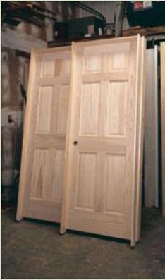
The standard interior door used in most affordable homes is 32 in. wide and has a flat, smooth plywood “skin" that covers a hollow core. But instead of settling for standard hollow-core doors, I recommend shopping around for some frame-and-panel doors made from solid wood. Doors can be a source of beauty in your house, and it may be worth the extra cost to have some well-crafted doors in your favorite doorways. Check with one or more local suppliers, and look at the array of doors that are available. Sometimes, styles are discontinued or doors are special-ordered but never claimed. When that happens, you can find a great door at a bargain price.

MAKING A HOUSE BEAUTIFUL

Most doors open into rooms rather than into a hallway.

They seldom open into closets. They can swing either to the right or to the left. The swing, or hand, of a door can be confusing. Make sure when you order doors that you and your supplier are both on the same page.

Most house plans show which way the doors swing, so it’s not a bad idea to take the plans with you when you order doors.

Different styles of pre­hung doors are used in dif­ferent parts of the country.

I like split-jamb, prehung doors, because they come

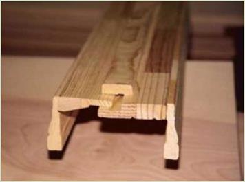
with the trim (casing) installed, and they adjust for uneven wall thicknesses (see the photo at left). Another type of pre­hung door has a knockdown jamb. It comes in three pieces and also has the casing installed. A third style of prehung door has just the jambs but no casing (see the photo above). After the jambs have been nailed in place, the casing must be cut and nailed around them.

Подпись: It is easier to put down underlayment and vinyl floor covering before cabinets are installed.

STEP 2 INSTALL THE INTERIOR DOORS

Once the underlayment is down, start installing the prehung doors. I have lived in older houses that required work on sticky doors, misaligned locks, and squeaky hinges. Quality doors open and close with ease even after years of use—if you take the time to install them with care. Remember that doors and jambs should last for

the life of the house. That won’t happen if you buy junk. Doors and trim are finish work and are seen and used on a daily basis, so try to buy units that are both attractive and durable (see the sidebar above).

The first step in setting prehung doors is to check the plans and see which way they open into a room. It’s helpful to set each door near its opening before nailing any of them in place. This should eliminate installing the wrong door

Quality Control

In framing, the question of speed versus quality always comes up. You want to get the job done as fast as possible—but you must have a quality building, and quality takes time. The most important thing to consider is the structural integrity of the building. Once that requirement is satisfied, the faster the job can be done, the better.

It is a lot easier to talk about the importance of quality than it is to define it for a framer. Quality to one framer can be the product of a “wood butcher" to another framer. Framers learn under different lead framers who have different goals and objectives, and different standards of what quality workmanship is. You need to establish your own definition of quality of workmanship for the framers working for you.

The best way to do this is by observing or auditing their completed work, then giving them feedback on what you saw and what you would like to see.

To audit the work, check a portion of what has been done. If that sample is done well, most likely the rest is done right. If you find a mistake, find out why it was made, correct any similar errors, and make sure the framer knows why this happened.

Audit Checklist

A checklist is helpful when you audit individual tasks. It will help you remember all the parts that need checking. For example, the following list could be used for shear walls.

Audit Guidelines

The following guidelines can be used to control the quality of experienced and new framers’ work, and the work at the end of the job.

For an experienced framer you have worked with before:

1. Casually observe as part of routine.

2. Audit work after completion, or at regular intervals.

For new-to-the-task framers:

1. Review framing tips (at the end of this chapter).

2. When possible, demonstrate work.

3. Watch as the new framer gets started.

4. Ask the new framer to come and get you for review after the first piece is finished.

5. After a half hour to an hour, review the work.

6. End of day: review the work.

7. End of task: audit the work.

End of job:

1. Audit 10% of each individual task.

2. If mistakes are found, review all task work.

3. Correct all mistakes.

4. Check for omissions.

Shear Walls Checklist

□ Nailing pattern for sheathing

□ Blocking, if required

□ Distance between sheathing nails and the edge (3/8n minimum)

□ Nails are not driven too deep

□ Lumber grade, if specified

□ Hold-down sizes and location

□ Hold-down bolt sizes

□ Tightness of bolts

Sample Pick-Up Checklist

□ Studs under beams

□ Drywall backing

□ Fireblocking

□ Nailing sheathing

□ Headers furred out

□ Thresholds cut

□ Crawl space access

□ Attic access

□ Dimensions of rough openings on doors and windows

□ Check door openings for plumb

□ Drop ceilings and soffits framed

□ Stair handrail backing

□ All temporary braces removed

□ Joist hangers and timber connectors

Pick-Up Lists

Pick-up lists are important to keep things organized at the end of the job. The superintendent typically creates this list of tasks that have to be done before you are finished with the job. When the list is first given to you, review it to make sure everything is clear to you. It is sometimes easiest to ask the superintendent to accompany you around the site to make sure you understand exactly what he is trying to communicate.

You may have to consult the plans to get all the information you need in order to understand the work that needs to be done. If the superintendent does not have a written list, make your own list as you walk around the site discussing each task.

Remember that quality control is not just for the owner’s benefit in the finished product. Quality control also makes your work go more smoothly. When your framers’ cuts are square and true to length, the framing fits together a lot more easily.

If the building is square, when you cut joists and rafters, you can cut them all at once, the same length, instead of having to measure each one. When you get to the roof, the trusses will fit.

Blower Doors

Blower doors consist of a sophisticated fan set in an adjustable frame. They are used to test airflow and pressure in a home. There are many uses for blower doors, such as detection of leaks in walls and in heating, ventilation, and air conditioning (HVAC) system duct­work. You can also determine if the ventilation is adequate and identify the location of energy leaks in the structure.

Since the equipment requires extensive training to use, we recommend that you hire a technician to carry out blower door testing. For most new homes this testing will cost sev­
eral hundred dollars. Dollars saved in energy conservation from identified and corrected leaks may soon offset the cost of testing.

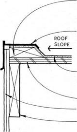
FLAT ROOF EDGE WITH CURB


Single-ply roof—A more recent development in roofing, the single-ply roof is less labor intensive and more elastic than the built-up roof. The single-ply roof is applied as a membrane and glued, weighted with gravel ballast, or mechanically fastened to the roof. Seams are glued with adhesive or heat sealed. Single-ply roofs are usually applied to large areas, but, like the built-up roof, can also cover small areas. Application is technical; warranties start at five years.

Liquid-applied roof—Liquid-applied roofing polymer­izes from chemicals suspended in volatile solvents to form a watertight elastomeric membrane that adheres to the sheathing. Application is usually in several coats, using brush, roller, or spray. Liquid-applied roofs are practical for small areas, where they may be applied by an untrained person without specialized tools; their flexibility allows them to be applied without the cant strips required of built-up roofs (see 178B & C).


NOTE

WALL Framing & SHEATHING NOT SHOWN.


ExTERiOR WALL FINISH LApS METAL FLASHING.

METAL FLASHING WiTH DROp LApS ROOFiNG MATERiAL.

cONTiNuOuS WOODEN

cant strip prevents

RiGHT ANGLES IN ROOFiNG MATERiAL.

ROOFiNG MATERiAL cONTiNuOuS TO ABOVE

cant strip.

ROOF SHEATHING RAFTER


FLAT ROOF EDGE WITH CURBFLAT ROOF EDGE WITH CURB

FLAT ROOF EDGE WITH CURB

Подпись: FLAT ROOFING Introduction FLAT ROOF EDGE WITH CURBFLAT ROOF EDGE AT WALL

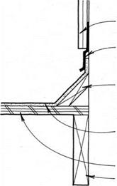
METAL GRAVEL-STOP FLASHiNG SEALED TO ROOFiNG MATERiAL


ROOFiNG MATERiAL CONTiNUOUS TO GRAVEL STOP

ROOF SHEATHiNG

EXTERiOR WALL SHEATHiNG & Finish

ROOF JOIST


NOTE

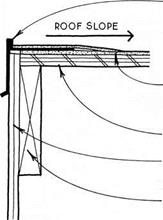
this detail is generally used when THE ROOF slopes away from THE EDGE TOWARD A cENTRAL DRAIN. SEE 179b


to attached drainpipe.


TO ROOF SHEATHiNG.


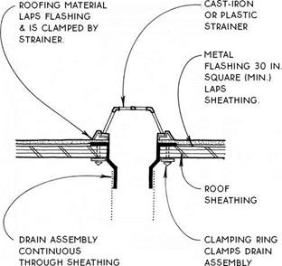
FLAT ROOF DRAIN


) FLAT ROOF EDGE WITH GRAVEL STOP


FLAT ROOF EDGE WITH CURBFLAT ROOF EDGE WITH CURB

Roll roofing is an inexpensive roofing for shallow – pitch roofs (1-in-12 to 4-in-12). The 36-in. wide by 36-ft. long rolls are made with a fiberglass or organic felt base that is impregnated with asphalt and covered on the surface with mineral granules similar to asphalt shingles. Several colors are available. Roll roofing weighs 55 lb. to 90 lb. per square (100 sq. ft.). The average life expectancy for roll roofing ranges from 10 to 15 years; fiberglass-base roofing is the longest lasting. Fiberglass-base rolls are also more resistant to fire. A disadvantage of all roll roofing is that it can bubble upward when hot because, unlike asphalt shin­gles, it cannot adjust to dimensional change.

Roll roofing must be applied over solid sheathing and does not require underlayment. It is easily nailed in place without using any specialized equipment.

There are two basic types of roll roofing, single cov­erage and double coverage.

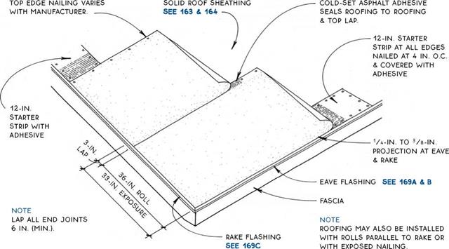
Single coverage—Single-coverage roofing rolls are uniformly surfaced with mineral granules and are applied directly to the roof sheathing with only a 2-in.

to 4-in. lap, which is sealed with roofing adhesive. The rolls may be parallel to the eaves or to the rake. The roofing may be applied using the concealed-nail method (see 180B) or the exposed-nail method (not shown). A minimum pitch of 2-in-12 is required for the exposed – nail method. Single coverage is the least expensive and the least durable of the roll-roofing methods.

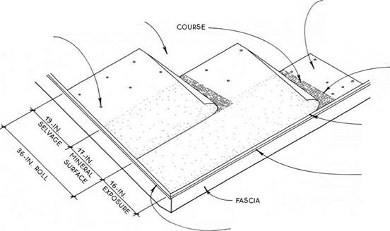
Double coverage—Double-coverage rolls are half surfaced with mineral granules and half smooth. The smooth part of the roll is called the selvage. The rolls are lapped over each other so that the surfaced por­tion of each roll laps over the smooth portion of the previous course. Each course of roofing is sealed to the previous course with either cold asphalt adhesive or hot asphalt. In this fashion, the roof is covered with a double layer of felt. The double layer of felt weighs 110 lb. to 140 lb. per square. Double-coverage roofing is more expensive than single-coverage roofing, but it makes a more durable roof. Double-coverage roll roofing may be applied with the courses parallel to the eave or to the rake (see 181A).

ROLL ROOFING

Introduction


FLAT ROOF EDGE WITH CURBFLAT ROOF EDGE WITH CURB

SINGLE-COVERAGE ROLL ROOFING

Conceded-Nail Method

NAiLS iN SELVAGE PORTiON OR ROLL PER

MANUFACTURER’S iNSTRUCTiONS


SOLiD ROOF SHEATHiNG SEE 163


COLD-SET ASpHALT Adhesive between selvage & mineral surface portion OF each


19-iN. selvage starter strip cut FROM TOp OF ROLL & NAILED TO SHEATHiNG

per manufacturer’s instructions


lap all

END JOINTS 6 IN. (MIN.).


1A-IN. TO 3/8-IN.

projection AT

EAVE & RAKE


EAVE FLASHING SEE 169A & В


NOTE

ROOFING MAY ALSO BE INSTALLED WITH ROLLS pARALLEL TO RAKE.


RAKE FLASHING SEE 1690


FLAT ROOF EDGE WITH CURB

Подпись:Подпись: SINGLE (SHOWN) OR DOuBLE-cOVERAGE ROLL ROOFINGПодпись: NOTE RIDGE DETAIL IS SIMILAR TO Hip DETAIL. FLAT ROOF EDGE WITH CURB

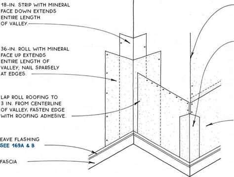
Подпись: 12-IN. X 36-IN. STRip cuT FROM DOuBLE cOVERAGE ROOFING MATERIAL; MINERAL-SURFACE PORTION LAPS ONTO SELVAGE pORTiON NAILED PER MANUFACTURER'S DIRECTIONS AND COATED WITH ASPHALT ADHESIVE AS FOR DOuBLE-cOVERAGE ROOF.

дЛ DOUBLE-COVERAGE ROLL ROOFING

ROLL-ROOFING VALLEY & HIP (OR RIDGE)

Double or Single Coverage

Composite asphalt shingles are almost the perfect roofing material. They are inexpensive, waterproof, lightweight, and easily cut and bent. That is why asphalt shingles are so popular nationwide. They are available in a wide range of colors and textures, some with extra thickness to imitate shakes, slate, or other uneven materials. There is also a range of quality, with warran­ties from 15 to 30 years.

Asphalt shingles have a fiberglass or organic-felt base that is impregnated with asphalt and covered on the surface with granulated stone or ceramic material, which gives them color. Shingles made with fiberglass are more durable and more resistant to fire than those of organic felt.

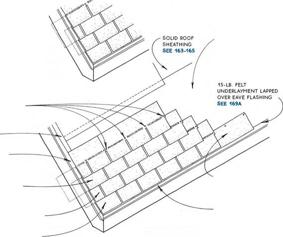
Asphalt shingles must be applied over a solid sheathing covered with 15-lb. felt underlayment. They are easily nailed in place, using no specialized equip­ment. Many roofing contractors, however, use air – driven staples.

drip edge laps underlayment at rake.

rake flashing SEE 169c

THIRD course STARTS with full shingle minus one tab

FIRST course STARTS with full shingle

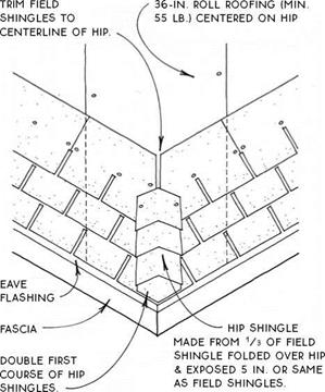
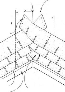
Подпись:Подпись: STANDARD FIELD SHINGLES MAY BE CUT INTO 3 PIECES TO MAKE Hip OR RiDGE SHiNGLES.Подпись: SELF-SEALING ADHESIVE AVAILABLE ON TOP SIDE OF SHiNGLES TO pRoTECT AGAINST WIND.Подпись: ALTERNATIVE PATTERNS AVAILABLE WITH SOME THICKER TABS TO RESEMBLE MORE NATURAL ROOFS.Подпись: Common Shingle OTHER LESS COMMON Patterns PATTERNS ARE ALSO AVAILABLE. Подпись: ALTERNATIVE STARTING PATTERN (SEE BELOW FOR SIMPLER SHINGLE PATTERN) REMOVES 4 IN. FROM SECOND COURSE & 8 IN. FROM THIRD COURSE. FOURTH COURSE STARTS WITH FULL SHINGLE MINUS ONE FULL TAB. Подпись: 4 NAILS PER SHINGLE LOCATED ABOVE SLOTS & INDENTATIONSПодпись: SECOND COURSE STARTS WITH FULL SHINGLE MINUS 1/2 TAB Подпись: CODES IN COLD CLIMATES OFTEN REQUIRE A 36-IN. STARTER STRIP OF BITUMINOUS WATERPROOFING. SEE 169B Подпись: STARTER COURSE WITH TABS CUT OFF TO BE OFFSET 3 IN.Подпись: EAVE FLASHING SEE 169A & BПодпись: FOR Hip, VALLEY & RiDGE DETAILS, SEE 183.FLAT ROOF EDGE WITH CURBASPHALT-SHINGLE ROOFING

FLAT ROOF EDGE WITH CURBПодпись: ASPHALT-SHINGLE HIPПодпись:Подпись: 36-iN. RoLL ROOFING (MIN. 55 LB.) CENTERED ON VALLEYПодпись: EAVE FLASHING FASCIA Подпись:FLAT ROOF EDGE WITH CURBEXTEND SHiNGLES 12 iN. (MiN

beyond centerline of valley.

Thermal Imaging

Thermal imaging using infrared cameras has rapidly become an affordable tool for diagnos­ing moisture problems. This versatile tool is also used for energy conservation audits (see the next section) and can detect overloaded electrical circuits, poor electrical connections, and “hot spots” on electrical equipment that may indicate a potential failure or fire hazard.

Infrared cameras are sophisticated devices that are used to examine the spectrum of en­ergy just outside our visual range. They “see” heat. We see the colors of the rainbow: violet, blue, green, yellow, orange, and red. Infrared is the portion of the spectrum just beyond red, which we can t see but can certainly feel with our skin in the form of heat.

Thermal imaging can frequently diag­nose moisture from leaks and condensation because damp surfaces are subject to evapo­rative cooling, resulting in cooler surface tem­peratures. Since thermal imaging uses surface temperature differences to indicate potential issues, moisture and missing insulation may appear the same. Thus moisture problems generally must have further diagnosis using moisture meters to confirm and identify the source of the moisture, but as a first screening step thermal imaging can help tremendously.

Energy Efficiency and Airflow Testing

Thermal Imaging for Energy Conservation Audits

When used by a knowledgeable, trained ther – mographer, an infrared camera can detect heat loss from missing insulation, air infiltration, and leaking ductwork. The US Department of Energy’s Office of Energy Efficiency and Re­newable Energy is now recommending that anyone purchasing a home have it scanned as part of the escrow. They advise: “Even new houses can have defects in their thermal en­velopes. You may wish to include a clause in the contract requiring a thermographic scan of the house”1

For thermal imaging to be most effective, there needs to be a temperature difference. In evaluations of ductwork and heating or air conditioning systems, the temperature dif­ferential is provided by the equipment being evaluated. In evaluations of energy efficiency from thermal insulation and of air infiltra­tion, there needs to be a sharp temperature

Подпись: The Problem: This furnace ductwork, located in an attic, was not firmly connected to the supply register. As a result heat is being lost in the living space and insulation fibers are being blown into the air resulting in poor indoor air quality. Recommendation: ductworks must be well sealed and tested for air leakage. Photo: Restoration Consultants.

difference between the inside and outside en­vironments. Inspections of this type will be most effective when performed during the hot summer or cold winter months when there is at least a 20-degree Fahrenheit temperature difference between the inside and the outside of the building.

Bridge in Wroclaw, Poland

The bridge in Wroclaw, Poland, is a steel construction with short spans but sub­stantial deflections and vibrations. A completely new pavement was laid in 1997. It consisted of an asphalt mastic protection layer (2 cm) and two 0/8 mm SMA layers—the first one as an intermediate layer and the second one as a wearing course. The mastic layer was spread manually, whereas both SMA courses were

(a) (b)

image157

FIGURE 13.2 The bridges in Plock and Wroclaw: (a) condition of the Plock bridge pavement; (b) condition of the Wroclaw bridge pavement. (Photos courtesy of Krzysztof BlaZejowski.)

laid mechanically. An SBS modified binder—with 50/80 Pen@25°C, SP > 53°C, and ER > 50%—was used in all the asphalt layers. The condition of the pavement after 13 years in operation was still good, with no cracks or potholes (Figure 13.2.b). Slight rutting was observed (the bridge is located at the approach to a crossing with traffic lights), but repair was needed only in the area of the joints.

There Are All Kinds of Ways to Cut a Beam

There Are All Kinds of Ways to Cut a Beam

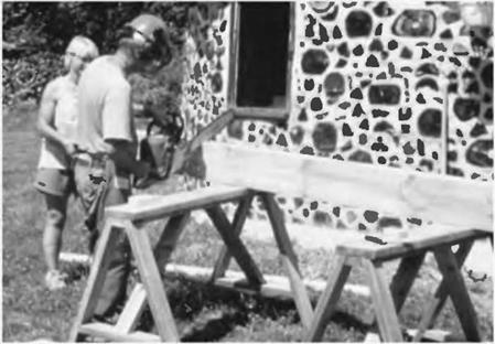
Chainsaw

image132

Fig. 5.25: Chainsaw. The author cuts a heavy timber supported at a convenient height by sawhorses. The saw cut can be no better than:

1. The accuracy with which the pencil marks are trans­posed to the timber. Use a good carpenter’s square and mark all around the timber, to make sure that — after its circumnavigation — the mark returns to the point of beginning. If it doesn’t, the cut cannot be square. Always set your square on the beam being cut, not on the piece being cut off.

2. The quality of the chain and bar. The right – and left-side chain teeth must be sharpened equally to prevent pull to either direction, and the bar must be straight, with a clean, un-nicked groove.

3. The skill of the operator. In this regard, I can only say: Practice, practice, practice! Always cut on the long side of the line. A chainsaw removes about a quarter inch of wood. This is called the kerf. Don’t make your post a quarter inch short!

Note the use of a chainsaw safety helmet for sound and kickback protection, as well as to keep wood chips out of your eyes. Use protective leg chaps in case the saw cuts through the timber and continues on to your knees and legs.

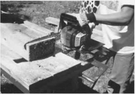
Cutoff saw

image133

Fig. 5.26 Cutoff saw. This cutoff saw moves the chain through a vertical arc, perpendicular to the timber on the table. This advantage makes it easier to maintain a consistently straight cut.

There are also 24-inch circular saws made for crosscutting, also called beam cutters or compound miter saws. Log cabin builders and professional timber framers use these all the time. Contractor Russell Pray owns one of these and used it to make perfect right- angle cuts on the posts and beams at the Earthwood garage. They are very expensive, though, and it would make more economic sense to hire one for a day from a contractor’s tool rental store rather than buy one.

Подпись: The following option is much more affordable.Подпись: Crosscut saw attachment for a circular sawПодпись: Fig. 5.27. The Prazi Beam Cutter. Photo supplied by Prazi USA. A great new development in crosscutting is the Linear Link™ power saw from Muskegon Power Tool (see Appendix C for contact information for Muskegon and also for Prazi, a manufacturer of a similar tool, the Beam Cutter™.) The tool combines the best features of a chainsaw and a circular saw, allowing straight cuts up to 12 inches (30.5 centimeters) deep on vertical cuts, and well over 8 inches (20.3 centimeters) deep on a 45- degree angle cut. You can buy the complete unit for about $540 (March 2003) or, for about $220, you can buy a conversion kit for your Skil™ or Craftsman™ worm drive circular saws. (The $130 Prazi unit will fit Makita and DeWalt "sidewinders" as well.) This sturdy chain kit can replace your circular saw blade in a few minutes, and enables you to make deep accurate crosscuts through beams up to a foot thick. Think of the accuracy and convenience of a circular saw, combined with the depth of a chainsaw. It can even be used to do minor "saw milling," if you need to rip an inch or two off the edge of a beam. (For major saw milling, use one of the chainsaw mills described in Chapter 3.)
Circular saw and handsaw

image135

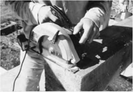
Fig. 5.28: Circular saw and handsaw. After marking the square cut all the way around with a pencil and square, use a circular saw to cut as deeply as possible into all four surfaces, all the way around the beam and back to the original side. My seven-inch (17.8- centimeter) circular saw will allow me to make a vertical cut 2-1/2 inches (6.3 centimeters) deep, maximum. With an eight-by-eight, cutting into all four surfaces will leave a square of uncut wood in the center about three inches (7.6 centimeters) square, which you can finish with a good sharp handsaw. The cuts made with the circular saw will guide your handsaw straight through.

When you think you’ve got a good square base on your post, try it at its actual location to see if it stands up vertically. If it is good, measure (twice!) and make the square cut at the top end. Don’t be nervous — timber framing for the rest of us is quite forgiving, unless you happen to be a card-carry­ing obsessive-compulsive neat freak. Tapered cedar shingles will tighten up any joint, and can often be hidden, or at least sanded smooth and rendered almost invisible.

Once the post is the right length, stand it in place. Fastening to concrete foundations was discussed in Chapter

4. In our sunroom, we were standing the post onto a wooden substrate, the two-by-six tongue-and-groove floor.

In Fig. 5.29 Jaki and Anna plumb a post. We felt we had a good square cut on this one, yet it still wanted to lean in slightly. Anna tapped in the thin edge of an eight-inch-wide cedar shingle, while Jaki consulted the plumb bubble of her four-foot level. In Fig. 5.30,1 toe – screw the post in place, a couple of screws each side. Right angle connectors are another option here.

Because of the odd angles where girders meet on the south wall (please revisit Fig. 5.2), two of the posts required some custom work at the sawmill. I used my angle square to capture this angle, and transposed it to the ends of a couple of six- by-eight posts, already made. I took the timbers back to the sawmill and showed Norm, the sawyer, how the post needed to be ripped on the bias so that, when placed up against its neighbor, the resulting “double-wide” post makes the slight angle turn in the wall. Norm loves this sort of challenge, and clamped the piece onto his movable carriage with shims to create the angle. In no time, I had the
required posts with their trapezoidal

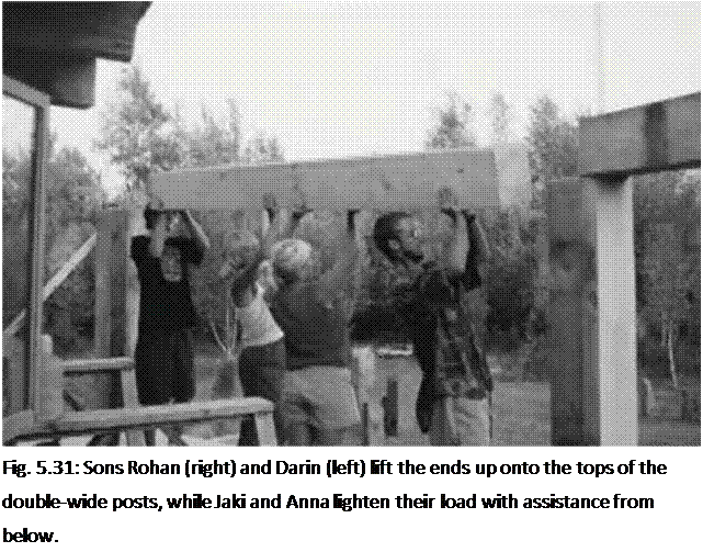
Подпись: Fig. 5.31: Sons Rohan (right) and Darin (left) lift the ends up onto the tops of the double-wide posts, while Jaki and Anna lighten their load with assistance from below. cross-sections.

Installing the Girders

The posts are all installed — and braced — and the girders have had their angles cut as described above (see Preparing the Girders, pages 121—122).

Now it is time to blow the whistle on some muscle and heft the girders into place. We had enough help right in the family so that I could hide behind the camera. By the way, I think of these beams as girders, because they support

rafters, but, as they are on the edge of a building, they can also be called girts.

We started with the west girder, letting the west end run long. Its overhang could be cut to length later in situ. We did not fasten it yet, for its own weight kept it in place. The second one — the central girder — was the really heavy one: a ten-foot six-inch full-sized eight-by-ten of fairly green white pine. But many hands make light work. See Fig. 5.31.

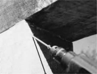
Подпись: Fig. 5.32: A couple of screws hold the girder in place. Right-angle connectors are good in this situation, too.image139After all three girders were set in place, we adjusted their positions slightly with a heavy hammer, sliding them this way and that until we were happy with the way they sat and joined each other. Small wooden shingle shims can be used as necessary to take any wobbles out. Then I toe-screwed up through the posts into the underside of the girders, using two screws at each side of a post. Fig. 5.32. I made a mistake at this point that you can avoid. I should have fastened the top sides of the girders together with truss plates, as I had done many times before. I either forgot to do this, or felt it wasn’t necessary, or thought that the truss plates might get in the way of rafters later on; I really don’t remember. (And excuses are like belly buttons; everybody has one.)
But the girders did separate by about a quarter inch (6.3 millimeters) later on. This is a cosmetic — as opposed

NONGRAVITY CANTILEVERED WALL DESIGN

Nongravity cantilevered walls are those that provide lateral resistance through vertical elements embedded in soil, with the retained soil between the vertical elements usually supported by facing elements. Such walls may be constructed of concrete, steel, or timber. Their height is usually limited to about 15 ft (4.6 m), unless provided with additional support anchors.

8.6.1 Earth Pressure and Surcharge Loads

Lateral earth pressure can be estimated assuming wedge theory using a planar surface of sliding as defined by Coulomb’s theory. For permanent walls, effective stress meth­ods of analysis and drained shear strength parameters for soils can be used for deter­mining lateral earth pressures. Alternatively, the simplified earth pressure distributions shown in Figs. 8.45 and 8.46 can be used. Nomenclature and notes for Fig. 8.45 are given in Table 8.8.

FIGURE 8.45 Simplified earth pressure distributions for permanent flexible cantilevered walls with discrete vertical wall elements. (a) Embedment in soil; (b) embedment in rock. Note: Refer to Table 8.8 for general notes and legend. (From Standard Specifications for Highway Bridges, 2002, American Association of State Highway and Transportation Officials, Washington, D. C., with permission)

1. Determine the active earth pressure on the wall due to surchage loads, the retained soil, and differential water pressure above the dredge line.

2. Determine the magnitude of active pressure at the dredge line (P*) due to surcharge loads, retained soil, and differential water pressure, using the earth pressure coefficient Ka2.

3. Determine the value of x = P*/[(Kp2 – Ka2)y2] for the distribution of net passive pressure

in front of the wall below the dredge line.

4. Sum moments about the point of action of F to determine the embedment (D0) for which the net passive pressure is sufficient to provide equilibrium.

5. Determine the depth (point a) at which the shear in the wall is zero (i. e., the point at which the areas of the driving and resisting pressure diagrams are equivalent).

6. Calculate the maximum bending moment at the point of zero shear.

7. Calculate the design depth, D = 1.2 D0 to 1.4 D0, for a safety factor of 1.5 to 2.0.

(a) Pressure distribution (b) Simplified design procedure

N°tes: (1) Surcharge and water pressures must be added to the above earth pressures.

(2) Forces shown are per horizontal foot of vertical wall element.

FIGURE 8.46 Simplified earth pressure distributions and design procedures for permanent flexible cantilevered walls with continuous vertical wall elements. (From Standard Specifications for Highway Bridges, 2002, American Association of State Highway and Transportation Officials, Washington, D. C., with permission)

For temporary applications in cohesive soils, total stress methods of analysis and undrained shear strength parameters apply. The simplified earth pressure distributions shown in Figs. 8.46 and 8.47 can alternatively be used with the following limitations:

1. The ratio of overburden pressure to undrained shear strength must be less than 3. This ratio is referred to as the stability number N = yH/c.

2. The active earth pressure must not be less than 0.25 times the effective overburden pressure at any depth.

Nomenclature and notes for Fig. 8.47 are given in Table 8.8.

Where discrete vertical wall elements are used for support, the width of each vertical element should be assumed to equal the width of the flange or diameter of the element for driven sections, and to equal the diameter of the concrete-filled hole for sections encased in concrete.

For permanent walls, Figs. 8.45 and 8.46 show the magnitude and location of resultant loads and resisting forces for discrete vertical elements embedded in soil and rock. The procedure for determining the resultant passive resistance of a vertical element assumes that net passive resistance is mobilized across a maximum of 3 times the element width or diameter (reduced, if necessary, to account for soft clay or discontinuities in the embedded depth of soil or rock). Also, a depth of 1.5 times the width of an element in soil, and 1 ft (300 mm) for an element in rock, is ineffective in providing passive lateral support.

Legend:

y’ = effective unit weight of soil b = vertical element width

l = spacing between vertical wall elements, center to center S = undrained shear strength of cohesive soil s = shear strength of rock mass Pp = passive resistance per vertical wall element P = active earth pressure per vertical wall element p = ground surface slope behind wall 1 + for slope up from wall

p’ = ground surface slope in front of wall J — for slope down from wall Ka = active earth pressure coefficient; refer to Art. 8.2.3

K = passive earth pressure coefficient; refer to Standard Specifications for Highway Bridges,

P AASHTO, 2002. ф’ = effective angle of soil friction

Notes:

1. For temporary walls embedded in granular soil or rock, refer to Fig. 8.45 to determine passive resis­tance and use diagrams on Fig. 8.47 to determine active earth pressure of retained soil.

2. Surcharge and water pressures must be added to the indicated earth pressures.

3. Forces shown are per vertical wall element.

4. Pressure distributions below the exposed portion of the wall are based on an effective element width of 3b, which is valid for l > 5b. For l < 5b, refer to Figs. 8.46 and 8.48 for continuous wall elements to determine pressure distributions on embedded portions of the wall.

Source: From Standard Specifications for Highway Bridges, 2002, American Association of State Highway

and Transportation Officials, Washington, D. C., with permission.

FIGURE 8.47 Simplified earth pressure distributions for temporary flexible cantilevered walls with discrete vertical wall elements. (a) Embedment in cohesive soil retaining granular soil; (b) embedment in cohesive soil retaining cohesive soil. Note: Refer to Table 8.8 for general notes and legend. (From Standard Specifications for Highway Bridges, 2002, American Association of State Highway and Transportation Officials, Washington, D. C., with permission)

(a) Embedment in cohesive soil (b) Embedment in cohesive soil

retaining granular soil retaining cohesive soil

Notes: (1) For walls embedded in granular soil, refer to Fig. 8.46 and use above diagram for retained cohesive soil when appropriate.

(2) Surface and water pressures must be added to the above earth pressures.

(3) Forces shown are per horizontal foot of vertical wall element.

FIGURE 8.48 Simplified earth pressure distributions for temporary flexible cantilevered walls with continuous vertical wall elements. (From Standard Specifications for Highway Bridges, 2002, American Association of State Highway and Transportation Officials, Washington, D. C., with permission)

The design lateral pressure must include lateral pressure due to traffic, permanent point and line surcharge loads, backfill compaction, or other types of surcharge loads, as well as the lateral earth pressure.

Cutting and installing risers and treads

If the stairs are going to be covered with carpet, the treads and risers can be cut from scrap material leftover from sheathing. I use at least 5/s-in. plywood or oriented strand board (OSB) for the risers and 3/нп. plywood for treads.

Scrap material can be ripped to width on a table saw or with a circular saw (care­fully following a chalkline or using a ripping guide).

These rough treads and risers can also be covered with a fine, finished hard­wood to give the stairs a custom look. Often, this is done later, when the house is nearly finished. To help you get a perfect fit, use a stair-tread gauge, a tool that fits from wall to wall, adjusts to fit out-of-square skirtboards, and gives you the exact length and shape of the tread or riser. Finish treads often have a nosing (174-in. maximum over­hang by code) that projects out over the edge of each tread. I think that 174 in. is excessive because it is too easy to catch your toe on it as you go up the stairs, so I prefer no more than a 7/s-in. overhang.

Rough risers and treads don’t have to be the exact width when they’re being cov­ered by carpet. In fact, it’s better to cut them a bit narrow to eliminate the possi­bility that they will touch at the back side and create a squeak, which can happen when wood rubs against wood. And who needs squeaky stairs, especially if you’re trying to sneak in late at night? So for stairs with 774-in. risers and 10-in. treads, rip the risers to 77s in. and the treads to 97/s in. Cut them to the width of the rough stairway, or 36 in. long in this case.

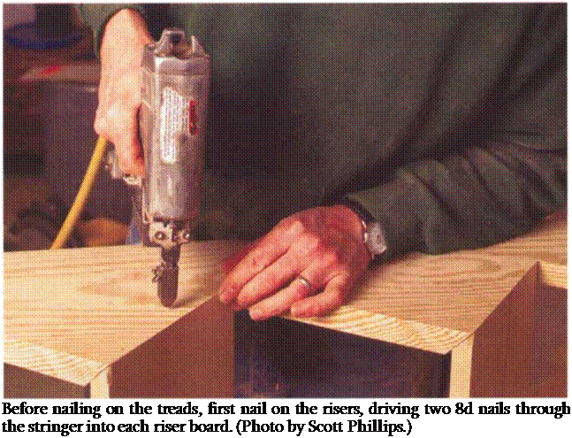
Risers are nailed on first (see the photo on p. 168). The first riser usually has to be ripped an extra 3/4 in. narrower than

Подпись: Before nailing on the treads, first nail on the risers, driving two 8d nails through the stringer into each riser board. (Photo by Scott Phillips.)

the rest to compensate for the dropped stringer. Starting at the bottom, drive two 8d nails through the riser board into each stringer. Put the next riser in the same way, halfway up, to help straighten the stringers. Then go back to the bottom and nail on the rest of the risers.

When fastening the treads, use lots of construction adhesive between the treads and the stringers to help prevent squeaks that can develop as the wood dries out and nails loosen up. For extra insurance, secure the treads with deck screws, which are less likely to pull out than nails. Start at the bottom, run a generous bead of adhesive on the stringers and on the riser edge and secure each board as you go with three 8d nails or screws per stringer. When all the treads are on, try out the stairs. Finally, take a moment to admire the safe, easy access you have built to the next floor.

Estimating Maximum Reinforcement Load Using the ^-Stiffness Method

According to the K0-Stiffness Method, with reference to Dt from Fig. 8.44a and b, the peak load, Tmax (lb/ft), in each reinforcement layer can be calculated with the procedure summarized below (Allen and Bathurst, 2001):

Ф(ь = facing batter factor Ф(8 = facing stiffness (actor

Pa = atmospheric pressure (a constant to preserve dimensional consistency equal to 2110 lb/ft2 for the indicated units)

^global- ^ocal> Ф(Ь Ф(8> and are further defined bel°W.

K0 can be determined from the coefficient of lateral at-rest earth pressure for nor­mally consolidated soil:

K0 = 1 – sin Ф’ (8.17)

where Ф’ (degrees) is the peak angle of internal soil friction for the wall backfill. For steel reinforced systems, K0 for design should be 0.3 or greater. This equation for K0 has been shown to work reasonably well for normally consolidated sands, and can be modified by using the overconsolidation ratio (OCR) for sand that has been preloaded or compacted. However, because the OCR is very difficult to estimate for compacted sands, especially at the time of wall design, the K0-Stiffness Method was calibrated using only Eq. (8.17) to determine K0. Because the K0-Stiffness Method is empirically based, it can be argued that the method implicitly includes compaction effects, and therefore modification of Eq. (8.17) to account for compaction is not necessary. Note also that the method was calibrated using measured peak shear strength data corrected to peak plane strain shear strength values.

Global stiffness 5global considers the stiffness of the entire wall section, and is calcu­lated as follows:

= Hve = sumof Jj

global = H/n = H

where Jave (lb/ft) is the average modulus of all reinforcement layers within the entire wall section, Jt (lb/ft) is the modulus of an individual reinforcement layer, H is the total wall height, and n is the number of reinforcement layers within the entire wall section.

Local stiffness Slocal (lb/ft2) considers the stiffness and reinforcement density at a given layer, and is calculated as follows:

Slocal = H (8Л9)

where J is the modulus of an individual reinforcement layer, and Sv is the vertical spacing of the reinforcement layers near a specific layer.

The local stiffness factor Ф^^ is defined as

Ф^ = ( Hh ) (8.20)

global

where a is a coefficient that is also a function of stiffness. Observations from available data suggest that setting a = 1.0 for geosynthetic-reinforced walls and a = 0.0 for steel-reinforced soil walls is sufficiently accurate.

The wall face batter factor Ф(Ь which accounts for the influence of the reduced soil weight on reinforcement loads, is determined as follows:

Ф(ь = ( Hh ) (8.21)

Kavh /

where Kabh is the horizontal component of the active earth pressure coefficient accounting for wall face batter, Kavh is the horizontal component of the active earth pressure coefficient, and d is a constant coefficient (recommended to be 0.5 to provide the best fit to the empirical data). The wall is assumed to be vertical.

The facing stiffness factor Фй was empirically derived to account for the signifi­cantly reduced reinforcement stresses observed for geosynthetic walls with segmental concrete block and propped panel wall facings. It is not yet known whether this facing stiffness correction is fully applicable to steel-reinforced wall systems. On the basis of data available, Allen and Bathurst (2001) recommend that this value be set equal to the following:

0. 5 for segmental concrete block and propped panel faced walls

1. for all other types of wall facings (e. g., wrapped face, welded wire or gabion faced, and incremental precast concrete facings)

1.0 for all steel-reinforced soil walls

Note that the facings defined above as flexible still have some stiffness and some ability to take a portion of the load applied to the wall system internally. It is possible to have facings that are more flexible than the types listed above, and consequently walls with very flexible facings may require a facing stiffness factor greater than 1.0.

The maximum wall heights available where the facing stiffness effect could be observed were approximately 20 ft (6 m). Data from taller walls were not available. It is possible that this facing stiffness effect may not be as strong for much taller walls. Therefore, caution should be exercised when using those preliminary Фй values for walls taller than 20 ft (6 m). Detailed background information as well as several numerical examples for both steel and geosynthetic reinforced soil walls are provided by Allen and Bathurst (2001).

The following is a numerical example of applying the preceding equations for the evaluation of Tmax at reinforcing layers 4 ft (1.2 m), 10 ft (3 m), and 18 ft (5.5 m) from the top of the wall.

• Design assumptions

A 20-ft-high (6-m) segmental concrete block MSE wall has a vertical facing and 10 layers (2-ft or 0.6 m uniform spacing) of the same grade polyester (PET) geogrid reinforcements. Thus, H = 20 ft (6 m), Фй = 0.5, n = 10, Sv = 2 ft (0.6 m), and Jave = 28,780 lb/ft (420 kN/m) for PET. Since the wall is vertical, Kabh/Kavh = 1.0. The wall has a 2-ft earth surcharge, soil with 125 lb/ft3 unit weight, and 34° peak soil friction angle. Thus, S = 2 ft, у = 125 lb/ft3, Ф = 34°, and Pa = 101 kPa = 101 kN/m2 = 2110 lb/ft2.

• Computations

From Eq. (8.17), K0 = 1 – sin 34° = 0.441.

From Eq. (8.18), Sglobal = (28,780)/(20/10) = 14,390 lb/ft2.

From Eq. (8.19), Slocal = 28,780/2 = 14,390 lb/ft2.

From Eq. (8.20), Ф^ = (14,390/14,390)’ = 1.0.

From Eq. (8.21), Фл = (1.0)05 = 1.0.

From Eq. 8.16, for the K0-Stiffness Method, Tmax = 0.5 (Sv)(0.441)(125)(20 + 2)(DtmJ(1.0) (1.0)(0.5)(0.27)(14,390/2110)°’24 = (129.8)(Sv)(D^).

Next, evaluate Tmax at distances Z from the top of the wall, obtaining the distribution factor Dtmax from Fig. 8.44 for each Z/H ratio: At 4 ft, Z/H = 0.2, Dtmx = 0.733, Tmax =

95.1 (Sv) “lb/ft2 = 190.2 lb/ft; at 10 ft, Z/H = 0.5, Dtmax = 1.00, Tmax =129.8 (Sv) lb/ft2 = 259.6 lb/ft; and at 18 ft, Z/H = 0.9, D, = 0.60, T = 83.8 (S ) lb/ft2 = 167.6 lb/ft.

tmax ‘ max x V’

If the results for this example are compared with those obtained by the AASHTO method (Art. 8.5.11), it will be seen that the total required reinforcement forces for the ^-Stiffness Method are only about one-quarter of those for the AASHTO method.

With the assumption that all the 10 reinforcement layers have the same stiffness, the calculation of reinforcement forces demonstrated above is a first trial. The global stiffness factor (Sglobal) should be revised according to the actual reinforcing stiffness distribution. To avoid the iterative nature of the ^-Stiffness Method, Allen and Bathurst (2001) also provide a simplified methodology with different combined global stiffness curves according to the type of reinforcing material as well as the height of wall.