Earth Pressure and Surcharge Loadings
The choice of lateral earth pressures used for design should take into account the method and sequence of construction, rigidity of the wall-anchor system, physical characteristics and stability of the ground mass to be supported, allowable wall deflections, space between anchors, anchor prestress, and potential for anchor yield. For stable ground masses, the final lateral earth pressures on a completed wall with two or more levels of anchors constructed from the top down can be calculated using the apparent earth pressure distributions shown in Fig. 8.50. For unstable or marginally stable ground masses, design earth pressures will be greater than those shown in Fig. 8.50. Therefore, loads
SOIL TYPE PRESSURE DISTRIBUTION
H = final wall height Ka = active earth pressure coefficient
Y = effective soil unit weight
Y = total soil unit weight m = reduction factor
qu = unconfined compressive strength
(1) Ka = tan2 (45 – 2 )
(2) Ka = 1 – m (2qu/yH) but not
less than 0.25
m = 1 for overconsolidated clays
m = 0.4 for normally consolidated clay
(3) Value of 0.4 should be used for long-term excavations; values between 0.4 and 0.2 may be used for short-term conditions.
should be estimated using methods of slope stability analysis that include the effects of anchors, or that consider “interslice” forces.
In developing design earth pressures, consideration should be given to wall displacements that may affect adjacent structures or underground utilities. Rough estimates of settlement adjacent to braced or anchored flexible walls can be made using Fig. 8.51. If wall deflections estimated using Fig. 8.51 are excessive, a more detailed analysis can be made using beam-on-elastic-foundation, finite element, or other methods of analysis that consider soil-structure interaction effects. Where a structure or utility particularly sensitive to settlement is located close to a wall, wall deflections should be calculated on the basis of the loading, soil properties, anchor spacing, and wall element stiffness.
The distribution of earth pressure loading for anchored walls with one level of anchors can be assumed to be triangular and to be based on a lateral earth pressure coefficient (i. e., Ka, K0, or Kp) consistent with the expected wall deflection. To consider the case where excavation has advanced down to the first anchor level but the anchors have not yet been installed, the wall can be treated as a nongravity cantilevered wall and the earth pressure distribution assumed triangular. Overstressing of anchors
CURVE I
CURVE E = Stiff to very hard clay
CURVE Ш = Soft to medium day, factor of
safety against basal heave (5-1 equal to 2.0 ”У ” 4
CURVE Ш. = Soft to medium clay, factor of
safety agoinst basal heave (= 5-’ su ^ equol to 1.2 yH + q у
FIGURE 8.51 Settlement profiles behind braced or anchored walls. (From Standard Specifications for Highway Bridges, 2002, American Association of State Highway Officials, Washington, D. C., with permission)
should be avoided, because excessive anchor loads, relative to the capacity of the retained ground mass, can cause undesirable deflections, or passive failure of the wall into the retained soil. As with other walls, design lateral pressures for walls constructed from the top down must include the lateral pressure due to traffic or other surcharge loading.
Where there is no anchor level or only one, the magnitude and distribution of lateral resisting forces for embedded vertical elements in soil or rock can be determined as described in Art. 8.6.1. When two or more levels of anchors have been installed, the lateral resistance provided by embedded vertical elements will depend on the element stiffness and deflection under load.
Earth pressures on anchored walls constructed from the bottom up (fill construction) are affected by the construction method and sequence. These must be well specified, and the basis for lateral earth pressures fully documented. For walls with a single anchor level, consider a triangular distribution, defined by Kay per unit length of wall height, plus surcharge loads. For walls with multiple anchor levels, consider a rectangular pressure distribution, derived by increasing the total force from the triangular pressure distribution just described by one-third and applying the force as a uniform pressure distribution.
Drainage considerations for anchored walls are similar to those discussed in Art. 8.6.2.



 in. Workers occasionally exposed to lead dust should wear at least an N100 disposable respirator. Disposable coveralls, gloves, and booties are also a must; tape shut neck, wrist and ankle openings. Finally, change out of lead-dust – contaminated work clothes at work because wearing them home can endanger your family.

 Pressure water pipe has been constructed of concrete, vitrified clay, lead, ductile iron, cast iron, asbestos cement, and wood. The newest material, plastic, most often in the form of polyvinyl chloride (PVC) or polybutylene (PB), has performed equally well or better than many of the more "traditional" materials.
 Although local acceptance of plastic has been a slow process, both materials have been recognized under the major model plumbing codes. Available from most local suppliers, PB and PE have been rated at pressures well above those encountered in public water systems. Plastic tubing is flexible, lightweight, and easily joined with standard fittings. The relatively long lengths of most tubing insure that the number of joints will generally be limited to those at the main and the meter.


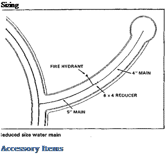 Many communities’ standards require a 6-inch, 8-inch, or even 10-inch minimum diameter for water mains. This often produces an overdesigned system.



 Mike Robinson, President of Black Bull Enterprises, proposed substituting PVC water mains in place of the standard DIP in the North Meadow Village demonstration subdivision, and downsizing the water main from 8-inch lines to 6-inch fire hydrant and 4-inch domestic water lines, depending on the location. The city allowed both deviations from existing standards and permitted the elimination of individual meters for each unit with the understanding that the home owners’ association would maintain the system as privately owned. Water lines outside of the ROW were allowed based on the private ownership of the system.