SEPTIC CONSIDERATIONS

S

eptic systems are common in rural housing locations. Many people who live outside the parameters of municipal sewers depend on septic sys­tems to solve their sewage disposal problems. Plumbers who work in areas where private waste disposal systems are common often come into con­tact with problems associated with septic systems. Ironically, plumbers are rarely the right people to call for septic problems, but they are often the first group of people homeowners think of when experiencing septic trouble.

One reason that plumbers are called so frequently for septic problems is that the trouble appears to be a stopped-up drain. When a septic system is filled beyond capacity, backups occur in houses. Most homeowners call plumbers when this happens. Smart plumbers check the septic systems first and find out if they are at fault.

Backups in homes are not the only reason why plumbers need to know a little something about septic systems. Customers frequently have questions about their plumbing systems that can be influenced by a septic system. For example, is it all right to install a garbage disposer in a home that is served by a septic system. Some people think it is, and others believe it isn’t. The an­swer to this question may not be left up to a plumber’s personal opinion.

Подпись: ✓ fast code fact Many local plumbing codes prohibit the installation of food grinders in homes where a septic system will receive the discharge. Considering all of the questions and concerns that customers might come to their plumbers with, I feel it is wise for plumbers to develop a general knowledge of septic systems. This chapter will help you achieve this goal. With that said, let me show you what is involved with sep­tic systems.

291

Copyright © 2005, 1999 by The McGraw-Hill Companies, Inc. Click here for terms of use.

SEPTIC CONSIDERATIONS

HANDRAILS

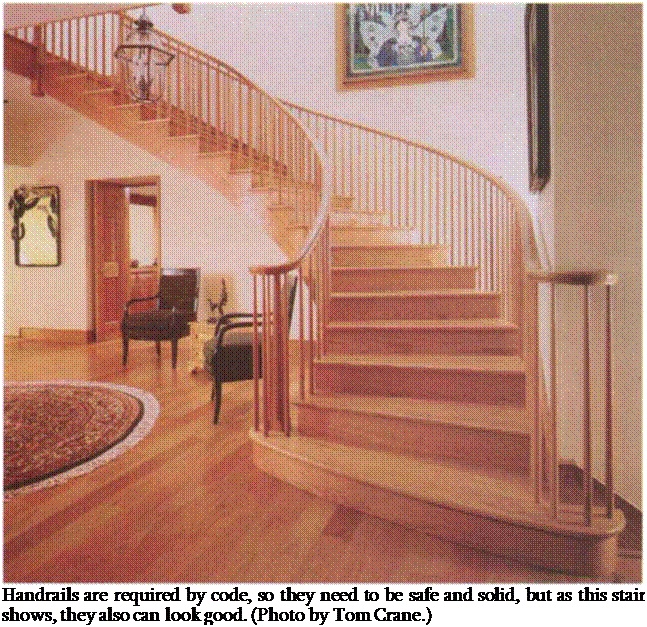
Handrails and guardrails come in many shapes, sizes, and materials. Like a seat – belt on a car, they are necessities for safety, but they can also be the highlight of a set of stairs (see the photo on the facing page). So not only do they need to look good, but they also need to be designed safely and built solidly, what­ever their style or material.

Stairs are the most dangerous part of a house, and most building codes address stair and handrail design to some extent (see the sidebar on p. 170). A safe handrail is a key part of a safe stairway, whether it is a simple rail mounted on the wall with brackets or an elaborate balustrade (a horizontal rail with evenly spaced uprights that extend down to the stair treads).

Building a simple handrail

Elaborate balustrades can be expensive to build, and their installation is outside the scope of this book. But a safe and

Подпись: Handrails are required by code, so they need to be safe and solid, but as this stair shows, they also can look good. (Photo by Tom Crane.)

sturdy handrail like the one that follows isn’t difficult to build and can do the job just as well. Depending on the particular style of stairs I’m building, I sometimes use this sturdy, easy-to-use and inexpen­sive design.

To begin, run a row of scrap 2×10 blocks up the stair slope when framing the stairs. Nail them in the walls between the studs so that their center is about 34 in. above the stair nosing. After the drywall has been hung, come back and snap a chalkline above the stairs exactly where the handrail will be placed, typi­cally between 30 in. and 38 in. above the nosing of the stair. Then drill a 5/s-in.- or 3A-in.-diameter hole near the top and bottom of the stairs and about every
3 ft. between, going through drywall and into the blocking directly along the line. Cut off б-in. pieces of 5/s-in. or 3/4-in. hardwood dowel (depending on the size of the holes) and glue them firmly in the holes.

After the walls have been finished, cut the dowels to length at about 2 Vi in. Next, get a long piece of 2×2 handrail (straight-grained Douglas fir or clear pine works well) and round the corners, sanding it smooth. Then hold the rail in position next to the dowels and mark it for drilling (a helper is handy for this step). Drill 1-in.-deep holes into the rail, apply glue, and tap the rail onto the dowels, being sure to leave it 1V2 in. away from the wall.

SOIL NAILED STRUCTURES

8.8.1 Development and General Considerations

Figure 8.52 shows a cross-section of the first soil nailed wall, which was a temporary wall built in France (1972-1973) for a railroad project. Such walls are constructed from the top down during excavation. Reinforcing bars are either inserted in drilled holes and grouted into place, or driven into place. Then a facing of cast-in-place concrete or shotcrete is installed as the work progresses.

The wall in France was built in Fontainebleau sand using a high density of short nails of two different lengths: 13 ft (4 m) for nails in the upper portion of the wall and 20 ft (6 m) for those in the lower portion. The first full-size experimental wall was constructed in Germany in 1979 using grouted nails and loaded to failure. In 1981, a prefabricated – concrete-facing soil nailed wall was used in a commercial application in France. An extensive national research project conducted in France during the years 1986-1990 resulted in a noted publication titled Recommendations Clouterre.

A soil nailed wall is constructed as an integral part of the construction of an excava­tion as illustrated in Fig. 8.53. (See Art. 8.8.7.) The soil is reinforced as the slope excavation progresses. Reinforcement generally consists of bars inserted parallel to one another and placed at a downward-sloping angle. The bars are inserted in a passive state; however, as the skin friction between the soil and the nails is mobilized, the nails are placed into tension. Figure 8.54 compares the action of soil nails and ground anchors.

The work is carried out from the top downward in increments, gradually building up a reinforced soil mass. Some type of facing is generally necessary to keep the soil from caving between the soil nails. In the case of the Fontainebleau sand (effective friction angle of 38° and some cohesion), the distance for stability of the excavation

2

FIGURE 8.52 First soil nailed wall, constructed at Versailles, France, 1972-1973. (F. Schlosser, Behavior and Design of Soil Nailing, Proceedings of Symposium on Soil and Rock Improvement Techniques,

Bangkok, 1982, with permission)

Excavate unsupported cut – 3 to 6 ft high
j

I"

STEP 4: Place initial shotcrete layer and install bearing plates and nuts

between soil nails was about 6.6 ft (2 m) with failure occurring at about 9.8 ft (3 m). The sand between the nails will slough until an “arching” action occurs within the soil. The point where this action can no longer occur because the internal friction capacity of the soil has been exceeded defines the temporary facing limit.

The concept of soil nailing has not been patented, nor is it patentable; however, numerous technologies have been patented. For soil nail walls to be cost-effective, the ground must be capable of standing unsupported while the nails and shotcrete are installed. The success of soil nail walls depends upon:

1. Selection of good applications in ground suitable for nailing

2. Ability to quickly respond to changed ground conditions

3. Use of a rational design procedure for the wall and each of its components

4. Use of good construction specifications

5. Ability of the owner and contractor to work together in a partnering concept

6. Handling of work performance on-site by knowledgeable personnel representing each of the parties, including the owner

ATYPICAL SMAs

SMA mixes have performed well in wearing courses, so it was a natural process to test them in the remaining layers of a pavement. As everybody already knows, SMA has proved to be a good material for these places. Therefore, SMA has found its way

image158

FIGURE 13.3 Thin SMA wearing course of 0/6.3 mm grading paved on the DK3 route in Poland, condition in 2006 after 13 years in operation. (Photo courtesy of Krzysztof Blazejowski.)

to intermediate layers. Also research on a special type of SMA for low-noise pave­ments is in progress in Germany.

Besides classic SMA mixes, the method of designing a strong mineral skeleton has encouraged many road engineers to carry out their own trials on new mixes. One of them is Kjellbase, though it is not a true SMA mix.

The latest atypical SMA applications are colorful mixes.

Anchor Design

Anchor design includes the selection of a feasible anchor system, estimation of anchor capacity, determination of unbonded length, and consideration of corrosion protection. In determining the feasibility of employing anchors at a particular location, considera­tions include the availability of underground easements, proximity of buried facilities to anchor locations, and the suitability of subsurface soil and rock conditions within the anchor stressing zone.

Ultimate anchor capacity per unit length may be estimated from Tables 8.9 and 8.10 for soil and rock, respectively. The values are based on straight-shaft anchors

TABLE 8.9 Ultimate Values of Load Transfer for Preliminary Design of Anchors in Soil

Soil type

Relative density or consistency*

Estimated ultimate transfer load, kips per lineal foot (N/mm)

Sand and gravel

Loose

10 (1.46)

Medium dense

15 (2.19)

Dense

20 (2.92)

Sand

Loose

7 (1.02)

Medium dense

10 (1.46)

Dense

13 (1.90)

Sand and silt

Loose

5 (0.73)

Medium dense

7 (1.02)

Dense

9 (1.31)

Silt-clay mixture with

Stiff

2 (0.29)

minimum LL, PI, and LI restrictions, or fine micaceousf sand or silt mixtures

Hard

4 (0.58)

*Values corrected for overburden pressure.

fThe presence of mica tends to increase the volume and compressibility of sand and soft deposits due to bridging action and subsequent flexibility under increased pressures.

Source: From Standard Specifications for Highway Bridges, 2002, American

Association of State Highway and Transportation Officials, Washington, D. C., with permission.

TABLE 8.10 Ultimate Values of Load Transfer for Preliminary Design of Anchors in Rock

Rock type

Estimated

ultimate transfer load, kips per lineal foot (N/mm)

Granite or basalt

50 (7.30)

Dolomitic limestone

40 (5.84)

Soft limestone

30 (4.38)

Sandstone

30 (4.38)

Slates and hard shales

25 (3.65)

Soft shales

10 (1.46)

Source: From Standard Specifications for Highway

Bridges, 2002, American Association of State Highway and Transportation Officials, Washington, D. C., with permission.

installed in small-diameter holes using a low grout pressure. Other anchor types and installation procedures may result in different anchor capacities. Allowable anchor capacity for small-diameter anchors may be estimated by multiplying the ultimate anchor capacity per unit length by the bonded (or stressing) length and dividing by a factor of safety. AASHTO suggests 2.5 for anchors in soil and 3.0 for anchors in rock.

Bearing elements for anchors must be designed so that shear stresses in the vertical wall elements and facing are within allowable limits. The capacity of each anchor should be verified as part of a stressing and testing program.

Determination of the unbonded anchor length should consider the location of the critical failure surface farthest from the wall, the minimum length required to ensure minimal loss of anchor prestress due to long-term ground movements, and the depth to adequate anchoring strata. As shown in Fig. 8.49, the unbonded (or free) anchor length should not be less than 15 ft (4.6 m) and should extend 5 ft (1.5 m) or one-fifth of the design wall height, whichever is greater, beyond the critical failure surface in the soil mass being retained by the wall. For granular soils or drained cohesive soils, the critical failure surface is typically assumed to be the active failure wedge. This wedge is defined by a plane extending upward from the base of the wall at an angle of 45° + ф72 from the horizontal, where ф’ is the effective angle of soil friction. Longer free lengths may be required for anchors in plastic soils or where critical failure sur­faces are defined by planes or discontinuities with other orientations.

Selection of anchor inclination should consider the location of suitable soil or rock strata, the presence of buried utilities or other geometric constraints, and constructibility of the anchor drill holes. AASHTO suggests that anchors be located on a minimum inclination of 10° below horizontal and the bonded zone be located a minimum depth of 15 ft (4.6 m) below the ground surface. The component of vertical load resulting from anchor inclination must be included in evaluating the end bearing and settlement of vertical wall elements.

AASHTO suggests that the minimum horizontal spacing of anchors be either 3 times the diameter of the bonded zone or 4 ft (1.2 m), whichever is larger. If small spacings are required, consideration can be given to different anchor inclinations between alter­nating anchors.

General Design Procedures for Anchored Walls

For a typical wall with two or more rows of anchors constructed from the top down, the general procedure is to (1) design for the final condition with multiple rows of anchors and (2) check the design for the various stages of construction. The required horizontal component of each anchor force can be calculated using apparent earth pressure distribu­tions such as given in Fig. 8.50. Any other applicable forces such as horizontal water pressure, surcharge, or seismic forces must be included where applicable. The anchor inclination must be considered in calculating the anchor force. The horizontal anchor spac­ing and anchor capacity must provide the required total anchor force.

Vertical wall elements must be designed to resist all applicable forces such as hori­zontal earth pressure, surcharge, water pressure, and anchor and seismic loadings, as well as the vertical component of earth pressure due to wall friction and the vertical component of anchor loads and any other vertical loads. In the analysis, supports may be assumed at each anchor location and at the bottom if the vertical element extends below the bottom of the wall.

All components should be checked for the various earth pressure distributions and other loading conditions that may exist during construction.

Structure Dimensions and External Stability

The design of anchored walls involves a determination of several factors. Included are the size, spacing, and depth of embedment of vertical wall elements and facing; the type, capacity, spacing, depth, inclination, and corrosion protection of anchors; and the struc­tural capacity and stability of the wall, wall foundation, and surrounding soil mass for all intermediate and final stages of construction. The bearing capacity and settlement of vertical wall elements under the action of the vertical component of the anchor forces and other vertical loads must also be evaluated.

AASHTO provides the following guidance:

For walls supported in or through soft clays with Su < 0.3y’H, continuous vertical ele­ments extending well below the exposed base of the wall may be required to prevent heave in front of the wall. Otherwise, the vertical elements are embedded several feet as required for stability or end bearing. (Where significant embedment of the wall is required to prevent bottom heave, the lowest section of wall below the lowest row of anchors must be designed to resist the moment induced by the pressure acting between the lowest row of anchors and the base of the exposed wall, and the force Pb = 0.7(yHBe — 1.4cH — ^cBe) acting at the mid-height of the embedded depth of the wall.)

In the above, the following definitions apply:

Be = width of excavation perpendicular to wall c = cohesion of soil H = design wall height

Su = undrained shear strength of cohesive soil у = soil unit weight y’ = effective unit weight of soil

The end of the Han and the last great hydraulic projects

Reconstruction efforts mark the beginning of the period of the “latter” Han. The Bian canal had greatly suffered from inundations, and the repair works were directed by an engineer called Wang Ching. In 70 AD the Emperor Mingdi inspects this work:

“Since the dike ruptures at the outlet of the Bian canal, more than sixty years have passed. [….] The original emplacements of the gates have been lost in the middle of the river. Large expanses of water have formed, to the point that one could no longer recognize the original banklines. But now, the dikes have been reconstructed and the canal has been repaired, the flow stopped, and gates put back into place. The river (Yellow) and the canal (Bian) flow sep­arately and have returned to the original beds. Because of this, we have sacrificed the most beautiful jade and the purest animals to the spirit of the river.”[420]

About 80 AD the Shaobei (today the Afentang dam) was also rebuilt; it dated from

the period of springs and autumns.

An agricultural crisis afflicts the empire of the “latter” Han from 170 AD. Major new floods occur on the lower course of the Yellow River. The desperation of the affect­ed population once again creates a fertile ground for agitators; a large revolt is organized in 185 by the secret society Yellow Turbans. Although the revolt is quashed the dynasty does not survive it, being abolished in 220 AD.

The result of this collapse is a schism of the empire into three kingdoms, during which new hydraulic projects are undertaken. Avast irrigation system is put into serv­ice in 189 in the region of the ancient dam Shaobei, with numerous weirs built on small rivers. New transport canals linking the Jiang and the Hutuo in the north are built to sup­port the offensive of the northern sovereign Cao Cao against his rival Yuan Shao in 204 AD. South of the Yangtze, dam-reservoirs are still being built in the 4th century AD; the Han canal, linking the Huai to the Yangtze, is also rebuilt during this period. These new canals already prefigure the future Grand Canal, whose construction accompanies the rebuilding of the empire. But it will be three long centuries, the chaotic period of the Chinese middle ages, before this construction begins.

Open-Graded Drainage Layers (OGDLs)

According to Huang (2003) the placement of a drainage layer directly under the asphalt or concrete pavement surface is preferable, because the water in the pavement, either percolating through cracks or entering from the sides, is quickly allowed to move to a lower level from where it can easily be drained. No pore pressures can develop because of the high permeability and rapid dissipation prop­erties of the OGDL eliminating any chance of pumping occurring. Furthermore, it eliminates the final, negative, effects of water or frost. A properly designed and con­structed permeable granular base layer may have a similar structural performance as a conventional base. However, OGDLs have a number of disadvantages:

• the deficiency of fines in the drainage layer may cause stability problems. They are difficult to compact into a stable foundation on which higher pavement lay­ers can be constructed. Perhaps even more problematic is the trafficking of the OGDL by the construction plant that will lay the next pavement layer;

• the water in the sub-base cannot drain readily into the drainage layer;

• if the outlet becomes blocked the drainage layer becomes a reservoir for pore water that can develop pressure pulses under passing traffic thereby causing ero­sion and loss of bearing capacity. This can be a particular problem under jointed pavements where ingress of water along joints may be rather large once joint sealants have failed.

A recent study in Finland showed that more open-graded sub-base is a satisfac­tory means of reducing the moisture content of a granular base course, but that such a sub-base should not be used beneath an open-graded base course due to stability issues.

Typically, open-graded unbound granular materials are used as permeable layers, however the use of cement or asphalt treated permeable bases can add some extra strength and stability to the drainage layer (and, hence, the pavement) if needed. The resulting material is some kind of buried “no-fines” concrete or porous asphalt. Normal OGDLs are relatively expensive to source, due to the wastage of the fine fraction, and expensive to compact due to the stability issue. Treatment only adds to this.

Table 13.2 Example of gradation of unbound granular permeable bases in Spain

Sieve size (mm) 25 20 8 4 2 1 0.500 0.250 0.063

Passing (% by mass) 100 65-100 30-58 14-37 0-15 0-10 0-6 0-4 0-2

Although authors differ over the precise value, pavement layers can be consid­ered as permeable when their coefficient of permeability exceeds approximately 10-5 m/s. Therefore, many of the conventional dense-graded unbound granular layers cannot be considered as permeable. Table 13.2, shows a typical grading of permeable granular layers used in Spain, where material passing the 1 mm size sieve is limited to 10% (by mass). Since sometimes segregation problems have been detected when pavers are used to lay the layer down, a uniformity coefficient, Cu, less than 4 is required. In addition, in order to get enough stability during the con­struction of the layer above, the permeable base must mostly be made of crushed aggregate.

Illinois experimented with the use of thin treated OGDLs (7.5-15 cm thick) beneath both concrete and asphalt surfaced pavements during the late 1980’s and early 1990’s (Winkelman, 2004). Four projects were constructed to monitor the effectiveness of the drainage layer and the performance of the pavement. Five ad­ditional projects were constructed based on the early performance of the moni­tored projects. However, continued monitoring of the initial projects, and additional projects, indicated two of the pavements were quickly deteriorating. Surface pave­ment distress, severe lane to shoulder differential settlement, and high pavement deflections for these two projects indicated a failure of the pavement structure.

The immediate response was to stop using OGDLs, although the non-failing pavements built over OGDLs were not removed. Six of the projects were monitored through from construction until 2003 to ascertain the longer term performance of these pavements and to see whether the OGDL had been beneficial. Some contained cement-treated OGDLs, some asphalt-treated OGDLs.

It was concluded that:

i) The use of an OGDL is more expensive than the use of a standard stabilised base material or lime modified soil;

ii) Some limited benefit due to drainage may be achieved, particularly early dur­ing the life of the pavement. However, the longer term performance of the monitored pavements was not much better than that typical for other pave­ments in the area built without OGDLs;

iii) The intrusion of fines from the subgrade and the aggregate separation layer into the OGDL resulted in settlement, faulting, and eventually premature fail­ure of the pavement, therefore, the use of a geotextile fabric or dense graded aggregate filter under the OGDL to prevent the intrusion of subgrade fines is recommended;

iv) The benefits of using cement-treated OGDLs over asphalt-treated OGDLs, or vice versa, could not clearly be determined;

v) For continuously reinforced concrete pavements, the limited benefits of using an OGDL do not outweigh the increased costs, construction difficulties and maintenance requirements;

vi) Segregation is problematic during construction and careful use of plant is needed to minimize it; and

vii) Careful consideration should be given to subgrade soil analysis, topography and surface drainage, and pavement type. OGDLs are not suitable for all situ­ations.

Most of the pavements were quite heavily trafficked and it may be that different findings would have been obtained on more lightly trafficked pavements.

On Priming Painted Surfaces

Primers bond to substrates and provide a sta­ble base for finish coats. Thus it’s wise to prime previously painted surfaces in the following situations:

► You’re switching paint types—say, apply­ing latex over oil-based.

► The old paint is flaking, chalking, stained, or otherwise in bad shape.

► The old paint is glossy and thus would prevent the new paint from adhering well.

Before applying primer, scrape, fill, sand, wash, and rinse the surface and allow it to dry thoroughly.

In general, like bonds best to like. That is, latex paint bonds best to latex primer, oil-based to oil-based. But a quality acrylic latex primer is a good all-purpose choice because it bonds well and suppresses water stains, crayon marks, smoke, rust, and creosote. However, if you get severe bleed-through, switch to an oil-based sealer-primer instead.

Stickability test

Here’s how to test old paint before selecting a new paint, to ensure that the new paint will stick:

► Bend a paint chip that’s coming off.

If it cracks, it’s oil-based; if it flexes, it’s latex.

► Duct-tape a wet sponge to the wall; then wait 15 minutes. If there’s paint on the sponge or you can rub any off the wall, it’s latex.

► Put a few drops of latex solvent such as Goof-Off® on a painted windowsill; if the paint bubbles, it’s latex.

sashes off-site or in an on-site "stripping room” will isolate a major source of lead dust. Old trim can be relatively brittle and tedious to remove and reattach, so strip it in place. Finally, shut off the central heating system during demolition and lead-abatement so it won’t recirculate lead dust throughout the house

Contain and clean up the mess. Use sheet plastic to isolate and contain the mess. Duct tape it across door openings to seal off work areas from living space, and cover floors with a double layer of 6-mil plastic duct taped to baseboards to keep it in place. If two layers of plastic prove too slip­pery, protect the floor with rosin paper or heavy cardboard instead, and cover that with plastic.

The top layer of plastic will catch the debris and dust, so roll it up and discard it when demolition is done.

Outdoors, sheet plastic is also indispensable for lead abatement: Run a drop cloth of 6-mil plastic at least 8 ft. out from the building, to catch paint chips and the like. Duct-tape it to the foundation so it will stay put. Because it’s not feasible to physically isolate the outside of a building, you’ll need power tools with vacuum attachments to capture lead dust generated by a sander or power scraper. A HEPA-filtered vacuum will capture about 95 percent of the dust; the plastic drop cloth needs to catch the rest.

After stripping and vacuuming interior or exterior surfaces, hand wash contaminated areas to remove any residual lead dust. Don’t use a power washer, which can soak the walls and scatter the debris you’ve worked so hard to con­tain. Rather, use a three-bucket clean-up: (1) Spray on detergent, using either a spray bottle or a gardener’s pump sprayer before scrubbing the surface with a dampened sponge or a sponge mop. (2) Squeeze out the dirty water into the first bucket before dipping the sponge in a second rinse bucket and squeezing it again. (3) Dip a mop into a third bucket of clean water, squeeze, and you’re ready to repeat the process. Change the water in all three buckets often. Follow the NEPA’s NLIC suggestions for disposing of waste water.

Painting the Interior

If you see water stains, widespread peeling, mold, or large cracks that suggest structural movement, attend to the underlying causes first.

GETTING READY TO PAINT

When painting interiors, it’s best to move the fur­niture out. If that’s not possible, group it in the center of the room and cover it with a plastic tarp. Remove drapes, wall hangings, and mount-

Подпись: LINGERING PAINTimage906Подпись: As paint dries, it outgasses (gives off gases), releasing water vapor or mineral spirits and additives into the air. The warmer the room and the better the ventilation, the sooner the smells will dissipate. Labels on paint cans indicate drying times. Typically, in a room that is 60°F or warmer, acrylic latexes will be dry enough to recoat in 2 hours to 4 hours. Oil-based paints can be recoated in 24 hours. However, odors may linger because the paints need longer to cure: 8 days to 10 days for latex, 28 days to 30 days for oil-based paints.ing hardware, and fill holes. О Turn off electric power to the room—use a voltage tester to be sure it’s off—and remove the cover plates of electrical outlets and switches. Light fixtures or hardware left in place should be masked off or wrapped in plastic. Finally, cover the floor with canvas drop cloths—plastic is too slippery to work on.
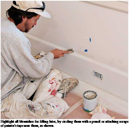
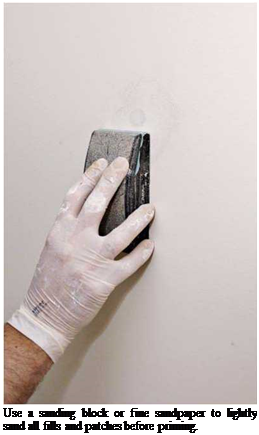
Previously painted surfaces don’t need much preparation if they are intact: Sand lightly with 150-grit sandpaper or a sanding block. If paint’s flaking or loose, remove it with a paint scraper or spackling knife. Then sand rough paint edges with 120-grit to 150-grit sandpaper. Use spackling compound to fill holes, and sand it when dry. Apply a bead of paintable caulk (acrylic latex) to fill gaps where the trim meets walls, smoothing it with a moist finger. Caulking makes the finished paint look much better.

Before you apply paint, lightly sand all painted surfaces so successive coats will adhere better. After sanding, dry mop or vacuum surfaces to remove dust. Then sponge wash them with a mild detergent solution and rinse with clear water. If the walls are especially greasy (kitchen walls, for example), use a more aggressive cleaner like TSP (trisodium phosphate). After rinsing, allow walls to dry thoroughly before painting.

A good test of dryness is to check whether a piece of transparent tape will stick or not.

Unpainted drywall and plaster must always be primed. You can prime drywall as soon as the final, top coat of joint compound has dried and has been sanded. Some pros still prefer an oil – based primer for drywall, but today’s acrylic latexes seal as well and are far easier to clean up.

Подпись: Highlight all blemishes for filling later, by circling them with a pencil or attaching scraps of painter's tape near them, as shown. Подпись: Use a sanding block or fine sandpaper to lightly sand all fills and patches before priming.

Plaster surfaces must be cured thoroughly before painting. Although latex primers can be applied as soon as the plaster is dry to the touch, it’s better to wait 3 weeks to 4 weeks. Latex paint allows some migration of moisture, so plaster can continue to "breathe off’ water vapor. Restorationists familiar with plaster recommend

diluting latex primer 15 percent with water so its coating is thinner and even more permeable.

Oil-based paints are another story. Because the alkali in plaster can remain "hot” for up to 3 months, wait that long before using oil-based paints. Otherwise, free alkali in the plaster will attack the paint. Akaline-resistant primers for­mulated for new plaster may shorten your wait somewhat, but they must be special ordered.

But before ordering, make sure that primer will be compatible with your final-coat paint.

PAINTING CEILINGS AND WALLS

Before painting, read this chapter’s earlier sec­tions on equipment (especially respirator masks), safety concerns, and painting basics. All offer tips that can save you hours and keep you safe.