Construction Considerations for Soil Nailed Walls

The construction sequence is typically to excavate, nail, and shotcrete the face in increments from the top down. Figure 8.56 shows a schematic of a sequence for underpass widening. Where face stability is a concern, a flashcoat of shotcrete may be applied before nail installation. The most common method of nail installation in

FIGURE 8.56 Construction sequence for soil nailed wall used in widening of underpass. (From Oregon Department of Transportation, with permission)

all nail layers

STEP 7: Place second structural application to full height and architectural finish

FIGURE 8.56 (Continued)

Europe, as in the United States, is the drill-and-grout method. Most commonly, the steel tendon is installed prior to grouting, although this sequence is sometimes reversed. In France, however, very significant use is also made of driven nails without grouting. Other specialty techniques for installing nails include jet grout nailing (France), driven nails with an oversize head and subsequent grouting of the annulus (Germany), and compressed-air explosive injection of nails (United Kingdom).

Small hydraulic, track-mounted drill rigs of the rotary-percussive type are most com­monly used to install nails. These rigs can work in relatively confined surroundings and are therefore compatible with many of the constraints associated with crowded urban

environments. Open-hole drilling methods are predominant, with cased-hole methods used in particularly difficult ground conditions. The most common grouting method used with open-hole drilling is the low-pressure tremie method. Where extensive use of casing is required, alternative methods of construction are often more cost-competitive.

Steel tendons typically used for drill-and-grout soil nails usually consist of /4- to 2-in­diameter (20- to 50-mm) bars with a yield strength in the range of 60 to 70 kips/in2 (420 to 500 N/mm2). These steels exhibit ductile behavior under bending action. The driven nails used commonly in France are typically steel angle sections, which show better ability to deal with subsurface obstructions such as cobbles and small boulders than do circular steel sections.

Drainage is a critical aspect of soil nail wall construction. Face drainage is virtually always used with permanent walls, and very commonly used with temporary walls. Face drainage usually consists of synthetic drainage elements placed between the shotcrete and the retained soil, and may be typically 8- to 12-in-wide (200- to 300-mm) synthetic strips or perforated pipes. Depending on the site groundwater conditions, face drainage may be supplemented with weep holes through the facing and longer horizontal perforated drain pipes. Control of surface water is also an important element of the drainage system.

Temporary soil nail wall facings generally consist of shotcrete 3 to 4 in (80 to 100 mm) thick and a single layer of wire mesh. Permanent shotcrete walls 6 to 10 in (150 to 250 mm) thick are very common in Germany, and these walls typically include a second layer of wire mesh. For architectural reasons, permanent walls of precast panels and cast-in­place concrete are also commonly used in France and Germany.

Testing and monitoring during construction are an important aspect of soil nail wall construction in Europe. Nail bond testing is almost universally performed, to confirm the assumptions made during design or to enable redesign in the event that the design assumptions cannot be realized. For relatively homogeneous sites, typically 3 to 5 percent of the nails will be tested, depending on the size of the job. Testing is also undertaken whenever changed geologic or construction conditions occur. Wall performance moni­toring usually consists of measuring horizontal wall movements during construction. Some contractors make more use of inclinometers for displacement monitoring. Maximum horizontal displacements are typically in the range of 0.1 to 0.3 percent of the height of the wall, depending on ground conditions. Strain gauging of nails, together with the use of load cells at the nail head, is usually reserved for experimental walls.

The level of quality assurance and control monitoring varies significantly. In Germany, for example, the QA-QC inspector might be on the job from 10 percent to full time.

Overall, soil nail wall performance in Europe has been very good. Problems during construction have typically been associated with encountering loose fill, granular soil with no apparent cohesion, water, and constructed obstructions such as utility trenches. Other problems have been associated with a contractor’s failing to construct the wall in accordance with the plans and specifications (e. g., eliminating nails, overexcavation of lifts). Frost action on fully bonded nails has also resulted in development of very large loads near the head of the nail, where no insulating protection has been provided in the wall design.

Design of Soil Nailed Retaining Structures

The stability of a soil nailed structure relies on (1) transfer of resisting tensile forces generated in the inclusions in the active zone into the ground in the resistant zone, through friction or adhesion mobilized at the soil-nail interface, and (2) passive resistance developed against the face of the nail. Ground nailing using closely spaced inclusions produces a composite coherent material. As shown in Fig. 8.54, the tensile forces gen­erated in the nails are considerably greater than those transmitted to the facing.

The design procedure for a nailed retaining structure includes (1) estimation of nail forces and location of the potential sliding surface, (2) selection of the reinforcement type, cross-sectional area, length, inclination, and spacing, and (3) verification that stability is maintained during and after excavation with an adequate factor of safety. Methods for determining tensile, bending, and shear stresses in the nails are given by FHWA based on a limit equilibrium analysis.

The majority of soil nailed retaining structures constructed in France are based on two distinct technologies: (1) the method of Hurpin, with nails driven into the ground on close spacing, i. e., vertical and horizontal spacing equal to or less than 3 ft (1 m), and (2) widely spaced grouted nails. With the method of Hurpin, the nails (generally reinforcing bars) are relatively short and are driven into the ground by percussion or vibratory methods. The relatively high nail density permits thinner wall facings. In walls with widely spaced nails, the nails are generally longer. Typical data for soil nailed walls with a vertical facing and a horizontal earth pressure are shown in Table 8.11. The “nailing density” listed in Table 8.11 is a dimensionless parameter representing soil nails placed in a uniform pattern. It is defined as

(8.25) where T = ultimate tensile force that can be mobilized at head of nail

Г

Sh = horizontal spacing between nails Sv = vertical spacing between nails L = length of nails у = total unit weight of soil

This parameter represents the maximum tensile force in a nail as it relates to the weight of the soil reinforced with a chosen grid spacing.

A full set of preliminary design charts is included in the FHWA translation of Recommendations Clouterre, 1991. Diagrams for an angle of installation of the nails of i = 20° are shown in Fig. 8.55 for illustration.

Figure 8.55 provides a preliminary chart for a soil nailed wall. It seeks to define in approximate terms the lengths, spacings, and resistance values of the nails to ensure

TABLE 8.11 Typical Characteristics of Soil Nailed Walls with Vertical Facing and Horizontal Earth Pressure

Nails at close centers (method of Hurpin)

Widely spaced nails

Length of nails

0.5 to 0.7H

0.8 to 1.2H

Number of nails per m2

1 to 2

0.15 to 0.4

of facing Perimeter of nail

150 to 200 mm

200 to 600 mm

(6 to 8 in)

(8 to 24 in)

Tensile strength of

120 to 200 kN

100 to 600 kN

reinforcing bar (nail)

(34 to 45 kips)

(22 to 135 kips)

Nailing density

0.4 to 1.5

0.13 to 0.6

Source: From Recommendations Clouterre, French National Research, 1991,

(English translation by Federal Highway Administration, 1993), with permission.

FIGURE 8.55 Preliminary design charts for soil nailed walls. (From Recommendations Clouterre, French National Research, 1991, trans­lation by Federal Highway Administration, 1993, with permission)

internal and external stability. It may be used in an early evaluation stage based on macro assumptions such as homogeneous soil, identical and evenly spaced loads in the nails, and pure tension in the nails; the bending stiffness of the nails is neglected, regardless of the angle of incidence of the potential failure surface. This approach is based on the classic method of vertical slices with circular potential failure surfaces. The charts are based on a system of coordinates that characterize the shear resistance of the soil.

c 20

N = ————— = —————————- = 0.10 tan ф = tan 35° = 0.70

7H 20 X 10 v

Draw a line from the origin O to M. The safety factor F is the ratio OM/OA. Therefore, for a safety factor of 3/2, locate point A two-thirds of the distance along the line OM. Interpolation gives the required nailing density d as 0.33. Thus:

TL

7—

0. 33 X 20 X 0.8 X 10 = 52.8 kPa

Thus, for a nail tensile force TL, the spacings Sh and Sv can be determined. The result from the chart should be generally conservative and used only for preliminary evaluation.

The final design for stability of a soil nailed wall is analyzed either by calculating the deformations or by using limit equilibrium design. The first method uses finite ele­ment calculation and has not been refined to the point where there is an “acceptable” procedure. In Europe to date, there has been considerable diversity in some details among the various design approaches, both within and across national boundaries. A most significant factor is the postulated mechanism by which nails are considered to reinforce a soil mass. For nails installed nearly parallel to the direction of maximum soil tensile strain (e. g., near-horizontal nails and a near-vertical excavation face), the prevailing opinion is that the reinforcing action is predominantly related to tensile loading within the nails. Under service load conditions, the contribution of shear or bending is considered negligible. As failure conditions are approached, the contribution of shear or bending action is more significant but still small. From a practical point of view, however, it is recognized that the soil nails should exhibit ductile behavior in response to bending in order to minimize the potential for sudden failures related to brittleness. Where reinforcing elements are used as dowels and are oriented nearly perpendicular to the direction of maximum shear strain, the shearing, bending, and tensile action of the reinforcement should be considered.

All design methods are based on concepts of limiting equilibrium or ultimate limit states. Various types of potential slip surface are considered, including circular, log spiral, and bilinear wedge. In general, each of the methods appears to provide a satis­factory representation for design purposes. Consistent with the above, most design computer codes consider only the tensile action of the nails, but some also permit con­sideration of the shear or bending action of the nails. Almost all of the design methods do not explicitly consider the potential for pullout of the reinforcing nails within the active block between the facing and the slip surface. It is implicitly assumed that the nail – soil adhesion within this zone, together with the structural capacity of the facing, will be sufficient to prevent this type of failure. Some design approaches offer strict guide­lines for the required structural wall capacity to prevent such active-zone failures, but others appear to rely on experience and do not directly address this issue.

On the basis of the overall reinforcing requirements determined from the limiting equilibrium design calculations, the reinforcing steel is empirically proportioned. In general, designers use nails of uniform length and cross-sectional area, on a uni­form spacing. For drilled and grouted nails, the nail spacing is typically in the 3- to 6-ft (1- to 2-m) range. For driven nails, much higher densities (typically 1.5 to 2 nails per
square meter) are used. The nail lengths are typically in the range of 60 to 80 percent of the height of the wall, but may be shorter in very competent rocklike materials and longer for heavy surface surcharge or high seismic or other operational loading.

As noted above, facing design requirements are empirically determined using a variety of techniques. German practice requires the use of a uniform facing pressure equivalent to 75 to 85 percent of the active Coulomb loading. The Clouterre recom­mendations require designing the facing and connectors to support between 60 and 100 percent of the maximum nail loading (for both ultimate and serviceability limit states), depending on the nail spacing.

Wall Drainage Systems

Almost all shotcrete failures in slope stabilization applications have resulted from

inadequate drainage. Therefore, drainage is a critical design and construction element.

Drainage from behind the shotcrete face can be provided by the following methods:

1. Surface interceptor ditch. Excavate a shallow ditch along the crest of the excavation to lead away surface water. Drainage gutters or lined ditches are recommended immediately behind the top of the wall.

2. Prefab geotextile drains. Place 12-in-wide (300-mm) prefabricated geotextile drain strips (Miradrain 6000, Amerdrain 200, etc.) vertically prior to applying the shotcrete. Typical spacings are the same as the horizontal nail spacing. Extend the drain mats down the full height of the excavation and discharge into a collector pipe at the base.

3. Weep holes and horizontal drains. Install 2-in-diameter (50-mm) PVC pipe weep holes on approximately 10-ft (3-m) centers through the shotcrete face where heavier seepage is encountered. Plug the pipe temporarily when shotcrete is applied. Longer PVC horizontal drain pipes can also be installed in heavy seepage areas.

8.8.3 Wall Facing Systems

Temporary walls are typically left with a rough shotcrete face—“gun” finish—with weep holes and protruding nail heads. For permanent walls, where the rough finish is aesthetically unacceptable, the following face options are available:

1. Separate fascia wall. As an alternative to the exposed shotcrete finish, the shotcrete can be covered with a separate concrete fascia wall, either cast in place (CIP) or constructed of precast panels. The CIP section is typically a minimum of 6 to 8 in (150 to 200 mm) thick. Precast face panels can be smaller modular panels or full – height fascia panels such as those used to cover permanent slurry walls. A disadvantage of the smaller modular face panels is difficulty of attaching the face panels to the nail heads and some proprietary patent restrictions. A disadvantage of full-height precast panels is that, because of practical constructibility weight and handling limitations, their use is limited to wall heights less than 25 ft (8 m).

2. Permanent exposed shotcrete facing. Present technology for shotcrete place­ment is such that the final shotcrete layer can be controlled to close tolerances, and with nominal hand finishing, an appearance similar to a CIP wall can be obtained (if desired). The shotcrete, whether left in the natural gun finish or hand-textured, can also be colored either by adding coloring agent to the mix or by applying a pigmented sealer or stain over the shotcrete surface. Only experienced, well-qualified structural shotcrete specialty contractors should place and finish the permanent structural shot – crete. “Wet-mix” shotcrete should be specified instead of dry-mix because good quality control is easier with wet-mix. Also, wet-mix shotcrete can be air-entrained for improved freeze-thaw durability, whereas dry-mix cannot.

Filter Criteria

Aggregates and geotextiles employed in drainage systems have to operate next to soil or aggregate that surrounds them. To achieve good performance, they must re­main permeable, retain the surrounding ground or aggregate in place and not clog. These requirements are met by defining specific performance criteria. The first of these is the non-sedimentation criteria, which is usually provided by aggregates with no plasticity and a limited amount of fines (usually no more than 5%).

The following filter criteria should be fulfilled:

• F15 (filter material)/D85 (soil) < 5

• F15 (filter material)AD15 (soil) > 5

• F50 (filter material)/D50 (soil) < 25 where the number, n, following F is the size of the sieve through which n% of a filter soil will pass and the number, m, following D is the size of the sieve through which m% will pass of the soil being drained. This terminology was introduced in Chapter 2, Section 2.4.1.

Typically, literature about geosynthetics also defines the following filter crite­ria (e. g. Bergado et al. (1996) who give a long list of references on the subject, Christopher & Holtz (1985) or Koerner (2005)). Firstly, to ensure that the filter holds the soil in place and doesn’t let it through – the “retention criterion” – the following requirements are, typically, set:

• for fine-grained and erodible soils

• for fine-grained cohesive soils

• for problematic (gap-graded) soils

• for coarse-grained and well graded soils where O90 is the effective opening size – 90% of the openings in the geosynthetic are smaller than this value, and Cu is the Uniformity Coefficient (see Chapter 2, Eq. 2.4).

Next, to ensure that particles of soil don’t enter the filter’s pores and clog it – the “clogging criterion” – the following requirements are, typically, set: • O90 < 5D90 although, for cohesive, soils O90/D90 may be larger.

There will usually be a “permeability criterion”, too, as the geosynthetic should remain at least as permeable as the protected soil throughout its lifetime. For this reason, the permeability of the geosynthetic should be N times greater than that of the soil it is filtering at the outset, where N typically varies between 10 and 100. To achieve this criteria such as the following may be set if permeability values are not obtainable:

• for fine-grained cohesive soils O90 > 0.05 mm

• for coarse-grained and well graded soils O90 > DJ5 and O90 > 0.05 mm.

Where a filter is provided between the soil and a grooved, slotted or perforated medium such as a porous plastic pipe, the relationship between the dimension of the filter material and the grooves or the tube perforation size should be as follows:

• F85 > 1.2 times the grooves’ width, or

• F85 > 2 times the perforations’ diameter.

Where it is difficult to know the best design solution, drains can be filled with aggregate wrapped in a geotextile which has a coefficient of permeability 10 times more than the surrounding soil’s coefficient of permeability.

The characteristics required of geotextiles and geotextile-related products for use in drainage systems is contained in European Standard EN 13252 (2000). InEurope, all geosynthetics used in drainage systems should be CE marked.

Building codes governing handrails and guardrails

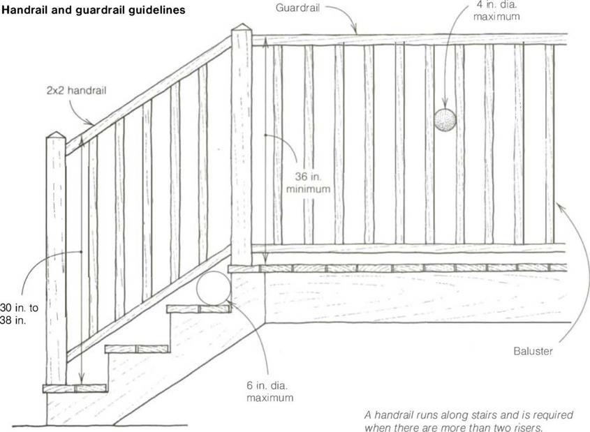
• Every stair over three risers needs at least one handrail.

• Stairs 44 in. wide need a handrail on each side.

• Locate the handrail 30 in. to 38 in. vertically off the nose of the stair tread.

• Diameter of the railing must be 1 V2 in. to 2 in. for easy grasp.

• Leave a 11/г-іп. gap between the rail and wall on enclosed stairs.

• Extend the rail the full length of the stairs.

• Minimum guardrail height on landings or decks must be from 36 in. to 42 in.

• Balusters (uprights between handrail and treads or landings) must run vertically so that children can’t climb on them.

• Spacing between balusters should not be more than 4 in. so that children can’t squeeze through.

Building codes governing handrails and guardrails

Building codes governing handrails and guardrails

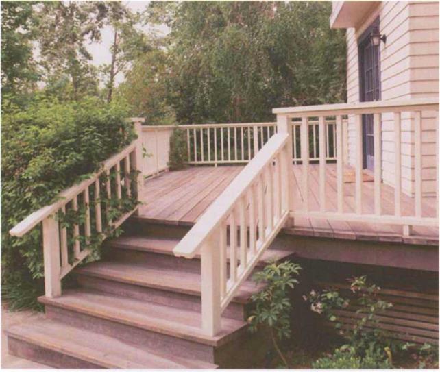
A simple outdoor handrail or guardrail for stairs and decks can be made of naturally rot-resistant wood, such as cedar or redwood, or pressure-treated wood. (Photo by Dean Della Ventura.)


Building an exterior guardrail

Often, a handrail becomes a guardrail, enclosing an upper area like a landing or a deck. Like stairs and handrails, guardrails can be built using numerous designs and materials, but because they protect people from falling, they need to be safe and solidly built.

A guardrail design that I’ve often used for decks and balconies has a simple but classic look and can easily be modified—with fancy balusters, for example—for different situations (see the photo above). Although I prefer to work with cedar or redwood for these structures, here on the wet Oregon coast, we frequently use pressure – treated wood.

First, set 4×4 vertical posts every 8 ft. or so in the floor structure to hold the guardrail, notching and bolting these posts securely. Cut the posts 39 in. long, then cut and attach 2x4s laid flat about 3 in. above the floor deck between these posts. After nailing another 2×4 flat on top of the posts, cut 2×2 balus­ters at 40У2 in., predrill them, and screw them vertically to the 2x4s with 3-in. deck screws. Plan your spacing so that there is no more than a 4-in. gap between each baluster.

Once the balusters are in place, cut and attach a 2×6 flat on top of the upper 2×4, which makes the total railing height 42 in. If you attach the upper 2×6 rail to the 2×4 from the underside, there won’t be any penetrations to allow moisture into the rail, and it will look better.

STEP3 Install the Window and Door Casings

If you’ve installed prehung doors with the cas­ing (trim) attached, then some of your trim – work has already been done. If not, then the time to trim the windows and doors is now. Remember: Accuracy is critical for good finish work. All joints between pieces of wood should be tight, with no space showing.

Doing a good job depends on having the right tools, measuring carefully, and using a few finish carpentry tricks. Make sure you have a good chopsaw that is fitted with a finish-cutting blade. A nailer is a tremendous time-saver when installing trim, and it ensures that installed pieces won’t be marred by ham­mer blows (see the photo above). However, you can still do the job the old-fashioned way if you have to—with a hammer, finish nails, and a nail set. If you cut a joint that doesn’t fit well, cut it again, and make it right. Don’t rely on putty or caulk to fill any but the smallest of gaps. Caulk shrinks as it dries, so relying on it to hide shoddy work isn’t a good solution.

Install windowsills

When trimming around a window, it’s fine to cover the trimmers and header with drywall,
as described in chapter 9. But don’t use dry – wall for the sill; it won’t hold up. Besides, a wood sill adds a bit of warmth and style to a house. It looks even nicer when you surround the window with a wood jamb and casing.

Подпись: Helping HandПодпись: Practice using a chopsaw. For better results when cutting trim on a chopsaw, make some practice cuts in scrap material. Practice making the same miter, square, or beveled cuts you'll be making when installing trim. Test the results with a combination square to make sure your square and 45-degree cuts are accurate.WOOD AND MDF SILLS HAVE DIFFERENT ADVANTAGES. Standard, %-in.-thick stock works fine as a sill, but I think thicker stock— 1 in. or even I’/ in.—looks better. If you want to see natural wood and your budget allows it, trim with oak, pine, or spruce, and seal it with clear finish. If you prefer a painted finish or your budget is very tight, choose medium- density fiberboard (MDF). Like wood, MDF can be shaped into many styles of trim. It cuts much like wood does and, once painted, looks like solid wood but without an evident grain pattern. Just remember: MDF must be kept away from moisture, which can cause it to swell and come apart.

CUT THE SILL TO SIZE. When a window is trimmed on the sides with drywall, each end of the sill should extend about V/ in. beyond the drywall corner on the side of the window opening. When a window is trimmed with wood casing, take into account the width of the window opening, plus the width of the wood casing on both sides, plus 2 in., then cut the sill to that length. That way, the side cas­ings rest on the sill and the sill extends 1 in. beyond the casing on each side. A sill should be wide enough to cover the rough sill and extend at least VA in. from the wall. You can vary the projection distance to suit your

needs. The sill I have by my writing desk extends УА in. beyond the wall; its wide enough to hold a book or a vase.

*

NOTCH THE SILL. Once the sill is cut to length, cut a notch in from each corner to leave what’s known as a horn for the casing to rest on (see the illustration at left). For the depth of the notch, measure in from the edge of the drywall to the window frame and mark your cut lines on the sill. Or you can hold the sill at the window opening and mark the cut lines with a combination square. That will give you an accurate cut line, even if the jamb sides are not square.

Whether you make the cut with a handsaw or a jigsaw, clamp the workpiece securely to a sawhorse or workbench so that it will be easier to make exact cuts. Remember that this is fin­ish work. Take your time and do it accurately. The sill should fit snugly against the window frame. If there are small gaps between the sill and the drywall on the sides, fill them with paintable caulk.

Don’t leave the front edges and corners of the sill sharp. Instead, use a block plane to make a bevel or chamfer on the edges, or round them over a bit with sandpaper. This will improve the look and feel of the sill. It also makes the trim less hazardous to small children. Secure the finish sill to the rough sill with construction adhesive and drive two 6d or 8d nails at each end.

Once the sill is in place, cover the trimmers and header with M-in.-thick stock, as shown in the illustration above. The side (and head) jambs are cut flush with the plane of the wall, set on the wood sill, and nailed in place. The head jamb fits snugly between the two side jambs. Make sure all your cuts are square and fit tightly together. Nail them in place with 6d finish nails.

Low Noise SMA

Earlier, common practice has designated porous mixtures as the most effective way of reducing traffic noise. One – or two-layer pavements have been used, while the latter ones generally are a more effective option. However, that is an expensive solu­tion. On the other hand, it has been found (von Bochove and Hamzah, 2008) that gap-graded mixes composed in accordance with the SMA concept—with an air void content of 9-16% (v/v)—provide a worthwhile alternative to porous asphalt in urban areas. They are marked by a higher resistance to the loads occurring in urban traf­fic conditions, a longer service life, and good noise reduction properties (up to -5 dB[A]). At the same time, the authors have added that such a mixture cannot be a conventional SMA, but it has to distinguish itself by a significant gap grading and a strong skeleton of coarse particles.

The concept of a “silent” SMA (SMA LA), which is being developed in Germany, is an example of such a solution. Some test sections on roads in Bavaria (Germany) made of SMA LA mixtures 0/5 and 0/8 have been described (Gartner et al., 2006). The following are the expected values of SMA LA:

• Content of voids above 10% (v/v)

• Gap-graded aggregate mix

• Grading 0/5 mm for layers 15-25 mm thick

• Grading 0/8 mm for layers 20-30 mm thick

The SMA LA course is not gritted since noise reduction has been given high priority. Very positive results of skid resistance with the SKM (SKM – Seitenkraft- Messverfahren – Griffigkeit) (results greater than 0.58) method have been achieved, and noise tests with close-proximity (CPX) method have yielded reductions both at 80 km/h and 120 km/h. Finally the SMA 0/8 LA mixture has turned out to be more effective in noise reduction than the SMA 0/5 LA. Figures 13.5 and 13.6 depict the grading curves of SMA 0/5 LA and SMA 0/8 LA.

Also, in Denmark the road administration, together with industry and consul­tants, has created a system of classifying the noise reduction effects of various types of asphalt surfacings (Andersen and Thau, 2008). Assessment of the surfacing is carried out according to the CPX method at two speeds, 50 km/h (reference noise level 94.0 dB[A]) and 80 km/h (reference noise level 102 dB[A]). It is worth noting that in Denmark two types of SMA—6 + SRS and SMA 8 SRS—are used for noise – reducing asphalt surfaces as follows:

Подпись: FIGURE 13.5 Comparison of the grading curves of SMA 0/5 LA and typical SMA 0/5S according to TL-Asphalt 07. (Data from Gartner, K., Graf, K., Meyer, D., and Scheuer, S., Larmtechnisch optimierte Splittmastixasphaltdeckschichten. Strasse und Autobahn, 12/2006; TL Asphalt-StB 07. Technische Lieferbedingungen fur Asphaltmischgut fur den Bau von Verkehrsflachenbefestigungen. Ausgabe [in German] 2007.) Low Noise SMA

SMA 6 + SRS—maximum aggregate size of 8 mm, air voids between 4 and 10% (v/v), ratio of binder volume to aggregate volume of at least 0.18, minimum thickness of 45 kg/m2

• SMA 6 + SRS—maximum aggregate size of 11 mm, air voids between 3 and 10% (v/v), ratio of binder volume to aggregate volume of at least 0.17, minimum thickness of 50 kg/m2

• SMA 8 SRS—maximum aggregate size of 8 mm, air voids between 4 and 12% (v/v), ratio of binder volume to aggregate volume of at least 0.18, mini­mum thickness of 55 kg/m2

These requirements are part of the first generation specifications used in tenders (contracts) in Denmark.

Determination of optimal maintenance schedule

In Sec. 6.3.4 it was shown that the implementation of scheduled maintenance can increase the mean time to failure (MTTF) of a system having an increasing hazard function. Increasing maintenance frequency would result in a decrease in repair frequency and vice versa. Suppose that an engineer is considering implementing a regular scheduled maintenance for a system. The problem of interest is to determine the optimal maintenance frequency associated with the minimum total cost, which includes the maintenance cost and repair cost. Of course, the issue is worth considering if the cost of maintenance is much
lower than the cost of repair. Otherwise, there will be little economic incentive to conduct scheduled maintenance. The following descriptions show a simple example of determining the optimal maintenance schedule associated with the minimum total cost of repair and maintenance. More sophisticated models for dam safety inspection have been developed by Tang and Yen (1991, 1993).

The total cost per unit time with a maintenance cycle of time interval length tM can be expressed as

TC(tM) = Cr x fu(tM) + Cm x fM(tM) (8.25)

in which CR and CM are unit cost per repair and unit cost per maintenance, respectively, and f R and fM are the repair and maintenance frequencies, respectively.

Assume that the repair is ideal. The repair frequency (number of repairs per unit time) f R for a specified maintenance interval tM can be calculated by

1 tM

fu (tM) = ft (r )dr (8.26)

tM 0

Determination of optimal maintenance schedule Подпись: (8.27)

in which ft (t) is the failure density function. On the other hand, since there will be one maintenance within each scheduled time interval tM, the maintenance frequency is 1/tM. Therefore, the total cost per unit time is

The relationships between the three cost items and the scheduled maintenance interval are shown in Fig. 8.8, which shows that the repair cost per unit time in­creases with tM, whereas the maintenance cost per unit time decreases with tM. Therefore, there is a tradeoff between the two cost components, and the objec­tive is to determine the optimal scheduled maintenance interval tM associated with the least total cost.

Подпись: CR Determination of optimal maintenance schedule Подпись: (8.28)

The optimal scheduled maintenance time interval can be obtained by solving d[TC(tM)]/d (tM) = 0, that is,

In general, solving Eq. (8.28) requires the use of numerical root-finding procedures.

Comparison with MSE Walls

Soil nailed walls have some similarities with MSE walls but also some fundamental

differences. The main similarities are:

1. The major mechanism in both MSE and soil nailed retaining structures is the development of tensile forces in the reinforcements due to frictional interaction and, consequently, restrainment of lateral deformations of the structures.

2. The reinforced soil mass is separated into two zones based on the points of maximum tension in the reinforcement (Fig. 8.54): an “active” zone close to the facing, where the shear stresses exerted on the surface of the reinforcement are directed outward and have a tendency to pull out the reinforcements, and a “resistant” zone, where the shear stresses are directed inward and prevent the sliding of the reinforcements.

3. The reinforcement forces are sustained by a frictional bond between the soil and the reinforcing element; the reinforced zone is stable and resists the thrust from the unreinforced soil it supports, much like a gravity retaining structure.

4. The facing of the retained structure is relatively thin, with prefabricated elements used for MSE walls and, usually, shotcrete for soil nailed walls.

The main differences are:

1. The construction procedure. Although at the end of construction the two structures may look similar, the construction sequence is radically different. Soil nailed walls are constructed “top down” by staged excavations, while MSE walls are constructed “bottom up.” Thus, the wall deformation pattern is different during construction. This also results in differences in the distribution of the forces that develop in the rein­forcement, particularly during the construction period. In an MSE structure (built bottom up), the working forces that develop in the reinforcement layers generally increase from top to bottom. In a nailed structure (built top down), the working loads that develop in the reinforcement layers are generally of uniform magnitude, similar to those in a braced excavation.

2. Nature of the soil. Soil nailing is an in situ reinforcement technique exploiting natural ground, the properties of which cannot be preselected and controlled as they are for MSE fills. MSE walls usually utilize clean, low-water-content granular backfills, which have a known friction angle and little to no cohesion. On the con­trary, nails are installed into soil and rock (natural ground) whose strength proper­ties (friction angle and cohesion) and water content can vary through a wide range.

3. Soil-reinforcement bond. Grouting techniques are usually employed to bond the nail reinforcement to the surrounding ground, with the load transferred along the grout to the soil interface. In MSE structures, friction is generated directly along the reinforcement-soil interface.

Radon Testing

In Division 7 we discussed radon gas and miti­gation. There are several acceptable methods currently being used to measure radon in air and in water. Some test kits are available through local hardware stores (see Chart 13.1). It is important to follow the manufacturers in­structions precisely.

Radon Testing in an Existing Structure

The general procedure for radon air testing, regardless of the type of kit used, is:

• Close the home for a minimum of 12 hours before beginning the test and keep it closed throughout the testing period. You may enter and leave the house as long as the doors are not left open.

• Place the sampler about 30 inches above the floor and at least two feet away from the wall in the area being tested. Keep the sam­pler away from doors, windows, fireplaces, outside walls, corners, and any other places where drafts or stagnant air may exist. These precautions are necessary to ensure that the sampler is exposed to a representa­tive sample of air.

• Accurately record the starting and stop­ping time. This information, along with the date, must be included with the sam­ple when it is returned to the lab. Without precise recording information, the results cannot be considered valid.

A typical radon test kit costs less than $25. After each individual test, the kit must be re­turned to a laboratory for analysis. Multiple testing or continuous monitoring can be car­ried out with electronic radon monitors.

Radon Land Test

Radon mitigation is most effective and least costly when incorporated into the construc­tion of the home. If you are building a new home and there is reason to suspect a radon problem, a land test is advisable. Although the test will not provide a definitive answer as to what the radon levels will ultimately be in the finished home, it is nevertheless an indicator that will help you decide whether mitigation measures should be included in your con­struction plans.

The test kit available for measuring radon in the soil requires placing a special collection box with its open side over the soil to be tested. Mound soil around the lip of the box to form a tight seal and keep the box in place. Radon gas is trapped and concentrated in a carbon me­dium and can then be measured by a testing apparatus. Record the starting time and date. After the prescribed period of time (usually 48 hours), push the soil away, retrieve the tester, and return it to its foil pouch. Record the stop time and send it with the other information and materials to the lab for analysis.

Radon Water Testing

Radon found in water poses a health threat when released into the air and inhaled. Hot, steamy baths or showers with water that has high radon content can be a serious source of exposure. Since the EPA requires munici­pal water sources to screen for radon, it is nec­essary to test only well water. Small amounts of radon can be removed with special car­bon filters. A high radon content (5,000 pico – curies per liter or greater) is more difficult and costly to remove. (See Chart 13.1 for test kits for radon in water.)