Recordkeeping

Recordkeeping is quite possibly one of those tasks that you thought you were getting away from when you started framing. The reality is that recordkeeping is an important, but not necessarily major, task for the lead framer. There are three things you will want to keep records for: timekeeping, changes to the plans, and extra work.

Timekeeping

Timekeeping is easy, but you have to record it every day. If you don’t, it’s easy to forget and make a mistake that is not caught until the payroll checks come out. Most companies provide forms that can be filled out at the end of every day. You will need some type of an organizer to store your time cards and other records. For a small job, an aluminum forms folder, similar to what the UPS drivers use, works well. These folders are durable and keep the rain out. If you are working on a big job, you will probably need something like a builder’s attache to keep all your papers organized. Your time cards can be kept in your organizer so you always know where they are.

Changes to the Plans

Changes to the plans should always be recorded when they occur. Changes may be conveyed in conversation or in writing. Because the time when you receive the changes is not always the time you will be doing the work, it is important to record the information so that you will not forget it. The best place to record changes is on your plans. Write it on the sheet where you will see it, then write the date and the name of the individual who gave you the change. If it was given to you on paper, keep that document in your organizer after you have written the change on the plans. You can also tape the change to the plans. If there is not enough room to record the changes on the appropriate sheet, tape the information on the back of the prior sheet so you will see it when you are reading the sheet involving the changes.

Keeping your papers organized

Extra Work

The third recordkeeping task is recording change orders. This is important because if work is done that wasn’t originally figured in the framing bid or contract, it must be documented in order to obtain payment. This can be a sensitive issue. Many times there is controversy over payment for tasks that are not clearly defined in the bid or contract. If at any time you are asked to perform work that you consider a change order, you should inform the person asking you to do the work right away that
this extra work constitutes a change order, and that you expect to be paid for it. The person requesting the extra work can then decide whether they still want to make the change, knowing the extra cost it involves.

When you actually perform the change order work, make sure you record the work done and the cost to be billed. If you are to be paid on a time and material basis, you need to keep accurate time records showing the hour of the day, and the date the work was performed.

Steps in VE Review Process

The VE review process uses a team of individuals representing different disciplines who do not have a vested interest in the project. The teams break down a project into its basic functions and then use creativity to find different ways to perform these func­tions. The teams provide management with as many recommendations as practicable. The recommendations are then evaluated by staff offices in specialty areas that may be impacted. Management must then decide, based on all available information, whether or not to approve the recommendations.

The following steps are used in every VE review:

• Identify the major elements of a project.

• Analyze the functions these project elements perform.

• Use brainstorming to develop several design alternatives to perform those functions.

• Evaluate the alternatives to ensure they do not degrade the project.

• Assign costs (including life cycle costs) to each of the most promising alternatives.

• Develop the promising alternatives into acceptable recommendations.

Water Sensitivity

Water sensitivity, denoted as indirect tensile strength ratio (ITSR), is determined according to EN 13108-20, Clause D.3. Water sensitivity is determined by test method after EN 12697-12 at a test temperature of 15°C. The available categories of requirements ITSR are ITSR90, ITSR80, ITSR70, ITSR60, and ITSRNR, where ITSRNR means no requirement.

Guidelines for Creating a Safe Electroclimate in the Bedroom

The Standard of Building Biology Testing Methods (SBM) was pioneered by Bau-Biologist Wolfgang Maes in cooperation with the Institut fur Baubi – ologie und Okologie Neubeuern (IBN). The place where we spend most of our time should have the lowest electromagnetic readings possible. Based on the precautionary principle, the Building Biol­ogy Guidelines for Sleeping Areas are designed to provide optimal conditions for maintaining long­term health and apply mainly during sleep and regeneration, when humans are most vulnerable to electromagnetic influences. The recommenda­tions are based on input from medical doctors and on decades of testing experience and thousands of sleeping-area surveys.3

A Building Biology survey will measure primar­ily six parameters of the electromagnetic spectrum: alternating current (AC) electricfields, AC magnetic fields, radio frequency radiation (RF), static fields, also known as direct current (DC) electric fields and DC magnetic fields, and radioactivity.

Sleeping Area Survey

AC Electric Fields

The human body is an amazing self-rejuvenating entity that can repair itself while it sleeps. This is accomplished with its own internal electrical sys­tem, which functions with very weak electrical im­pulses. Electrical impulses generated by the brain are used for intercellular communication. This is possible because the body is composed mainly of water with a high mineral content, making it highly electrically conductive.

Vibration tells cells when to divide. Brain cells, nerve cells, and bone cells all vibrate at different rates to communicate with one another. Unfortu­nately, our bodies act as tuning forks. When you
vibrate a tuning fork (an external electrical influ­ence), any other tuning fork in its vicinity (such as the body) will start vibrating at the same rate, or frequency, and cells will be confused about how fast tog row. b

In the typical sleeping area, electrical expo­sure from external sources (live electrical wiring in ceilings, walls, and floors) is thousands of times stronger than the body’s own electrical system. Long-term exposure to these high-level electric fields can impact health by impairing the body’s ability to communicate within itself. You spend about a third of your life sleeping. Doesn’t it make sense to reduce exposure to electric fields in your sleeping area?

To test body voltage, the voltage, or electrical pressure, between a person and a dedicated rod driven into the Earth is measured. Tests are done with electrical appliances on and off, with cir­cuits energized and de-energized, to determine what devices and circuits affect the electric field strength in the sleeping area. Goal: Body voltage should be less than 100 millivolts, and preferably less than 10 millivolts.

Guidelines for Creating a Safe Electroclimate in the Bedroom

Electric field testing measures electric field strength using an electric field meter. The sleeping area is carefully surveyed until all sources are iden­tified. Goal: Electric field strength should be less

than 10 volts per meter and preferably less than i volt per meter.

AC Magnetic Fields

Magnetic fields travel unimpeded through almost any material. Alternating magnetic fields cause eddy currents (the induction effect) in the human body and can lead to abnormal nerve, bone, and muscle stimulation.0^ Therefore, appliances such as refrigerators, freezers, swimming pool pumps, and breaker boxes should be located far from sleeping areas. A survey will help establish safe distances fromTV sets, electric baseboard heating elements, and clock radios. Additional problems of net currents on building wiring and plumbing systems are a reality, especially in urban areas. The resulting elevated magnetic fields need to be carefully traced and eliminated.

A gaussmeter or tesla meter is used to survey the sleeping area for elevated magnetic fields. These meters can be either a single-axis or triax­ial instrument. Goal: Less than 200 nanoteslas (2 milligauss), and preferably less than 20 nanoteslas (o.2milligauss).

Since net current causes magnetic fields, the other main measuring instrument is the amme­ter. Once the identified internal magnetic fields are removed by turning off the power, a clamp – on ammeter is used to measure current on the grounding system, especially the water service supply, TV cables, telephone lines, and even the air conditioning system’s Freon lines. Typical values are less than 150 milliamperes.

Electric Fields and Insomnia

Several years ago, John was asked to investigate the house of a woman who claimed she had not slept well since moving in. Upon inspection of the bedroom, John noted that the electric fields registered over 5,000 millivolts on the meter. He explained that the goal for a healthy house is 20 millivolts or less. (These measurements are rela­tive, and are measured in the body using special equipmentand techniques.)

The elevated electric fields were a result of the electrical wiring in and near the bedroom. The fields were being concentrated in the metallic bed – springs, which acted as an antenna, redirecting the electric field upward toward the client. John explained that the easiest way for an electrician to lower the electric fields in the bed would be to in­stall a remote controlled switch on three of the cir­cuit breakers in the basement that controlled the electrical wiring in and around the bedroom. The client’s husband expressed his skepticism regard­ing the investigation and findings. He doubted that the electric fields could explain his wife’s sleeplessness since he did not experience similar symptoms. He was reluctant to follow John’s rec­ommendations.

John then suggested that the couple try an experiment to ensure that a remote switch would indeed be money well spent. They were instructed to turn off the three breakers in the basement ev­ery night before they went to bed to determine if the woman slept better. John reminded them that since there would be no power in the bedroom they should have a battery operated alarm clock and flashlight available.

A few weeks later, the client contacted John to report that she was sleeping soundly for the first time in years and that both she and her hus­band were elated. She related to John what had transpired after he left their home. When the time came to turn off the breakers on the first night, she could hear her husband grumbling with resent­ment and stomping loudly down the steps to the basement to turn off the breakers. That night she slept so long and soundly that she barely made it to the bathroom in time the following morn­ing. Her husband took note of her improvement and the second night went into the basement to shut off the breakers without saying a word. Again she slept soundly and awoke with the sun, feel­ing refreshed. By the third night she began to feel romantic, a feeling she had not experienced in a long time. By the fourth night her husband was whistling while he took the basement stairs two at a time. At this point the couple was eager to invest in a remote switching device.

Discussion

Because of standard wiring practices, readings of 1,000 millivolts or higher in a home are typical. Wiring homes for low electric fields is much easier and more cost effective when this consideration is part of the initial building plans. Wiring paths, for example, can be situated to limit the number of circuits involved, and high-field emitters can be placed at a safe distance from the sleeping area. Electric fields in existing homes cannot always be controlled by simply shutting off the breakers. Sometimes expensive shielding is needed. Sensi- tivitytoelectricfieldsvariesfrom personto person. In the case described above, the client developed severe insomnia while her husband experienced no ill effects.

an outlet and a switch in the same unit and can be installed in a typical outlet box. The switch is designed to cut off power to the adjoining outlet and to all outlets downstream from it. When the switch is on, electricity flows through the hot wire and anything plugged into the controlled electrical line will function normally. When the switch is off, the electrical wiring from the switch and beyond is “dead” and no fields will be present in the rest of the circuit downstream from it.

This method of controlling fields may be inconvenient because the switch must be turned off at a distance from the items to be controlled and cannot be reached easily from the bedside. Kill switches can be wired into bedrooms and other chosen areas and placed more conveniently if the wires to the kill switch are run inside grounded metal conduit. When wired in this manner, the switch can be placed so that you can reach it without getting out of bed. The hot wire leading to the kill switch is still energized, but the field from it is shielded by the metal conduit. The room must be wired so that the kill switch is first on the circuit. When the switch is turned off, the fields are blocked and none of the electrical equipment plugged in along that run of wire will operate or produce fields.

Electrical runs from adjoining areas need to be carefully considered so that their fields do not enter areas designated to be free of fields. It is important that smoke detector and refrigerator/freezer circuits are never on a cir­cuit with a kill switch that might turn them off. All equipment that must operate twenty-four hours a day should be specially shielded or po­sitioned far enough away to prevent the fields from penetrating walls into the sleeping area. The electric fields generated by this type of household equipment generally do not extend more than 12 feet from the equipment.

A cut-off or demand switch can be installed as an alternative to a kill switch to eliminate unnecessary AC electric fields from dedicated rest and sleeping areas.

Cut-off or Demand Switches4

Automatic demand switches are readily avail­able in German-speaking countries, and have been introduced into North America. These switches are a convenient solution because they do not require any lifestyle changes. The automatic demand switch cuts off power from selected circuits when there is no need for power consumption. The switch is installed next to the circuit breaker at the electric panel, making use of the existing wiring to control the circuit. When the power is cut off, a 3-volt DC control voltage monitors the circuit to en­sure that it comes back on as soon as a switch is turned on demanding electricity.

For example, a demand switch can be in­stalled for the bedroom circuit in the main panel. The bedside lamp is usually the last thing turned off at night. Once it is switched off, the bedroom circuit will go into sleep mode because the demand switch senses that no current is flowing and therefore cuts off the power. Since no more AC electric fields ema­nate from this particular circuit, no body volt­ages can be induced. (Only the very low DC control voltage is still present.) As soon as the bedside lamp or any other device in this circuit is turned on, the required power (and with it the undesired fields) will reappear.

This type of demand switch works only when a bedroom is serviced by a single electri­cal circuit. Unfortunately, it is common prac­tice in the United States to connect the wall outlets of a given room to a different branch circuit than the ceiling light of the same room. Also the wiring for adjacent rooms with com­mon walls may be on still another energized branch circuit.

The successful operation of an automatic demand switch depends on its proper instal­lation. The selected electric circuit must not supply any electric appliances or electronic devices that draw power on a permanent basis, such as clock radios, video recorders, TV sets with stand-by mode, refrigerators, intercoms, antenna amplifiers, battery chargers, answer­ing machines, and cordless phones. These de­vices need to be either disconnected or, better yet, kept out of the bedroom. If they must re­main, they will need to be connected to other circuits not controlled by any demand switch. If one of these appliances were mistakenly connected to a protected circuit, it would ren­der the demand switch inoperative.

Sources for automatic demand switches in North America are:

• Breathing Easy

• Safe Living Technologies, Inc.

In North America, switch modules are offered by home automation specialists. The modules require either an additional bell wire to trans­mit the control signal, which would be suit­able only for new construction, or a dedicated regular circuit separate from the one you wish to control. There are also automatic wireless modules available, which we do not recom­mend because most of them emit radio fre­quency radiation while there is a load on the line.

Before you consider installing a cut-off or demand switch, you should have a Building Biology survey performed. A professional as­sessment will clarify whether a demand switch is necessary and, if so, on which circuit or cir­cuits it should be installed. Often it is not suffi­cient to cut off power only to the circuit for the bedroom you are concerned about because AC electric fields emanating from wiring of adjoining rooms beside, below, or above the bedroom may affect the room in question. A mistake in the installation of a demand switch may also become the source of elevated AC electric fields caused by the loss of the electric field from the shut-off circuit. Sometimes the elimination of a field has the unintended con­sequence of no longer canceling electric fields from other circuits in the area of concern. For example, if you cut off the power from the bed­room wiring running through the wall behind your head, it is possible that the AC electric fields from the wiring of an adjoining room in the same wall will extend even more intensely into the head area of your bed.

It is important to note that cut-off or de­mand switches might be installed either in the wrong panel or on the wrong circuit. The elec­tric field distribution of all circuits needs to be carefully surveyed by a qualified consultant in order to single out the circuits of concern and select the appropriate number of switch mod­ules. A preventive installation without a pro­fessional survey is never a good idea.

Another caution is that most voltage testers will not detect all electric circuits governed by an automatic demand switch, which operates with a low control voltage. However, if a person touches one of the electrical conductors, the automatic demand switch might be initiated to turn the power back on, with the potential risk of an electric shock. To ensure safe usage, all electric circuits controlled by an automatic demand switch must be clearly labeled in the

Deep Drains in Frost-Affected Areas

In colder climates, deep drains (“cut-off’ drains) are used to reduce local frost damage by intercepting the flow of groundwater and seepage water under the road structure, usually where there is a crossfall (see Section 13.4.4). The depth is usually at least the design frost depth (e. g. in Finland, this is between 1.5 and 2.2 m). Lesser depths may be used if there is very low permeability soil below. Deep drains can be installed beneath open ditches but then some gravel cuts may be needed to connect the drain and the structure. However, to ensure the fastest drainage of the road struc­ture during the thawing period, the best location is connected to the structure under the inner slope, see Fig. 13.27. A particular benefit over an open trench is that such a drain doesn’t get clogged with ice. In most cases the need for a deep drainage or cut-off drain is due to longitudinal variation in the permeability of the subsoil. For example, a rock or belt of clay may change the flow direction to flow under the road bed (see also Section 13.3.7).

In road rehabilitation, the trench for a deep drain is made with a narrow bucket at the toe of the road embankment slope, a drain pipe is laid near the bottom (filter fabric first if necessary), initially filled with drain gravel or crushed stone #5-10 mm and followed by a top filling with coarse gravel or similar material, or crushed rock. The sides should have a low permeability lining. Narrow channels should be blasted through rock thresholds. Inspection wells can be made, for example, from plastic culvert material at 400 mm diameter with a cover on the top and some silt storage at the bottom, at about 50 m intervals. A cover flap should be used at the drain outlet opening. The water from this outlet is led to a lateral ditch, to a diversion ditch or into a rainwater sewer. A wide gravel outlet can ensure a safe discharge in the case of a local blockage of the outlet especially if the drain opening is located in a low gradient area. A sunny position for the outlet also decreases the risk of freezing. If the collected water has to cross the road, a separate pipe is usually constructed, instead of a culvert, to avoid freezing problems.

Among the possible benefits of deep drainage are:

• decreased growth of vegetation and thus some lower maintenance costs;

• better support of the slopes and pavement edges;

• improved traffic safety since open drains can be shallow and the slope gradi­ents low;

• reduced probability of cracking at pavement joints, especially for narrow roads; and

• sheet ice should be eliminated.

Because deep drainage may also lower the groundwater table in the long term, the risks and disadvantages for the environment have to be evaluated separately.

FHWA ROLE IN VALUE ENGINEERING

The FHWA’s VE program applies to the federal-aid program under which authorized funds are distributed to states for state Department of Transportation (DOT) projects. According to the FHWA, the program is designed to (1) encourage state DOTs to use VE,

TABLE 10.1 Summary of Savings in Federal-Aid Highway Programs, Fiscal Years 2003-2007

2007

2006

2005

2004

2003

Number of studies

316

251

300

324

309

Cost of studies including administration,

$12.54

$8.15

$9.80

$7.67

$8.42

$ millions

Estimated construction cost, $ billions

$24.81

$21.53

$31.58

$18.7

$20.48

Number of recommendations

2861

1924

2427

1794

1909

Value of recommendations, $ billions

$4.60

$3.06

$6.76

$3.04

$1.97

Number of approved recommendations

1233

996

1077

793

794

Value of approved recommendations,

$1.97

$1.785

$3.187

$1.115

$1.110

$ billions

Return on investment

157:1

219:1

325:1

145:1

132:1

(2) ensure that National Highway System projects required by law and regulation (cur­rently greater than $25,000,000 for federal-aid highway projects or $20,000,000 for bridges) receive VE reviews, (3) encompass a variety of VE activities focused on edu­cation and training, technical assistance, liaison with industry and states, promotional activities, and active participation in studies, and (4) focus on training federal, state, and local highway employees through the National Highway Institute’s VE workshop.

Table 10.1 summarizes past VE savings in the federal-aid program over a 4-year period as reported by the FHWA. Savings in 2007 on highway programs totaled nearly $2,000,000,000. In addition to these savings, other federal departments generated significant VE savings.

Articles 10.1.1 through 10.1.4 are based on information excerpted from the website www. fhwa. dot. gov/ve. Further information is available in the FHWA text, “Value Engineering for Highways,” available in each state DOT or FHWA office or from the FHWA VE coordinator.

10.1.1 Goals and Objectives

The FHWA states the following regarding VE goals and objectives:

The goal of a VE study is to achieve design excellence. Its objectives are to improve qual­ity, minimize total ownership costs, reduce construction time, make the project easier to construct, insure safe operations, and assure environmental and ecological goals. The VE team is looking for the optimum blend of scheduling, performance, constructability, main­tainability, environmental awareness, safety, and cost consciousness. The VE process is not meant to criticize today’s designs or insinuate that the regular highway design process is not providing acceptable designs. This is not the case. The designs being prepared today are good designs, they can be built, and they will function as intended. Highway designers do not deliberately design poor value into a project; yet, it happens.

10.1.2 Reasons for Poor Quality

Reasons cited for poor quality in some highway designs are as follows:

Lack of information

• Failure to get sufficient facts before starting.

• Lack of knowledge or misunderstanding of the full requirements of the original project plan.

• Decisions based on “educated guesses.”

Wrong beliefs

• Erroneous interpretations or conclusions of the facts.

• Unfortunate experiences with past applications of materials, etc.

• Bias against proven technology.

Habitual thinking

• Doing things “the same way we’ve always done them.”

• Tendency to reuse what worked the last time.

• Copying standards of other agencies.

• Lack of attention to the current state-of-the-art.

Risk of personal loss

• Anything done over and over again minimizes risk through trial and error.

• Risk associated with trying something that you have not tried before.

• Decisions based on “nearly related” data, rather than the actual case.

Reluctance to ask for advice

• Designers are often very reluctant to seek advice from others in their field.

• Failure of designers to admit that they might not know all the answers.

Time pressures

• Need to provide a project design as quickly as humanly possible, sometimes even quicker.

• Pressure becomes so great that anything with a reasonable chance of working is designed into the project.

• Acceptance of the first workable solution in order to complete the design on time.

• No time to sit and contemplate.

• No time to sit and think up alternative approaches.

Negative attitudes

• Some people are reluctant to consider a change of any type regardless of its merit.

• Most designers feel they always provide the best, the first time, regardless of how much time they spend developing the design.

Rapidly changing technology

• Rapid strides taking place in the development of processes, products, and materials.

• Technology is constantly changing.

• No one person can be expected to be completely current in any field.

Strict adherence to “requirements”

• Requirements are often unrelated to required performance, materials, safety, or procedures.

• Assumed requirement when not specifically specified.

• Concentration on the development of a reliable system that exceeds all known and assumed requirements.

• Each unnecessary requirement that is met in a design costs money, but worse still, increases the chance of failure of the overall system.

Poor human relations

• Poor communications.

• Misunderstandings.

• Jealousy.

• Normal friction between human beings.

VALUE ENGINEERING AND. LIFE CYCLE COST

Harold G. Tufty, CVS, FSAVE

Editor and Publisher

Value Engineering and Management Digest
Washington, D. C.

Value engineering (VE) may be defined as a systematic method for identifying the function of a product or service, establishing its worth, and generating alternatives to provide the required function at the least life cycle cost. A discipline that evolved out of the necessity for finding alternative materials for manufacturing during the 1940s, it was originally applied to projects in the Department of Defense and in industry. First adopted for highways in California and Florida in the early 1970s, it has been used with increasing success for highway projects nationwide. Virginia’s pioneering VE legislation in 1990 set a standard that resulted in a savings of over $565,000,000 over the next 17 years.

The impetus for using VE increased in 1995 when Congress passed the National Highway System (NHS) Designation Act, which included a provision requiring the Secretary of Transportation to establish a program that would require states to carry out a VE analysis for federal-aid projects of $25,000,000 or more. The Federal Highway Administration (FHWA) subsequently published its regulation (23 CFR Part 627) establishing the program on February 14, 1997.

Life cycle costing, or least-cost analysis, is an integral part of VE. It provides a rational means of comparing the costs of alternatives in terms of today’s dollars, including the effects of initial cost, maintenance cost, and rehabilitation cost.

This chapter reviews the policies of the Federal Highway Administration on VE, and guidelines offered by the American Association of State Highway and Transportation Officials (AASHTO). It also explains the fundamentals of the process, provides detail on implementation methods, and cites examples of successful VE programs.

Planning & Scheduling

While lead framers are not responsible for developing project costs or schedules, they are asked for input into the decisions of others who must estimate and schedule construction. The superintendent, for example, might need to know if he can meet a deadline with the crew that is in place; a lead carpenter might need to know if there is enough material available to complete the job; or the framing contractor might need to know if any labor can be spared to send to another job.

To answer these questions, the lead carpenter must understand and appreciate the importance of the construction schedule and budget. This means thinking ahead and looking at the project as a whole, while also focusing on the details. It means evaluating the crew’s ability to perform its job at a particular time under a given set of conditions.

Using the Crew Effectively

A crew includes both labor and equipment required to install materials. On any given day, the makeup of the crew can change. One person may not show up or may be sent to another job. At other times you may have to absorb extra manpower on short notice. Equipment you expected to have available may not be there or, with little notice, you may have the benefit of equipment. When faced with these situations, a seasoned lead framer draws on his or her experience and makes the necessary adjustments to either push the job or, at the very least, maintain the momentum.

Staying on Schedule

The lead framer should understand the labor hours required for each task, and be able to know in his or her mind if the schedule is realistic and can be maintained. Perhaps more important is recognizing potential problems before they become real problems. In a matter of hours, what seems to be a minor glitch can become devastating to the schedule. For example, if fuel has not been requested for a piece of equipment, production may be forced to stop while waiting for a fuel delivery.

Never underestimate the importance of realistically measuring the crew’s ability to perform the work. Keep in mind that most jobs, unless very short in duration, are scheduled well before the work begins, and job durations are usually based on optimistic job site conditions. During the course of construction, a monthly schedule is broken down to weekly schedules, and weekly schedules are broken down to daily schedules.

Before committing the lead framer to a schedule, the framing contractor normally has agreed to the means and methods that will be followed for the job. If the estimator has based the estimate on a crew that performs differently than an average crew, the schedule may or may not have allowed enough time for the work.

Planning for Materials

Avoiding Slow-Downs

Once a productive and effective crew has been assembled, nothing can slow that crew down faster than a shortage of material. Construction project estimators and schedulers often look at past project costs for material, labor, and equipment needs and costs. They may make adjustments to these figures based on input from the field, allowing for factors such as a more experienced work force, or new equipment that will make the work go faster. Nevertheless, material shortages can still occur.

The lead framer needs to keep an eye on the rate at which materials are being used, and communicate material needs to the superintendent.

Taking Waste into Account

Project estimators perform quantity takeoffs that are really a best guess of how much material will be needed for the job. Waste is a concern in the quantity takeoff for any area of construction.

There is some inevitable waste in framing lumber, depending on spans, wall heights, and the grade of lumber. A rule of thumb for lumber waste is 5%-10%, depending on material quality and the complexity of the framing.

Making Sure You Have the Correct Stock

The lead framer should be made aware of any material lists, structural framing drawings, shop drawings, engineered drawings, or cut lists that have been prepared for a framing project. This information is critical to ensure that the correct stock (lengths and widths) is used in the assembly of the frame. Read all notes on the drawings and find out whether the plans being used are the most recently amended or approved version.

Using the plans and shop drawings, the lead framer can determine which material to use for cripples, jacks, headers, blocking, and other miscellaneous members.

"Short" or "Will Call" Deliveries

Keep in mind that many initial stock deliveries are “short," meaning that as the project nears completion, someone is responsible for ordering just enough materials to complete the frame.

This is sometimes referred to as “will call." The lead framer needs to know in advance if this strategy is being used.

On some projects where material storage and handling are restricted, a “just-in-time" delivery schedule may be necessary. This means that the lead framer must, in some cases, anticipate material and equipment needs on a daily basis.

In “will call" or “just-in-time" situations, the lead framer must be made aware of any problems in deliveries and must estimate and plan material use in order to maximize the productivity.

How Change Orders Affect the Schedule

A lead framer may be given instructions to perform change orders with little regard for how the change will affect time, cost, and crew productivity.

The time and cost of change order work varies according to how much of the installation has already been completed. Once workers have the project in their mind, even if they have not started, it can be difficult to re-focus. The lead framer may spend more time than usual understanding and explaining the change. Modifications to work in-place, such as trimming and refitting, usually take more time than was initially estimated. Post-installation changes generally involve some demolition. The change may come after finishes and trim are installed and may require protection of in-place work.

When faced with a change or a rework situation, the lead framer must break down the typical day into segments and estimate the impact on each segment. Say a change involves reframing an opening or creating a new opening in a wall that has

been completed. The estimated time for the change should account for demolition, possible salvage of original materials to be reused, procurement of new materials required, and possibly a reluctance of the crew to perform the change. The time spent on the change will generally add time to work in progress. If the lead framer anticipated four openings per day and now has to reframe two, productivity for framing openings may drop to three per day until the change is complete. This will delay setting windows or installing exterior sheathing and other tasks. (See “Changes to the Plans" and “Extra Work" in the next section.)

The Earth Roof

Подпись: Fig. 5.36: The author makes a drip edge by bending two inches of a seven-inch-wide piece of flashing over the edge of the south overhang. image143In the previous chapter, I told of the double-roof system, with false or secondary rafters over the real ones, and insulation as the filling of a plank sandwich. But the new sunroom extends the shallow 1:12 slope of the main house, and we wanted to continue out with the earth roof.
If plank-and-beam is my favorite structural system for roofs, then earth is my favorite roofing material. It is quiet and cool, warm and natural, cheap and beautiful, and ecologically harmonious. Done properly, it is also the longest- lasting roof, because the earth protects the substrate from the three things that break down every other roof surface: ultraviolet solar radiation, freeze-thaw cycling, and erosion.

While I have tried hard not to stray far from the subject of alternative timber framing in this book, I am going to make an exception here and devote a little space to the earth roof, because this information is so hard to find elsewhere, and 1 think earth roofs should be used wherever possible for the reasons given.

The best way to install an earth roof, in my view, is as follows:

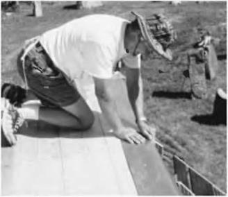
1. Begin with a drip edge all around the building. You can buy ten-foot sections of galvanized metal drip edge for about $4 a section, but I prefer to make my own from seven-inch-wide aluminum flashing, so that I can place a full five inches onto the deck, which makes it easier to apply the membrane, and to keep it from the sun’s UV rays. Fig. 5.36.

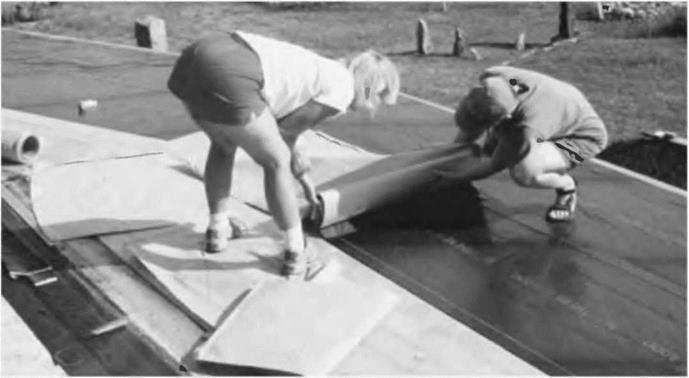
2. Install a good-quality waterproofing over the planking. I like the W. R. Grace Bituthene™ 4000 waterproofing membrane, because it is good quality, moderate in cost, and easy to install. Fig. 5.37.

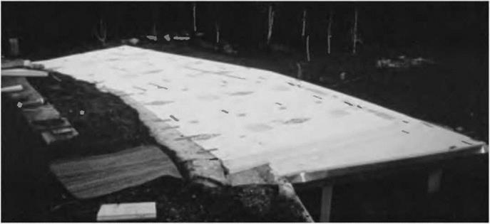
3. Over the membrane, install four to six inches (10.1 to 15.2 centimeters) of extruded polystyrene insulation, rated at about R5 per inch. Fig. 5.38.

4. Over the insulation, place a continuous layer of 6-mil black polyethylene. This cheap black plastic (you can do a 1,000 square-foot, or 93 square – meter, roof for $6o) is the base of the important drainage layer, which takes some burden off of the membrane. My earth-sheltered workshop

Fig. 5.37: Diane Lukaris and Jaki Roy roll out the Bituthene™ 4000 waterproofing membrane onto the wooden substrate, which has already been primed with a compatible acrylic primer provided with the product The backing paper is removed as the 36-inch – wide membrane is rolled out, exposing a very sticky bitumastic membrane that adheres extremely well to the primed wooden deck. The ladies are careful to maintain the required three-inch overlap between adjacent courses.

image144image145Fig. 5.38: We installed 4 inches of Dow Styrofoam™, an extruded polystyrene, over the membrane.

The Earth Roof

students know that my favorite mantra in this regard is: “Drainage is the better part of waterproofing. Give water an easier place to go than into your house.” Photos are unnecessary for the remainder of the earth roof commentary, but I will draw you a picture of the various roof layers for reference, which is Fig. 5.39. Please refer to the drawing as you follow the text.

5. Install the drainage layer, consisting of two inches (5.1 centimeters) of #2 crushed stone. This is stone about an inch (2.5 centimeters) in diameter.

6. Over the crushed stone, install two to three inches (5.1 to 7.6 centimeters) of loose hay or straw, which will eventually compress and decompose down into a natural filtration mat. It keeps the crushed stone drainage layer free of soil.

Fig. 5.39: Roofing detail for a free­standing earth roof using moss sods to retain the earth.

Key:

1. Above-grade wall.

2. Heavy wooden rafter.

3. 2" x 6” T&C planking.

4. Aluminum flashing as drip edge.

5. W. R. Grace Bituthene™ 4000 or equal membrane.

6. 4" to 5" rigid-foam insulation

7. 1" rigid foam or half-inch fibreboard to protect membrane.

8. 6-mil black polyethylene.

9. 2" of #2 crushed stone drainage layer.

10. Hay or straw filtration mat.

11. Moss or grass sods cut from sandy soil, retain the earth at the edges.

12. Подпись: 4image146Подпись: 1image1477" to 8" topsoil, planted.

7. Over the hay or straw filtration mat, install enough earth to maintain a living roof. In temperate climates with moderate rainfall, eight inches (20.3 centimeters) is enough. Saturated earth weighs 120 pounds per cubic foot (1,922 kilos per cubic meter), so, to keep timber sizes down to something reasonable, we don’t want to put any more earth up there than necessary.

8. Seed with whatever you like — grass, vetch, wildflowers. Mulch and water as necessary until the green cover is well established.