Value Engineering Change Proposals

As described by AASHTO, VECP programs differ from other VE programs in that the construction contractors develop the recommendations. The contractors choose whether or not to participate, with the incentive for sharing in any cost savings realized. Thus, the states must create and manage a program that will be attractive to the contractors. This program is called by different names in various states, for example, Value Engineering Incentive Provision (VEIP), Value Engineering Incentive Clause (VEIC), and Cost – Reduction Incentive Proposal (CRIP).

A contractor’s participation in a VECP program involves a certain amount of risk. It costs money to search for realistic savings that will be shared by the state, and the contractor cannot expect all proposals to be accepted. However, the program offers an opportunity for contractors to demonstrate ingenuity, innovation, and construction excel­lence, and to receive financial benefit.

Care should be taken to ensure that a VECP does not compromise any essential design criteria or any preliminary engineering commitments such as environmental mitigation measures. Specific construction elements, such as bridge-span lengths or type of noise barriers, may be excluded from consideration for a VECP, but such exclusions will limit potential savings opportunities. Any exclusions should be delineated in the specifications or other contract documentation.

Benefits. The VECP must not result in impairment of essential functions and character­istics of any part of the project including, but not limited to, service life, reliability, econ­omy of operation, ease of maintenance, desired aesthetics, and safety. The VECP program offers benefits to the state when it (1) enhances the design at reduced cost to the state, (2) results in a net savings over the contract cost, or (3) advances the project completion date. The program offers a low-cost opportunity to use the experience and creative talents of the contractor. Contractors participating in the VECP program take pride in contributing actively to the final development and construction of the project.

Contract Documents. To invite proposals from the contractors, the state should include in the contract document a VECP section, specifically defining basic requirements and evalua­tion criteria. Before initiating a VECP program, a state may want to secure an interpretation from the attorney general or other appropriate source as to the legality of their VECP provi­sions. VECP specifications and requirements are described in Section 104.07 of the latest version of AASHTO’s Guide Specifications for Highway Construction (visit the website www. aashto. org for information on how to obtain a copy). In an effort to promote a higher VECP participation, some states are studying the application of the VE job plan (see Arts. 10.3 and 10.4) in facilitated sessions with contractors that can include state employees.

Review Process. The review process for a VECP should include the development of a review schedule to ensure the reviewing agency can meet the contractor’s time frame. VECPs occur during the construction phase of a project and time is usually short. A schedule must be developed for those offices and/or persons who must review and com­ment on the VECP before final disposition. There should be a single point of contact for each state, to ensure no required office or person is omitted from the review process. The single point of contact also can act to enforce the review schedule. All comments resulting from the review should be compiled and resolved, with a final accept/reject recommendation to management. Proper documentation is essential. Complete and accu­rate estimates are required for correct savings calculations. The final step in the review process is justification. This is not a trivial step. Timely, accurate notification of all parties involved may reduce confusion and litigation, which also can be avoided by adding language to the state’s VECP provision.

Securing Adequate Contractor Participation. The first step in securing adequate contractor participation is to be certain the VECP program encourages, rather than dis­courages, such participation. For instance, the sharing percentage must be equitable. The VECP requirements, policies, and procedures should not be so legalistic, stringent, or cumbersome as to discourage contractors from participating, and there should be flexibility to meet changing conditions. Past experience indicates contractors need to be oriented to the VECP program and educated about VE methodology and procedures. A state initi­ating a VECP program should do what is necessary to ensure an effective contractor orien­tation and education program is developed and conducted. Otherwise, many contractors probably will be reluctant to participate. AASHTO suggests the following approaches to contractor orientation and education:

• The state should work closely with contractor organizations during the whole of the VECP program planning process. It is important to allow contractors the opportunity to review all elements of the program and provide input. The payoffs from this kind of a joint effort, in contractor support and participation, can be considerable.

• The state should encourage contractors to develop and conduct VE training courses. Where the state is conducting VE training for its own staff, contractor staff also could attend such programs.

• The contractor orientation, education, and promotion program should be a continuing one. Continuing efforts could include regular and periodic distribution of VE infor­mation and discussion of VE during preconstruction conferences.

Most of these approaches are obvious, and certainly many others could be developed to fit particular conditions. It is important to provide a well-planned, aggressive, and imaginative contractor VE program to enhance the probability of the success of the VECP effort.

Even though initial contractor participation is secured through this type of promo­tion, the VECP program will not be successful unless a high level of participation is maintained. AASHTO offers the following considerations for maintaining contractor participation:

• The state must ensure adequate opportunities for participation by providing a broad incentive clause in contractors’ standard specifications.

• Contractors must be assured of a fair and objective evaluation of their proposals. The state should take all reasonable measures to create positive attitudes toward contractor change proposals. It may be beneficial to involve the VE administrator in the day-to­day VECP.

• Contractors must be assured of timely processing of change proposals. To satisfy this requirement, the state must allocate adequate resources to the program. Additionally, to reduce the time and effort required by a contractor to submit a proposal, the proposal may be submitted first for evaluation. This initial proposal would outline the general technical concepts and the estimated savings.

The “belle epoque” of the Middle Ages, from the dawn of the 12th century to the Hundred Years’ War

The hydraulican-monks: Benedictines and Cistercians

We have seen that the earliest Benedictine monasteries at the end of the 8th century already were employing a range of hydraulic techniques to support their activity. Much later, in the 12th century, Saint Bernard founds the abbey of Citeaux in Bourgogne, and with it the order of the Cistercians. Throughout Europe (France, Germany, Holland, Portugal) the Cistercian abbeys are established near watercourses. But after several years of growth, these abbeys typically found it necessary to augment their water sup­plies through capturing other rivers or torrents.

The Obazine (Aubazine) abbey was founded in Limousin in 1130 by the hermit Eti­enne. This abbey quickly entered the fold of the Cistercian order. Here one can identi­fy the trace of the “canal of the monks” dating from around 1150. It is 1.6 km long aque­duct built in truly acrobatic fashion, sometimes laid along a cliff on cantilevered arches, sometimes crossing rocky outcrops. This little canal is only 1.2 m deep and 0.6 m wide; its slope is relatively flat along most of its length (5 m/km), but it ends in a virtual water­fall, descending some 60 m in its last stretch of 230 m. Several centuries later, the inge­nuity reflected in this canal is attributed to miracles performed by its founder:

“It should be further noted that the great Saint Etienne had an aqueduct built to bring water into the abbey, so that all normal needs of hygiene and cleanliness could be satis­fied. There has never been seen in France a better built or more expensive canal. It passes through inaccessible places where the Saint broke through the rocks, to the admiration of all those who see it, and, according to legend, we learn that one of these rocks, not having yield­ed after long and expensive efforts, finally crumbled of its own accord after prayers and the worthiness of the Saint to receive this flow of water.’,z, u

Citeaux is the initial site of the Cistercians, and at the end of the 12th century it was a very rich abbey. But the Vouge River on which it was situated did not have a suffi­ciently ample and regular flow to support the growing population of monks. The abbots covet the water of a gushing torrent called Cent-Fonts, some ten kilometers to the north of the abbey, which powers numerous mills belonging to several local lords. The abbots begin by obtaining a piece of land from one of these lords to build their own mill, between 1175 and 1180. Little by little, in exchange for salvation of the lords’ souls, they obtain significant land holdings for their scheme as well as shares in the mills that use the water of this torrent. Adding to their holdings through outright purchases, the abbots eventually own all of the mills. From the Duke of Bourgogne and the Bishop of Langres, the most important personages of the region, they obtain all the authorizations necessary for their project of capturing the Cent-Fonts, in return for which they agree to build and maintain bridges across the canal for the use of the peasants of Noiron, a vil­lage on the projected course of the canal (Figure 9.10).

The “belle epoque” of the Middle Ages, from the dawn of the 12th century to the Hundred Years’ War

Figure 9.10 Water and land development at the Cistercian abbey of Citeaux in Bourgogne: derivation canal, mills, pond drainage, between 1175 and 1227 (Berthier, 1996; Sonnet, 1998).

The canal itself is finally built around 1212. Some ten kilometers long and 2 m wide, it crosses the Varaude River, a tributary of the Cent-Fonts, on a 12-meter long canal-bridge (Figure 9.11). Its slope varies from 1.9 to 5.9 m/km, and it probably cap­tures all of the water of the Cent-Fonts (around 320 l/s). Indeed, the mills located between the canal intake and the confluence of the Varaude are left without any water and thus are abandoned. The monks develop the land that they have acquired, draining the fields crossed by the canal by digging ditches and creating ponds.[479]

The “belle epoque” of the Middle Ages, from the dawn of the 12th century to the Hundred Years’ War

Figure 9.11 The bridge of Arvaux, carryng the Cent-Fonts canal to the north of Noiron (reconstructed to the original in 1747) (photo by the author).

What did the monasteries do with all this water? In general terms the water was des­tined for two uses: pure water for human consumption, and abundant and fast-flowing water for hygiene and useful work. Captured source water is decanted in reservoirs, sometimes filtered, and then delivered to kitchens, bathrooms, laundries, and to the apartments of the abbot and his guests. In the monasteries of the order of Chartreux, whose rules require total isolation, each cell has its own supply of water and means of wastewater disposal. The supply pipes are made of clay or lead and even sometimes of wood. Water from a river powers the mills of the abbey, including at least one wheat mill and one fuller’s mill, and often several other multiple-purpose mills. Water circu­lates through the drains and keeps them clean, passes through latrines (the latrine of Royaumont being the most remarkable), and supplies the fish pond. Fish raising is very important, for the monks are forbidden to eat meat by the rules of Saint Benoit. This importance is emphasized by the large size of the fish pond of Obazine, which is 33 m long, 14.5 m wide, and 3 m deep.

The “belle epoque” of the Middle Ages, from the dawn of the 12th century to the Hundred Years’ War

Figure 9.12 The Cent-Fonts canal, on the Arvaux bridge (left), and where it arrives at the mill of the Cteaux abbey (right) (photos by the author).

Structure

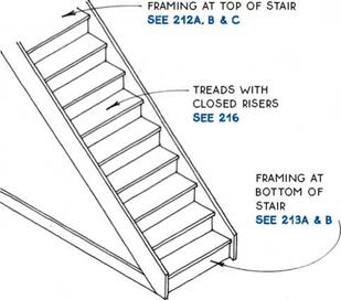
Stairs may be classified into two basic structural types: continuously supported and freespanning.

Continuously supported stairs—Continuously supported stairs are commonly used as interior stairs. Both sides of the stairway are supported by wall framing, so calculations of spanning capacities are not necessary. These stairs are site-built in some regions, but are predominantly prefabricated in others.

Structure

Continuously Supported Stair (Shown with Closed Risers)

Freespanning stairs—Freespanning stairs have the structural capacity to span from the bottom stair to the top stair without intermediate support. The freespan­ning stair is commonly used as an exterior stair between floors or landing levels or in conjunction with porches and decks. It is often also seen as an access stair to basements and attics. The strength of a freespanning stair is usually in the carriages (stringers) that support the treads, although the handrail may also contribute to the strength of the stair. Freespanning stairs, like continuously supported stairs, may be site-built or pre­fabricated. Some freespanning stairs have only a single central support.

Prefabricated Custom Stair (May be Freespanning or Continuously Supported)

Road Drainage and Treatments Systems

In recent years, it has been demonstrated that diffuse or irregular sources of pollu­tion, like runoff, constitute significant contamination points in the natural drainage system. In most cases one has to take appropriate measures to control this pollution. In general, the environmental aspect of a road project nowadays constitutes an in­tegral and fundamental part of the project, so that there is a strong interdependency between the various aspects considered in design and in the interventions that have

to be planned. In particular, it will probably be necessary to perform an integrated assessment of the road project itself, the drainage, the water resources, the quality of the water, the geology and the geotechnical aspects, with special focus on hydrol­ogy and landscape studies. Only in this way can one balance need for the road and the impact it will cause and allow the design, dimensioning and implementation of optimal and adequate systems for the conveyance and treatment of water flowing from the road platform.

The choice of treatment system to adopt has to address diverse conditions:

• the type of pollutants to treat (in particular heavy metals);

• the regional climate;

• compatibility with the roads’ drainage project;

• the impacts on the landscape; and, also

• the creation of a passive system, without the need of energy which, thereby, has great reliability and low maintenance needs.

Therefore, once the discharge points have been associated with particular, sensibly- sized, areas of the pavement platform, one can compute the discharge and proceed to study which treatment system should be adopted and its interaction with the drainage system.

The implementation of a project of this kind doesn’t overcome the need for an effective control of the treatment efficiency and this may be achieved through the application of an adequate monitoring system for the site. This should commence operation immediately after the start of the road use. Data can be obtained by sam­pling the pollutant charge in the runoff on first use. It will form a baseline against which to check any eventual flaws in functioning of the recovery and treatment system. Monitoring will allow the operator to detect, and thus rectify, any defects in a timely manner. The successful implementation of a sampling program of this nature will be very useful not only for the scheme in view, but especially for new situations, helping to find better project options which can be implemented in sub­sequent projects.

In parallel one should promote periodic maintenance and conservation action in the drainage network and in the treatment areas. In fact, without adequate mainte­nance the investment made will be likely to prove fruitless.

Team Structure

AASHTO gives the following guidance on structuring the VE team. A team of five to seven persons with diverse areas of expertise usually produces the best results. A team of fewer than five tends to limit the amount and variety of creative input, and a team of more than seven can be unwieldy. Teams should be structured so there is appropriate expertise to evaluate the major problem areas anticipated within the project, e. g., traffic, right-of-way, structures, soils, paving, etc. Including general expertise from the areas of design, construction, right-of-way, maintenance, or traffic operations makes for a good team balance.

Team Leader. One individual should be appointed as team leader to guide the team in its efforts and be responsible for its actions during the study. The team leader should be an individual who is very knowledgeable of, and proficient in, the VE process and able to direct the team’s activities toward its goal. Additional training in motivation and lead­ership techniques may be warranted for team leaders. A VE consultant serving as team leader should be a certified value specialist with highway experience.

Team Members. Representatives from disciplines other than engineering can provide greater objectivity to a team effort. Expertise from outside the state organization (e. g., local agency, citizen groups, United States Forestry Service (USFS), FHWA, consultants, etc.) may be appropriate on certain projects. Federal law prohibits individ­uals directly involved in the design of a project from being on the VE team analyzing the project; however, the original designer is an excellent resource individual for the team to consult. Specific training in the concepts, application, and techniques of VE is highly desirable for those working as VE team members. Occasionally, a team may include one or two members who are untrained in VE, but highly skilled in disciplines that are vital to the study.

ATTACHING A COUNTERTOP TO A. BASE CABINET

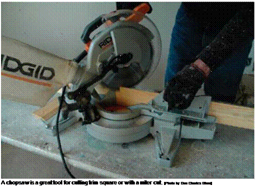
ATTACHING A COUNTERTOP TO A. BASE CABINETПодпись:Подпись: Take the saw to the work. If you have a chopsaw that's compact and light enough to carry, move it into the room where you're installing trim. This can save you time and energy when making the many required cuts.

An electronic stud finder will locate studs quickly and accurately. But if you don’t have one, there are other methods you can use. Look on the floor for keel marks that were used to locate the studs before drywall installation. Electrical-outlet boxes are nailed into studs. Tap gently on the wall and listen for a duller sound when you tap over a stud. Or drive nails behind the cabinet to locate a stud. When one stud is found, other studs should be 16 in. or 24 in. from it. Once the studs are found, mark their locations inside the cabinets on the mounting rail. Predrill screw holes in the cabi­net mounting rail, set the cabinet in place, and drive a screw into each stud. If the screw misses the stud, check again for its location until you get it right. And feel free to use a few extra screws in wall cabinets. Just make sure they go into studs.

Many types of countertops are available these days, but the most common type of afford­able countertop is plastic laminate applied over particleboard or MDF. Laminate countertops come in many colors and styles. Remember if you choose this type of countertop that scratches show up more on dark surfaces than on lighter ones. Also, be aware that very hot pans can leave burn marks on laminate countertops. Sometimes, a countertop is also needed in a bathroom, but often the bath vanity comes with a countertop and a sink already attached.

A countertop ends where it meets a wall or stove and extends 1 in. or so beyond the end of the last cabinet. When I’m ready to install a countertop, I go to a supplier, pick a color, and give the clerk the exact measurements of the base cabinets. I prefer the style of laminate countertop that comes with a backsplash. If you provide the size and location of the sink, the supplier can cut the hole for it, often at no additional cost (see the top photo on p. 257). Otherwise, a hole can be cut on the job site with a jigsaw or a reciprocating saw (sabersaw) equipped with a fine-tooth blade. Just follow the directions that come with the sink. Put some duct tape on the base of the saw to keep it from scratching the laminate surface.

In many Habitat houses, the kitchen layout provides for straight countertop surfaces rather than L-shaped countertops, which are more difficult to install. If you need an L-shaped countertop, the supplier will make the neces­sary miter cuts and provide special hardware for joining countertop sections from underneath. Before joining mitered sections, put waterproof silicone caulk on the two mating edges.

Test-fit each countertop section, placing it on top of the base cabinets and seeing whether the unit fits properly. If the backsplash doesn’t fit tightly against the wall, fill small gaps with silicone caulk after attaching the countertop. If necessary, especially on a crooked or wavy wall,

scribe a line on the backsplash and then use a belt sander to remove material from the back – splash to make it fit against the wall.

ATTACH THE COUNTERTOP WITH SCREWS. Usually, base cabinets are built so the top can be screwed directly to them. For some cabinet and countertop combinations, though, a supplier may advise you to put strips of 1 x material on top of the base cabinets so the countertop nosing won’t prevent cabinet doors and drawers from opening.

Prefinished countertops must be attached with screws from below. Attach the countertop by driving Р/4-in.-long screws up through the 1x mounting blocks installed by the cabinet manufacturer (see the illustration on the fac­ing page). Predrill a screw hole through the mounting blocks, but be very careful not to drill or drive the screws so deeply that you break through the finish surface. It’s easy to strip a screw driven into a countertop’s particleboard or MDF substrate, so don’t try to drive installation screws extra tight. Complete the job by running a neat bead of silicone caulk between the back – splash and the wall.

STEP 6 INSTALL THE BASEBOARD AND CHAIR RAIL

The old house I grew up in had full 1×12 base­boards. In our part of the country, they were called mopboards. In those days, people used big mops to clean their floors with soap and water. The baseboard not only covered the joint between the plaster and the floor but also pro­tected the walls from being banged by the mop.

Today, baseboard trim is made from real or manufactured wood, and there are many styles available. In the last Habitat house we built here on the coast, we used 1×4 baseboards made of preprimed MDF. Once it was installed and painted, it looked great, but it was so solid that you could hardly drive a nail through it by hand.

Подпись:ATTACHING A COUNTERTOP TO A. BASE CABINETIn other houses, we have used 3-in.-wide trim that’s about 3/8 in. thick at the bottom and slopes up to a slender top edge. The thin edge

Подпись:Подпись: Short trim splits easily. Short pieces of trim must be predrilled so nails won't split them. If a short piece of trim fits snugly in place, you can simply glue it without using nails. Подпись: Inside baseboard corners are coped. The coped cut fits the profile of the trim piece that runs into the corner. [Photo © The Taunton Press, Inc.]

makes it harder for dust to collect on the top. Baseboards still cover the joint between the drywall and the floor and keep the wall from getting banged by a vacuum cleaner. Order long stock from the supplier so you can eliminate joints on most walls.

Install the baseboard trim

Before installing baseboards, use a putty knife first to clean any excess joint compound from the corners. Then clearly mark (or re-mark) the location of the studs on the floor. If the gap between the bottom edge of the drywall and the floor is greater than 1 in., take the time to fill it with strips of ‘/i-in.-thick OSB or plywood. Otherwise, the bottom part of the trim can easily be canted inward during installation. If you’ll be nailing the baseboard by hand, protect your knees with a pair of kneepads.

Paint-grade MDF is a material commonly used in baseboard and door trim. It is not advis­able to use this material in bathrooms, kitchens, or laundry rooms. MDF absorbs water easily, caus­ing it to expand. It will then have to be replaced.

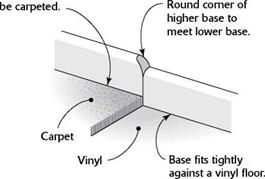
Right-handed people generally prefer to install baseboard counterclockwise (right to left), starting at a door. This makes it easier for righties to cut a coped joint. Lefties tend to install baseboard clockwise for the same reason. Set baseboard right on vinyl or wood flooring, but hold it up about Vi in. if you plan to install carpeting later so that you can slip the carpet under it. When working in rooms that will later be carpeted, use small blocks of OSB as tem­porary supports under baseboards as you nail them to the wall.

To get my trim skills up to speed, I like to start running baseboard in a closet. Try mak­ing a rough plan of each room on scrap paper and record the measured length of each wall. Drywall is often left a bit rough near the floor line, so it’s hard to measure accurately at that point. Hold the tape off the floor a couple of inches to get a more accurate measurement.

This will save you time walking back and forth to the chopsaw with a new measurement each time you want to make a cut.

The first piece right inside the door is mea­sured to length from the door casing to the wall and cut square on each end. Often, that piece is quite short (2 in. or so). If it fits snugly in place, you may not need to nail it. Instead, spread some glue on the back and just press it into posi­tion. The next piece of trim will hold the short

ATTACHING A COUNTERTOP TO A. BASE CABINET

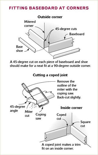
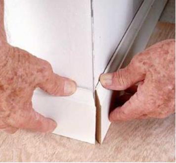
Outside corners are mitered. Two pieces of base­board cut at 45-degree angles should meet to form a neat, tight 90-degree corner.


MARK THE BASEBOARD AT OUTSIDE CORNERS AND ON LONG WALLS.

I prefer marking trim for outside corners in place rather than determining the length with a measuring tape. Position a piece of trim along the wall. Make a mark where the top of the trim meets the corner. The cut will be the short point of the 45-degree miter. The two mitered pieces of baseboard meet at a corner and make a 90-degree angle (see the photo at left).

If an outside corner is not square, adjust the cut to make the miters fit (see the sidebar on p. 262). A bit of glue on the corner will help hold the joint secure. Drive a 4d nail through the face of one baseboard and into the end of


Pneumatic gun nails are la­beled in inches rather than by “d”. So rather than looking for an 8d nail, you need to look for a 2-in. gun nail. These nails are thin with a square point, which allows them to be driven into wood without split­ting it.


INSTALLING BASEBOARD ON THE WALLS
ABOVE CARPETED AND VINYL FLOORS


one until the glue sets. Use 6d finishing nails for ‘/^-in.-thick trim and 8d nails for 3/4-in.-thick trim. Space the nails about 16 in. apart, and drive them into either the bottom plate or the studs. Driving each nail should pull the trim tightly against the wall.

The second piece of baseboard is coped to fit against the first piece and cut square to butt against the next wall. On the end that will mate with the short piece of baseboard, cut a 45-degree miter that is long on the back (so you can see the cut surface). Now use a coping saw to cut the outline of the profile left in the exposed end grain (see the sidebar on p. 259). The cope-cut end will fit snugly against the first piece of base­board (see the bottom photo on the facing page). Trim for inside corners that will be painted can be fitted together with a miter cut rather than a coped joint. If the fit isn’t perfect, you can fill it with a bit of painter’s putty.

As an alternative to making coped cuts for inside corners, some builders install manufac­tured corner blocks, which are available in sever­al styles. Each block is simply glued to an inside corner; baseboard trim can then be cut square to butt against an edge of the corner block. A similar type of block is available to fit on outside corners that are covered with a rounded drywall bead rather than with a square one.


Hold base up 1/2 in. from floor that will

ATTACHING A COUNTERTOP TO A. BASE CABINET


Baseboard


On a vinyl floor, a base shoe can be nailed at the bottom of the baseboard.


Base

shoe


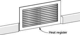
Where baseboard runs into a heat register, cut the baseboard back 15 degrees on both sides to soften the ends.


ATTACHING A COUNTERTOP TO A. BASE CABINETATTACHING A COUNTERTOP TO A. BASE CABINET

Study Selection and Scheduling

As previously indicated, states must perform a VE analysis on all federal-aid-funded projects on the National Highway System having an estimated total cost (design, construction, right-of-way, and utilities) of $25 million or more. However, additional projects should be selected for study, based on providing the maximal opportunity to improve the public investment by quality enhancement or life cycle cost savings. AASHTO has identified the following typical characteristics of potential VE projects:

• Projects substantially exceeding initial cost estimates

• Complex or multipart projects or processes providing unique, but costly functions

• Items using critical or high-cost materials

• Items requiring difficult construction or fabrication procedures

• Items performing a questionable function

• Items appearing too costly to build, operate, or maintain

• Projects that have grown complex, possibly by development over a long period of time

• Major structures

• Projects with complicated or costly traffic control or detours

For optimal results, VE should be applied as early as possible after basic design elements and preliminary cost information have been developed. This way, design rec­ommendations can be more readily incorporated; the earlier VE is applied, the greater the potential for savings. With proper timing and planning, the VE administrator can ensure that specific VE studies are accomplished without conflicting with the project schedule.

Chair rail adds character

Chair rail is another type of traditional trim that is installed horizontally and often used in kitchens, dining rooms, and sometimes hall­ways. In days past, chair rail protected the wall

from being marred by the backs of chairs. Today, it is mainly used to add character to a room. Chair rail is cut and installed just like baseboard (see the photo below). Join two pieces with a coped joint at inside corners and a mitered joint at outside corners. Nail the chair rail directly to the wall studs, with the top of the rail 36 in. from the floor.

STEP 7 Trim Out the Closets

Most closets in affordable houses get nothing more than a shelf and a pole. It’s my opinion that we can do much better without a lot of effort or expense. Very little extra material is needed to add shelves for socks and under­wear, to make a place to hang belts and ties, and to make cubbyholes for shoes. Experience tells me that people like and use such storage. Even if you don’t want to build special storage bins, you can buy them. Many people now use the wire shelving available at home centers.

Install shelves and poles

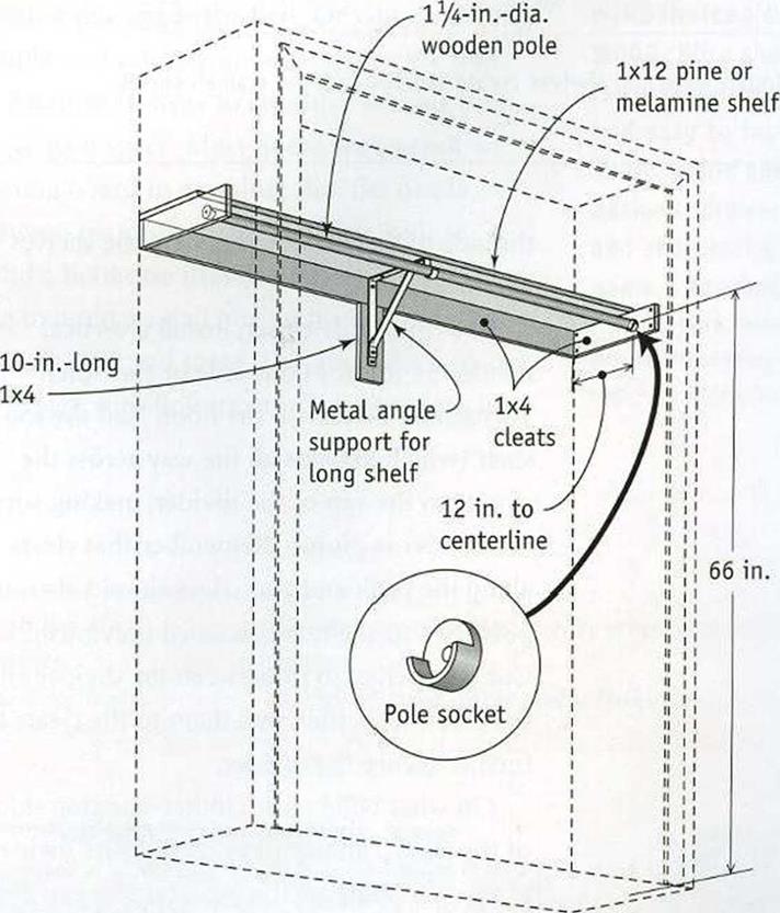
To install a basic shelf and a pole in a closet, measure 66 in. from the floor and mark the back and sides of the closet (see the illustra­tion on the facing page). Then cut cleats (also called rails or ledgers) from 1×4 stock, and nail each cleat so its top edge is on a line. Drive two 8d finish nails through the lx rails and into each stud.

Cut the shelves from 1×12 pine or mela­mine (particleboard covered with white plastic laminate). A standard closet shelf extends from wall to wall. I like to secure the shelf with a couple of nails driven into the cleat. It’s a good idea to predrill the nail holes.

In a small closet, where the shelf and pole are just 3 ft. long or so, no mid-span support for the shelf or pole is necessary. Each end of the pole rests in a socket that is screwed to a side cleat.

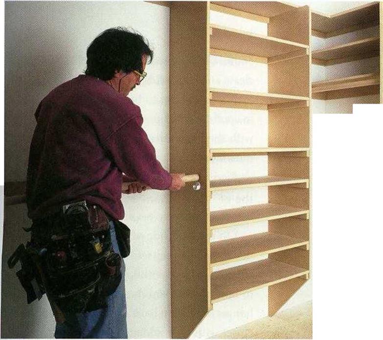
Подпись: ■ У-Шг'-Подпись: <хлПодпись: '.-У-ЛПодпись: ■ш ■ЙМ Подпись: ■ ■>.Подпись: ■•■Л-'ЖПодпись: ...Chair rail adds characterSHELVES CUSTOMIZE A CLOSET. Attaching shelves to a closet wall creates more storage space whi*le giving you more flexibility in locat­ing the closet pole.

[Photo by Roe A. Osborn, cour­tesy Fine Homebuilding maga­zine, © The Taunton Press, Inc.]

In a larger closet, both the shelf and the pole need additional support from metal brackets. Place a bracket against a side cleat to determine the location of the pole sockets.

This ensures that the sockets and brackets will support the pole at the same level. Attach the top part of the bracket to the 1×4 horizontal cleat on the back wall, then nail a 10-in.-long piece of 1×4 perpendicular to the cleat and over a stud to support the bottom of the bracket (see the illustration at right).

Add smaller shelves to a closet

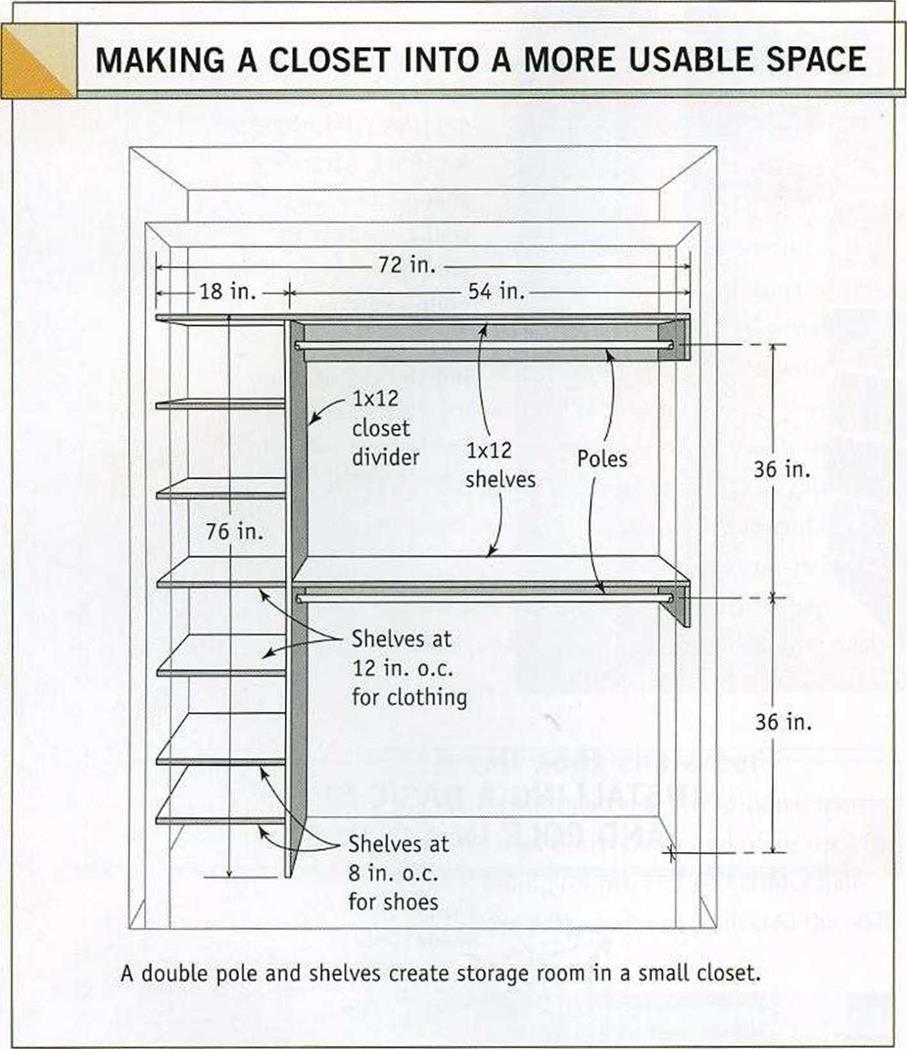
Rather than always running a shelf pole all the way across a closet, you can shorten the pole and add a column of shelves at one end, as I shown in the illustration on p. 266. With this design, you can make a typical 6-ft. closet much more useful for storing all kinds of clothes, including shoes. Cut the 1×12 divider 76 in. long, lay out the shelf locations, then attach 1×2 shelf-support cleats to the divider.

Подпись: INSTALLING A BASIC SHELF AND POLE IN A CLOSET Chair rail adds characterI usually place the two lowest shelves 8 in. and 16 in. off the floor for shoes. For socks and underclothes, I place a shelf every 12 in. above the first two. Fasten corresponding cleats to
Chair rail adds character

the side of the closet wall where the shelves will be installed.

In a 6-ft.-wide closet, install a vertical divider 54 in. from one side or the other. Toenail the divider to the floor. Nail the top shelf (which extends all the way across the closet) to the top of the divider, making sure the divider is plumb. Remember that cleats along the back and end edges should also sup­port the top shelf, as discussed previously.

Cut the shelves to fit between the divider and the closet wall, then nail them to the cleats to further secure the divider.

On what will be the clothes-hanging side of the closet, attach a 1×4 cleat to the divider at 66 in. to support the pole. Or you can install two poles, one at 72 in. and one at
36 in. The pole sockets are attached to the cleats and the divider.

If you’d prefer to buy shelving rather than make it, you can find plastic-coated 1x12s with shelving holes already drilled in them at most home centers. The shelves sit on small shelf pins that fit into the holes drilled into the divider. This allows you to adjust the height of shelves, just as in a kitchen cabinet.

On the pole side of the divider, put a few hooks to hang belts. On the cleat holding the shelf on the other end, install a hook or two to hold clothes you don’t want to put on a hanger. Now you have a much more usable closet with little added expense or labor.

Trim out a closet with coated-wire shelving

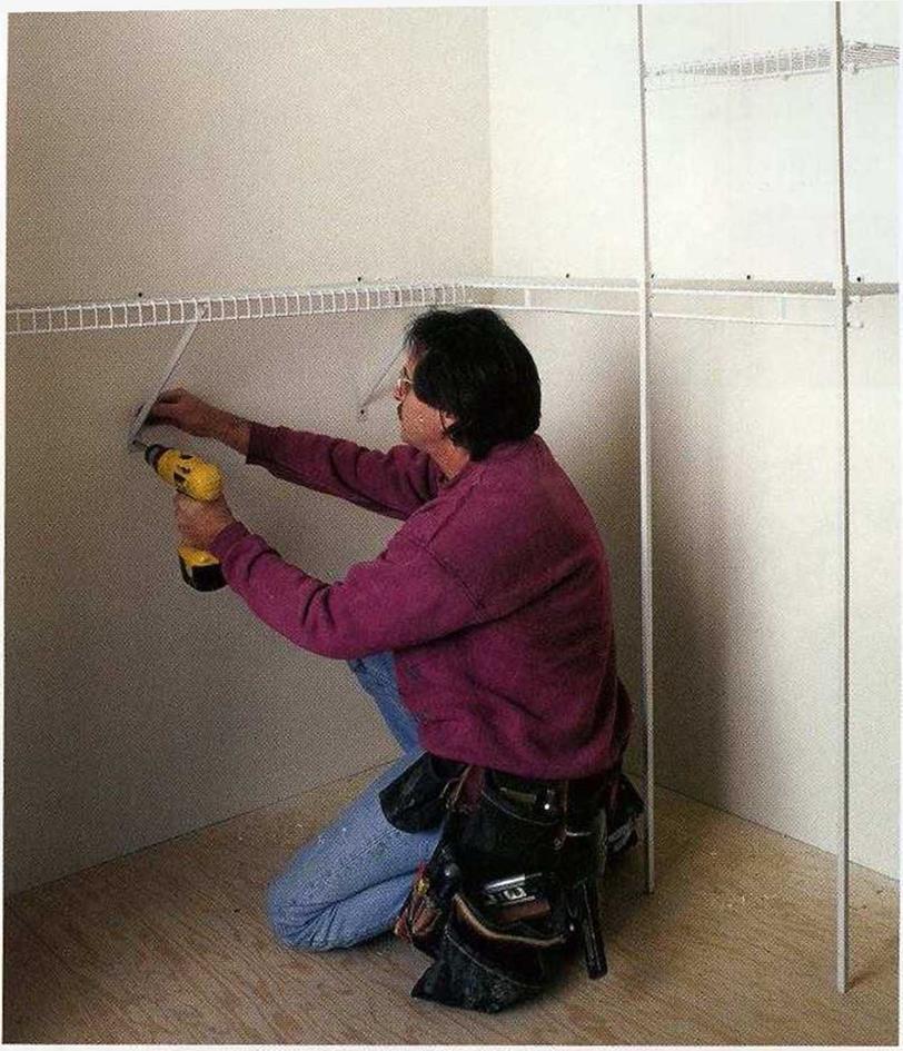
The rubberized wire shelving found at home centers offers many accessories to help orga­nize a clothes closet. The wire frames are strong and open, and you don’t have to paint them (see the photo on the facing page). Besides the traditional shelf-and-pole setup, you can install baskets, drawers, and tie, belt, and shoe racks. The possibilities for arranging your closets with these components are really endless. The only drawback is that they’re more expensive than building simple storage spaces with wood.

1 haven’t installed a lot of this type of shelving, but it isn’t difficult. The instructions that come with the components are easy to follow. Just be sure to make accurate measure­ments so the shelving is installed straight and level. Some people put backing in the wall frame before drywall is installed so the hooks that hold the wire units can be screwed into solid wood. Otherwise, you can screw the hooks into studs and then use the drywall anchors that come with the shelving units in places where you need support but don’t have a stud.

Chair rail adds characterInstall shelves in linen closets and the laundry room

A complaint I hear from many homeowners is that they just don’t have enough places to store their belongings. Certainly, most of us could stand to reduce the clutter in our lives, but adequate storage space is in short supply in small, affordable houses. For that reason, it makes sense to get the most out of whatever storage space you do have.

Just as in a clothes closet, you can do a lot with a linen closet by building shelving like that shown in the illustration on the facing page. I like to install the first shelf at 18 in. to 20 in. off the floor, then place shelves every 12 in. to 16 in. up from there. Use 1×2 cleats on each side of the closet, and attach the shelving to the cleats.

Take advantage of all the space in a linen closet (usually around 24 in.) by using full – depth shelves. Melamine shelving is available in various standard widths up to 24 in., or you can buy 4-ft. by 8-А. sheets of the material and cut it to the desired width.

Laundry rooms are oAen just large enough to hold a washer and dryer. Few affordable houses have a large utility room with space for lots of shelves. In a small laundry room,

I install a couple of shelves over the washer and dryer for items such as soap and bleach.

I install the first shelf at 5 ft. off the floor and

Chair rail adds character

another one above the first. Or you can buy a simple wall cabinet and attach it to the wall.

Подпись: Bringing pipes and electrical wire through the back of a base cabinet calls for careful measurements . . . We tackle the baseboard trim after all the cabinets have been installed . . . Подпись: Cutting exact angles is easy when you have a chopsaw . . . A tight-fitting miter really looks nice.

Подпись:Chair rail adds character

Chair rail adds character

Another strategy to consider is using built – ins to gain space. Most home centers sell an ironing board in a cabinet that fits neatly between two wall studs. You may want to build a bookcase that fits into the wall. I often like to build a small box with a shelf to place in walls here and there. This provides a place for a vase with flowers or other knickknacks.

Windmills: medieval innovations?

The use of wind energy (over and above the powering of sailboats) had begun on the Persian-Afghan plateau in the 7th century. It then spread to China from the 12th centu­ry as we have seen in the preceding chapter. At the beginning of this century, windmills began to see rapid development in Europe as well. Did the idea come from the Crusades, or perhaps from Sicily or Spain? Or did it arise, as we have proposed for tidal mills, quite independently? After two centuries of Muslim occupation, Sicily became Normand from 1061. The geographer al-Idrissi, residing in the court of the Normand king Roger II, gives us a hint of the Sicilian use of the horizontal-wheel Persian mill: “One can find there (in the Sicilian village of Calatubo) a quarry where stones are cut for both water mills and mills called “Persian”.”[474]

Подпись: Figure 9.7 One type of post mill (Belidor, 1737 -ancient archives of ENPC).
Windmills: medieval innovations?

Therefore it seems possible that the idea of using wind instead of water came from the Orient. But the medieval European concept of a windmill, with blades in a vertical plane, is quite different from that of the Persian mill.

First of all, in Europe these were post mills. The mechanism of a post mill sits in a wooden enclosure. The mill’s four blades are constituted of cloth stretched on a light­weight wooden frame to which the sails are tied, apparently in nautical fashion. At night the cloth sails are removed and folded. The entire assembly, including both the sails and the machinery within the enclosure, can be rotated around a sturdy oak pivot solidly anchored or lashed to the ground, thus making it possible to orient the sail into the wind. A long beam protrudes from the rear of the enclosure, like a tail or lever, to facilitate rotation of the mill. It is said that in Lincolnshire, a horse harnessed to this beam got entangled in the straps and dragged the mill around two full turns before the frantic ani­mal could be calmed down.[475]

This concept had its roots either in the flatlands of Flanders or in England. The known points of reference in Flanders are from 1114 (the Hofland mill) and 1127 (North mill). Those in England are from 1137, when a text mentions the gift of a windmill to the abbey ofReading; then in 1155, Sussex. Four other references to mills between 1180

Windmills: medieval innovations?

Figure 9.8 An ancient post mill at the edge of the Loire valley, upstream of Saumur (photo by the author).

and 1190 are from Flanders, at the mouth of the Somme River, and here are some twen­ty other references from England. This type of mill then spreads rapidly to other regions, since evidence exists from Germany in 1222, from Denmark in 1259, and from Holland in 1274. Some 120 windmills are known to have existed in the Ypres region in the 13th century. Others are found in Russia and at Venice in the 14th century.[476]

A second type of mill with its blades in a vertical plane appears in the Mediterranean area in the 13th century. In this region it was probably very difficult to find the kind of

Windmills: medieval innovations?Figure 9.9 Remains of a tower mill on a hilltop in the northern extremity of Corsica. In this particular case, the unit cannot be turned into the wind (photo by the author).

Figure 9.9 bis Ancient windmills in Crete, on the Lassithi plateau (photo by the author).

massive wood necessary for fabrication of a pivot. Thus was born the tower mill, in which the mechanism and the millstones are inside a round masonry tower. Only the conical roof of the tower, through which the horizontal axle extends, rotates to orient the sail into the wind. The sail itself also evolves to become more rigid in this kind of mill. Before long, and especially in Mediterranean regions, the technique of a sail stretched over a wooden frame, as for the pivoting mill, begins to disappear. Now each sail is of triangular shape like the lateen sails of Mediterranean sailboats, and is rigged on one spoke of a wheel as it would be on the mast of a ship. The sail is shaped by being sheet­ed to the neighboring spoke. This new concept for a mill apparently first appears in France or in Portugal in the middle of the 13th century; it then spreads toward the east­ern Mediterranean basin during the 14th and 15th centuries.[477] A tower mill dating from 1220 can be seen in Normandy (the Moulin de Pierre of Hauville).[478]

Biensi

This tiny structure, and those fol­lowing it, are different than the ones on the preceeding pages. Inside you will find a single open room. Just add closet(s), a loft, utilities and furniture as needed. The pictures on the following pag­es show how my friend Greg man­aged to fit everything he needs to live full-time in his Biensi. Visit www. resourcesforlife and click on “mobile hermiage” for more about Greg and his house.

House width: 8’

House length: 15’

Road Height: 13’-5” Dry Weight: 4400 lbs

Porch: 3’x 7%’

Ceiling height: 6’-3” – sizes are approximate