PREPARING FOR SANDING

After testing floors to determine their finish, empty rooms of all movable items (don’t forget window blinds and shades). Then use 3-mil poly­ethylene sheeting to cover the cabinets, radiators, smoke detectors, doorways, and heating or air­conditioning openings, using painter’s tape to avoid pulling paint off the walls and trim. Dust migrates through the smallest openings, so use painter’s tape to seal the perimeters of closed doors and keyholes. Because baseboards will get bumped by edgers, remove them if possible— though often that’s not possible. Alternatively, you can use a metal shield to protect such trim, as shown in the top photo on p. 493.

Подпись:Vacuum the floor so you can survey it closely for nails sticking up, and floorboards that are split or uneven. Use a nail set to sink nails below the floor surface. If boards are uneven or cup­ping, you may be able to sand them down evenly if they are solid wood. If any boards are split or splintered, replace them now.

Productivity

Your objective is most likely to frame a quality building for the least possible cost. Wages represent the greatest percentage of the total cost, and since wages are paid for time spent working, it follows that if you lessen the time it takes to complete a building, you thereby reduce the wages paid and, thus, lower the total cost.

There are various tasks involved in framing. Some of the tasks can be done as fast, or nearly as fast, by the least experienced framer as by the most experienced framer—for example, carrying and spreading studs. Suppose that a $10/hour person can do the same job as a $20/hour person, only 20% slower. You save $8/hour by having the less expensive person do the job.

Be careful, however, because if an inexperienced framer takes on a job beyond his capabilities, the chances for mistakes are great. This could result in wages paid for work incorrectly done, and higher wages paid for an experienced framer to find and correct the mistake.

It is ideal for you to have a balanced crew of experienced and inexperienced framers. This allows you the flexibility to fit the framer to the task. It takes planning to coordinate framing tasks so that they are done as inexpensively as possible, but it is time well spent for the money you will save.

The following are job titles and responsibilities for a typical large framing crew, divided into four categories: overall organization, walls, floors, and roofs.

3) Wall nailer

□ Nail walls together.

4) Makeup framer

□ Nail together a quantity of stud-trimmers, corners, backers, headers, etc., before they are carried to the walls.

Floors

Joisting

1) Rim joister

□ Nail joists in position.

□ Header out joists.

2) Joist nailer

□ Nail joists in position.

□ Nail on joist hangers.

□ Nail blocking and drywall backing.

3) Joist spreader

□ Carry joists into place.

Sheathing

1) Sheathing setter

□ Place and set sheathing.

2) Sheathing nailer

□ Glue joists ahead of setter and nail sheathing behind setter.

3) Sheathing carrier

□ Carry sheathing to setter.

Roofs

1) Spreaders

□ Spread and install trusses and rafters.

□ Install fascia.

2) Blockers

□ Install blocking and drywall backing.

□ Set sheathing.

3) Sheathing packers

□ Carry sheathing to setters.

Typical large framing contractor crew (continued)

Benefits of a VE Program

The main benefit of a VE program is improvement of the benefit-to-cost ratio throughout state transportation programs. Other perceived benefits are as follows:

• Design, construction, and maintenance standards are constantly being reviewed through VE team activities.

• The structured, functional approach using a job plan (see Arts. 10.3 and 10.4) provides trained employees with a new method of approaching problems.

• VE team members develop an appreciation for the concerns and issues of other functional areas or disciplines, and communications are often improved.

• Team work skills and team dynamics are enhanced in the design process.

• Designers improve or develop their skills in preparing and delivering to management logical, organized presentations supporting their views.

• After gaining VE experience, many designers find it comparatively easy to apply the principles in the regular design process.

• Implementing a VECP program has a potential for improving state/contractor relations through more cooperative processing of change proposals.

• Proven VE designs or techniques and VECP-accepted changes often have applica­tions for numerous future projects or contracts, thereby providing continuing savings and other benefits.

10.2.2 Training

AASHTO recommends that orientation and training be provided at nearly every level within the organization, including team members, team leaders, and management. Executive management must understand and support the fundamentals and principles of VE for the program to be successful. VE administrators, team leaders, and team members need basic and subsequent training to ensure success of the VE process and the implemen­tation of recommendations. An overview of the procedures and the benefits of VE should be provided to staff not directly involved to encourage understanding and support.

Training in VE is available from various sources, including the National Highway Institute and consultants. A combination of VE theory and hands-on experience is desirable. SAVE International (formerly Society of American Value Engineers) offers several forms of VE certification. (See www. value-eng. com.) To become certified, one must meet all of the employment, VE performance standards, formal training, pro­fessional growth, and professional contribution requirements established by SAVE. The following certifications are available:

• A value methodology practitioner. Individuals who are familiar with VE but whose primary occupation is not VE.

• An associate value specialist. Individuals familiar with VE, but who have not acquired enough points to become a certified value specialist.

• A certified value specialist (CVS). Individuals whose principal occupation is VE.

To become a CVS, one must attend a 40-h SAVE-certified Mod I VE workshop and a 24-h SAVE-certified Mod II VE workshop, have 50 percent or more of the job description relate to VE, perform a number of VE studies as a team member and as a team leader, write a paper on VE, and take a test. Normal time to become certified is 4 to 5 years.

The Energy – Smart Kitchen

The Energy - Smart Kitchen
Подпись:

W

hen it comes to electricity consump­tion, the kitchen is the hungriest room in the house. Kitchen appliances— including refrigerators, freezers, ranges, and dishwashers—account for nearly 27% of household electricity use. Collectively, that’s more than 300 billion kilowatt hours (kwh) per year in the United States, or roughly the electricity output of 90 average-size coal – fired power plants.

Not all appliances are equally voracious, however. Refrigerators and freezers account

for nearly two-thirds of kitchen energy use, with ranges, ovens, and cooktops ac­counting for a little over one-quarter, and dishwashers the rest. Add in the heating, air-conditioning, hot water, and lighting used in a kitchen, and this room is clearly the energy hog of most houses. Putting your kitchen on an energy diet might be one of the best things you can do to save money and resources. Like most diets, it all comes down to making informed choices.

Подпись: Two Tools to Measure Energy EfficiencyПодпись:ENERGY STAR

The Energy - Smart Kitchen

Refrigerators Are the Top Energy Guzzlers

In a typical American home, the refrigerator accounts for about 15% of total electricity use. Assuming heat and hot water are not electric, that makes the refrigerator a home’s single largest electricity consumer. This is the case even though refrigerators have im­proved dramatically since the mid-1970s; today’s models use about a third as much power as those from 30 years ago.

Techniques FITTING BASEBOARD IN IMPERFECT CORNERS

Techniques FITTING BASEBOARD IN IMPERFECT CORNERSTHE JOINTS IN BASEBOARD SHOULD BE CLOSE TO PERFECT. Minor touchups with latex caulk can be done before painting. Unfortunately, it’s not so easy to make perfect joints at corners when the drywall is not straight or a corner is not square.

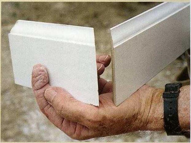
On inside corners, drywall can be tipped back, caus­ing a coped or mitered baseboard joint to open.

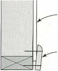
This can be remedied by putting a shim behind the tipped trim so that it sets straight up and down.

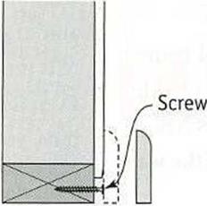
Instead of a shim, I sometimes drive a drywall screw into the bottom plate to hold the baseboard square (see the illustration below).

I use two short pieces of baseboard with mitered

Подпись: rywall, especially in the corners, an taper inward, causing the iseboard to pull away from іе wall at the top.Подпись: To prevent this, drive a drywall screw into the bottom plate behind the baseboard to hold the baseboard plumb.Techniques FITTING BASEBOARD IN IMPERFECT CORNERS

PREVENTING BASEBOARD FROM TOEING IN

Techniques FITTING BASEBOARD IN IMPERFECT CORNERS

Drywall

Baseboard

(45-degree) ends to check outside corners for square (see the photo above). If the mitered joints fit per­fectly, the corner is square. If not, note whether the joint is open at the heel (the back corner of the baseboard) or at the toe (the front edge). If it’s open at the heel, set the chopsaw at a 44-degree angle (or less, if necessary) before making the cut.

If it’s open at the toe, set the saw at a 46-degree angle (or more, if appropriate). Rather than waste long pieces of material, make practice cuts on scrap until you get the right fit.

FINISH UP. Pieces of baseboard will be at slightly different elevations where carpeting meets vinyl flooring. Join the two pieces of baseboard with a square cut, and use sand­paper to round the corner of the higher piece so that it meets the lower one (see the illustra­tion on the facing page).

Other situations require a bit of finesse.

For example, you can’t run baseboard in front of a heat register that goes all the way to the floor. In that situation, bevel each end cut 15 degrees instead of making a right-angled cut (see the illustration on the facing page).

Cabinet manufacturers sometimes supply a prefinished baseboard that matches their cabi­
nets. This base material is cut and nailed under the front of the cabinets in the toekick space. Once installed, it hides the joints between the cabinets.

If that cabinet trim is not available, you can cover the toekick area with a regular piece of baseboard trim. You may also want to install base shoe, or shoe trim, a small, quarter- round type of molding that is often used with baseboard trim (see the illustration on the fac­ing page). Shoe trim hides any space that may exist between the baseboard and hardwood or vinyl flooring. Because it’s so small, it’s quite flexible (much more so than baseboard), so it can be bent to fit the contour of a wavy wall

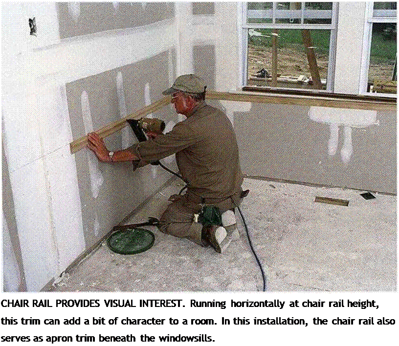
Подпись: I •— IПодпись: Helping HandПодпись: Offset closet doors make sense. Instead of framing a closet doorway in the center of the closet space, consider offsetting the doorway. This will make it easier to customize your closet space with cubbyholes, drawers, and poles.Подпись: CHAIR RAIL PROVIDES VISUAL INTEREST. Running horizontally at chair rail height, this trim can add a bit of character to a room. In this installation, the chair rail also serves as apron trim beneath the windowsills. or floor. It is not needed with carpeting because carpeting fills the space between the baseboard and the floor.

If you’ve hand-nailed all the interior trim, you now need to drive all the finish nails below the surface of the wood with a nail set. Once set, the holes can be filled with putty and sanded in preparation for painting. Caulk along the top edge of the baseboard trim and along the casings to fill any gap between the trim and the wall. Remember that caulk shrinks, so some gaps may need a second application. Take your time when caulking baseboard. Leave joints looking neat, not messy.

AASHTO ROLE IN VALUE ENGINEERING

To assist state DOTs in the application of VE, the AASHTO Task Force on Value Engineering, originally organized in 1985, has developed the publication, Guidelines for Value Engineering, already cited. Portions of the publication[22] are summarized in Arts. 10.2.1 through 10.2.6. The AASHTO value engineering technical committee maintains a useful website, www. wsdot. wa. gov/partners/AASHTOVE. Also, a VE engineering conference is sponsored every 2 years.

AASHTO has taken the position that every member state should establish an ongoing VE program to improve design excellence and achieve cost and quality control. VE is seen as a means for addressing the problem of rising costs and diminishing resources through applications in many areas such as project development, construction, traffic operations, and maintenance.

10.2.1 Elements of a Successful VE Program

AASHTO suggests the following as important elements of a successful VE program:

• A firm commitment of resources and support by executive management is the most important element for ensuring the success of a VE program.

• All levels of management must understand and support VE.

• A state VE program requires the development of a policy directive describing where, when, how, and to what specific areas of work the VE effort should be directed.

• It is essential to provide some degree of VE training and program familiarization at every level within the state organization.

• For optimal results in the project development phase, VE should be performed as follows:

Early in the planning-design process to maximize potential product improvement and cost savings.

On high-cost and/or complex projects.

By a multidisciplinary team of professionals trained in VE techniques.

• A value engineering change proposal program to encourage contractors to develop construction VE proposals allows the state to benefit from a contractor’s design and construction ingenuity, experience, and ability to work through or around bureaucrat­ic restrictions. Some important elements of a successful, ongoing VECP program are the following:

Processing of proposals must be kept simple and done quickly.

Cost savings are shared with the contractor.

Change proposals become the property of the state, and the concept may be used on future projects.

Change proposals should not compromise any essential design criteria or preliminary engineering commitments.

Change proposals cannot be the basis for a contract claim. The state agency has the option to reject, with good justification, contractors’ proposals.

• It is essential that all VE team recommendations and contractor proposals be fairly reviewed and expeditiously evaluated for implementation.

• VE techniques can also be used to improve productivity in other areas of a state’s transportation program, including traffic operations, maintenance processes, proce­dures and operations, standard plans and specifications, and design criteria and guidelines.

• VE programs within the state organization should be closely monitored, evaluated, and modified to ensure the program’s effectiveness.

It is also emphasized that understanding and support of VE by top management are the most important factors in a successful VE program. Such support is needed initially to ensure adequate funding for training of staff and establishment of the program. Once the VE program is established, the continuing active involvement of top management is needed to create and maintain positive attitudes.

FHWA VE Policy Guide

The FHWA has developed the following federal-aid policy guide that provides much useful information for the application of VE:

1. PURPOSE. To provide policy guidance on the application of value engineering in

the federal-aid highway program.

2. AUTHORITY.

a. Section 106(e) of Title 23, United States Code provides: “For such projects as the Secretary determines advisable, plans, specifications, and estimates for proposed projects on any Federal-aid system shall be accompanied by a value engineering or other cost reduction analysis.”

b. Section 106(g) of Title 23, United States Code provides: “The Secretary shall establish a program to require States to carry out a value engineering analysis for all projects on the National Highway System [NHS] with an estimated total cost of $25,000,000 or more.” The Federal Highway Administration published its regulation establishing this program on February 14, 1997.

c. Paragraph 6b(2) of DOT Order 1395.1A, Use of Value Engineering in the Department of Transportation, dated May 8, 1992, provides: “Each DOT Operating Administration should strongly encourage the use of VE in its grant awards or Federally assisted programs for major transportation projects throughout the planning, design and/or construction phases. This may include the use of VE proposals as a result of VE studies/analyses as well as VE incentive clauses in construction contracts.”

d. Paragraph 9 of the Office of Management and Budget’s (OMB) Value Engineering Circular A-131, dated May 21, 1993, provides: “Each agency shall report Fiscal Year results of using VE annually to OMB, except those agencies whose total budget is under $10 million or whose total procurement obligations do not exceed $10 million in a given fiscal year.” The Circular also describes what VE data must be submitted and the format for submitting the data to OMB.

3. DEFINITIONS.

a. Life cycle cost: The total cost of an item’s ownership over its life cycle. This includes initial acquisition costs (right-of-way, planning, design, construction), operation, maintenance, modification, replacement, demolition, financing, taxes, disposal, and salvage value as applicable.

b. Project: A portion of a highway that a state proposes to construct, reconstruct, or improve as described in the preliminary design report or applicable environ­mental document. A project may consist of several contracts or phases over several years.

c. Product or service: Any element of a highway project from concept through maintenance and operation. In all instances, the required function should be achieved at the lowest life cycle cost consistent with requirements for perfor­mance, maintainability, safety, and aesthetics.

d. Value engineering: The systematic application of recognized techniques by a multidisciplinary team to identify the function of a project or service, establish a worth for that function, generate alternatives through the use of creative thinking, and provide the needed functions to accomplish the original purpose of the project, reliably, and at the lowest life cycle cost without sacrificing safety, necessary quality, and environmental attributes of the project.

e. Value Engineering Change Proposal (VECP) clause: A construction contract provision that encourages the contractor to propose changes in the contract requirements which will accomplish the project’s functional requirements at less cost or improve value or service at no increase or a minor increase in cost. The net savings of each proposal is usually shared with the contractor at a stated reasonable rate.

4. POLICY. The FHWA will ensure that a VE study is performed on all federal-aid – funded NHS projects with an estimated cost (includes design, right-of-way, and construction costs) of $25 million or more, and on other federal-aid projects where its employment has high potential for cost savings. In addition, FHWA will strongly encourage state departments of transportation to use VE throughout high­way project development, design, and construction.

5. CHARACTERISTICS. To be considered VE, the analysis process should incorporate each of the following characteristics:

a. A multidisciplinary team approach

b. The systematic application of a recognized technique (VE job plan)

c. The identification and evaluation of function, cost, and worth

d. The use of creativity to speculate on alternatives that can provide the required functions (search for solutions from new and unusual sources)

e. The evaluation of the best and lowest life cycle cost alternatives

f. The development of acceptable alternatives into fully supported recommendations

g. The presentation/formal reporting of all VE recommendations to management for review, approval, and implementation.

6. APPLICATION.

a. A VE analysis shall be applied to all federal-aid-funded NHS projects with estimated costs of $25 million or more; however, VE should not be limited to only projects of this scope. It can also be highly effective when used on other projects when there is potential for a significant ratio of savings to the cost of the VE study or substantial improvements in project or program effectiveness.

b. For maximum benefit, VE should be employed as early as possible in the pro­ject development/design process so valid VE recommendations can be imple­mented without delaying the progress of the project or causing significant rework of completed designs. States should schedule VE routinely into the project development/design process. While all projects will not necessarily benefit from the application of VE, the review process should be set up to con­sider all projects and a VE analysis should be applied to those projects offering the greatest potential for improvement and/or savings.

c. Recommendations from VE studies and VECPs should receive prompt reviews by state officials to determine their acceptability. States should also develop procedures for implementing accepted recommendations.

7. BACKGROUND INFORMATION. The FHWA’s text “Value Engineering for Highways” provides further details on the VE technique and its applicability to high­way projects and functions. It has been widely distributed as a part of FHWA’s train­ing effort and a copy should be available in each state DOT and FHWA office. Additional copies may be obtained from the FHWA VE coordinator. The American Association of State Highway and Transportation Officials (AASHTO) Guidelines for Value Engineering (AASHTO, Washington, D. C., 2001) also pro­vides an excellent description of VE.

8. FHWA RESPONSIBILITIES.

a. Division office

(1) Designate a VE coordinator and encourage state to host VE training provided by the FHWA, a qualified VE consultant, and/or develop its own VE training.

(2) Encourage state to use VE by actively participating in VE studies and advising it that VE study costs are eligible (as preliminary engineering costs) for federal-aid participation.

(3) Ensure all applicable NHS projects receive a VE analysis and encourage additional studies of other projects.

(4) Ensure the state has an active VE program and encourage it to include a VECP clause in its construction contracts.

(5) Summarize the state’s VE activity on all federal-aid projects annually and provide the information to the FHWA VE coordinator.

b. FHWA VE coordinator

(1) Promote VE and serve as the technical expert on VE matters for FHWA, state, and local highway agencies.

(2) Provide VE briefings to FHWA, state, and local executives and upper management.

(3) Provide VE training and technical expertise to FHWA, state, and local highway agencies. Assist states to develop VE programs.

(4) Coordinate VE with other FHWA activities aimed at cost reduction or product improvement.

(5) Compile VE activity data received from the division offices and prepare annual report for DOT.

(6) Represent FHWA in VE forums with the U. S. DOT and other federal and state governmental agencies, including membership in SAVE International (formerly the Society of American Value Engineers). Serve as FHWA’s representative to the AASHTO VE Task Force.

9. STATE DOT RESPONSIBILITIES.

a. Each state shall establish a continuing VE program that ensures all applicable NHS projects will receive a VE analysis and provides for the review, approval, implementation, and documentation of the VE study recommendations. Individuals knowledgeable in VE shall be assigned the responsibility to coor­dinate and monitor the program. States should also develop a VE training pro­gram, a tracking and/or record keeping system, and a process to disseminate

and publicize their VE results. This work may include the use of qualified VE specialists on a consulting basis.

b. States should include a VECP clause in their construction contracts to encour­age contractors to propose changes in contract requirements which will do the following:

(1) Reduce project cost(s) or improve value or service at no increase or a minor increase in cost.

(2) Provide states with innovative contractor ideas or techniques to be considered when preparing plans, specifications, and estimates on future projects.

The net savings of each proposal should be shared with the contractor at a stated reasonable rate. Reimbursement for such share is eligible for pro rata reimburse­ment with federal-aid funds. States should retain the right to accept or reject all proposals and acquire all rights to use accepted VE proposals in current and future projects without restriction. An example VECP provision is contained in the AASHTO Guidelines for Value Engineering.

10. USE OF CONSULTANTS. States may employ qualified VE consultants to conduct VE studies on federal-aid projects or elements of federal-aid projects. Consulting firms should not apply VE to their own designs (the law prohibits persons involved in the project from being on the VE team). It is strongly recommended that consultants be qualified VE practitioners, be experienced in performing and leading VE studies (have participated in several VE studies as a team member and as a team leader), and have sufficient VE training, education, and experience to be recognized by SAVE International as meeting the requirements for certification.

11. REPORTING.

a. All VE studies and VECP conducted on federal-aid projects shall be used to pre­pare an annual VE summary report. At the end of the fiscal year, each division office and/or state DOT will prepare the annual VE summary report and submit it to the FHWA VE coordinator. Reports are due by November 10 of each year.

b. The FHWA VE coordinator shall prepare an annual report including an assess­ment of the effectiveness of efforts to encourage VE on federal-aid projects to the U. S. DOT by December 10 of each year.

Resistance to Abrasion by Studded Tires

Resistance to abrasion by studded tires is determined according to EN 13108-20, Clause D.4, and testing after EN 12697-16, Procedure A. The available categories of requirements are AbrA20, AbrA24, AbrA28, AbrA32, AbrA36, AbrA40, AbrA45, AbrA50, AbrA55, AbrA60, and AbrNR, where AbrNR means no requirement.

TABLE 14.1

Test Methods of SMA Resistance to Permanent Deformation and Test parameters

device

method

Test Temperature (°С)

Number of Cycles!

Small device,

In air

45

10,000

Method B

50

10,000

60

10,000

Large device

In air

50

30,000

60

10,000

60

30,000

Source: Modified from EN 13108-20. Bituminous Mixtures—Material Specifications— Part 20: Type Testing Table D.1 of Clause D.6. a 1 cycle = 2 passes of wheel.

• Table 13—for results from the small device; Procedure B, testing in air, categorizes the following requirements marked with the symbol WTSAIR as the maximum wheel tracking slope (mm/1000 load cycles): WTSAIR 0.03, WTSAIR 0.05, WTSAIR 0.07, WTSAIR 0.10, WTSAIR 0.15, WTSAIR 0.30, WTSAIR 0.40, WTSAIR 0.50, WTSAIR 0.60, WTSAIR 0.80, WTSAIR 1.00, and WTSAIR NR, where WTSAIR NR means no requirement.

• Table 14—for results from the small device; Procedure B, testing in air, cat­egorizes the following requirements marked with the symbol PRDAIR as the maximum proportional rut depth (percent of slab’s thickness): PRDair 1.0, PRDaiR 1.5, PRDaiR 2.0, PRDaiR 3.0, PRDaiR 4.0, PRDaiR 5.0, and PRDaiR NR, where PRDaiR means no requirement.

Floor-Sanding Materials*

Подпись: When sanding floors, follow the physician's creed, "First, do no harm." It can take hours to repair a trough cut by paper that's too coarse. In fact, you may have to replace the damaged section. So start with the least aggressive sandpaper grit that will do the job, whether it's removing old finish or leveling uneven boards. If that proves too gentle, you can easily switch to a more aggressive grit. llll Подпись: TYPE OF MATERIAL GRIT SIZE WHEN TO USE Sandpaper belts 36 Aggressive; use on first pass if boards cupped, uneven for large floor sander; disks for edger 36 open coat Use on first pass if floors coated with wax, paint 60 Try for first pass; switch to 36 if not enough cut 100 Second or third pass Buffer screen 100 Final screen before applying finish (use with backer pad) 220 Smooth between coats of finish Sandpaper strips 180 Smooth between coats of oil-based finish (attach to buffer backer pad) 220 Smooth between coats of water-based finish * Consult finish manufacturer's specs for sanding requirements.
Подпись: Buffer screens are held on with friction. Use them to fine sand a floor that's been stripped or to sand between finish coats.image995Подпись: Backpack vacuums are less likely to gouge flooring or bash woodwork, but their capacity is generally less than that of floor models. Empty vacuums when they're one-third full because the fuller they get, the less efficient they become.

put a lamb’s wool buffing pad on the buffer to bring up the sheen of a finish; thus it’s often used to buff out a new wax coat.

Hand scrapers and sanding blocks reach cor­ners, flooring under cabinet toekicks, and other places edgers can’t reach. Hand scraping is tedious, but it goes more quickly if you periodi­cally use a fine metal file known as a mill file (bastard file) to sharpen the scraper blade.

Other hand tools you’ll need include a nail set to sink nail heads below the surface of the wood before you begin sanding, a hammer, and wide – blade spackling knives or metal squeegees to apply wood filler. If you cut your own edger disks, you’ll need a pair of heavy scissors.

Brushes and applicators should be matched to specific finish types. You’ll find those tools dis­cussed and paired with finishes in "Finishes, Cleaning Solvents, and Applicators,” on p. 494.

Personal safety equipment is not optional. Get a close-fitting respirator mask with organic vapor filters. During the sanding phases, wear eye gog­gles with side vents; vented goggles admit a bit of sanding dust, but they won’t cloud up with water vapor. Drum sanders and edgers are noisy and tiresome; wearing hearing protection will keep you alert longer, so you’ll be less likely to gouge the floor because you’re punchy with fatigue. Wear disposable plastic gloves when applying fin­ishes or wood filler. If you can, buy latex-free nitrile plastic gloves, which auto mechanics, gar­deners, and postal workers swear by. Nitrile gloves are tough enough to withstand automotive

Подпись: Before you start sanding floors, cover cabinets, air registers, and other fixed elements with plastic sheeting. To seal edges, use blue painter's tape to avoid lifting off paint or cabinet finishes, but remove the tape as soon as possible.

solvents and garden grit, yet thin enough to sort mail with. You can easily find nitrile gloves at auto parts stores, typically sold in boxes of 50 to 100 in sizes ranging from small to extra large.

Edging and hand scraping are hard on your knees, so get a pair of kneepads comfortable enough to wear all day.

Rent a heavy-duty vacuum, since there’s no point in frying a home vac that’s really not up to the task. Ideally, the vacuum should have a HEPA (high-efficiency particulate air) filter to capture dust rather than recirculate it into the room, but not all rental companies carry them. A backpack vac, shown in the bottom photo on the facing page, is less likely to bash woodwork and has no wheels to compact sawdust, but most rental com­panies offer only wheeled canister types.

SANDPAPER AND BUFFER SCREENS

Sandpaper and buffer screens are rated accord­ing the concentration of grit per square inch. The lower the grit number, the larger, coarser, and more widely spaced the grit particles. Lower-grit papers cut more aggressively. Whereas, the high­er the grit number, the finer and more closely spaced the grit. Consequently, as you sand floors, each grit should be slightly finer than the preced­ing one, smoothing out scratches of the previous grits, till you arrive at the grit level specified on the label of your floor finish. Always read the fin­ish manufacturer’s sanding requirements before renting equipment and buying sanding material.

If you’re sanding floors to bare wood, you’ll typically need to make two or three passes with a large floor sander and an edger and one pass with a buffer with abrasive screen, before floors are smooth enough to apply finish. (Vacuum after each pass.) Get 36-grit, 60-grit, and 100-grit paper for the floor sander and the edger; both use the same grit on each pass. To screen the floor before finishing, buff with 100-grit screens backed by a nylon backing pad. To smooth between coats, use a 220-grit screen, or hook – and-loop sandpaper strips that attach to the buffer pad.

Note: If floors are coated with paint or wax— which gum up sandpaper quickly—use open-coat sandpaper for the first sanding pass. You can use regular closed-coat sandpaper (most sandpaper is closed coat) for subsequent passes.

If you’re simply recoating a finished floor, you probably won’t need a drum sander and an edger; a buffer with a nylon pad and two grades of screen (100 grit and 220 grit) should do the job. Again, check your floor finish’s label to see what grit sandpaper to use between coats. Finally, sandpaper wears out quickly, so get more than

you think you’ll need. Most rental companies will credit you for unused paper when you return the equipment.

Dispersal and Soakaways

Water that has been collected from runoff or from sub-surface drainage systems has to be disposed of. The simplest means is to route it to a naturally occurring surface waterbody (stream or lake). Often a retention pond (see Section 13.4.8.1) is interposed between the water coming out of the highway and the outflow into the surface water body. The retention pond reduces peak flow rates (therefore making the outflow easier for the environment to receive without flooding) and may have environmental benefits, too (see Chapter 12, Section 12.4 and Section 13.3.8 in this chapter). However, such surface water aspects are beyond the scope of this book and interested readers are referred to one of the many texts dealing with surface water drainage. Alternatively, the runoff or seepage flows can be introduced into the ground via a soakaway. This is particularly attractive when there would be lit­tle fall between an outlet and the receiving surface water body. Sometimes water can be dispersed into a wetland area. Only purpose-built wetlands (see Chapter 12, Section 12.3.1 and Section 13.3.8 in this chapter) should be used and they should be designed to take this water although, in the past, it has not been unusual for wetland areas to develop around points where sub-surface water seeps to the surface. Areas handling sub-surface seepages should expect low flows over long periods compared with the short, “peaky” hydrographs associated with runoff.

Permitting water to soakaway to the ground is only permissible where regulation, or regulatory authorities, allow. In particular, the use of soakaways in areas where the groundwater is used for drinking water is very restricted or, in some countries, not permitted at all.

Water collected from embankment grips will usually be of acceptable quality for disposing by soakaway as it came from the natural subsurface and is returning to it. The issue is not, therefore, likely to be only one of quality (unless the cutting intercepts an already contaminated groundwater), but maybe more one of volume. Can the disposal soakaway disperse the water supplied to it without surcharging and without causing problems to the receiving groundwater levels? Whether seepage water from the road drainage system can be disposed in the same way is less certain. In many cases the water collected from seepage started as rain that fell onto the road construction, collecting contaminants as it did so. By the time it arrives at the potential disposal route it will have travelled through many pavement layers and a sub-surface drainage system during which sorption and natural attenuation processes may have removed much or all of the contaminant that it once contained (Dawson et al, 2006).

According to answers to the WATMOVE questionnaire (see www. watmove. org), approximately half the countries in Europe that use soakaways have requirements concerning the water that flows from pavements into them. Often the water has to go through some kind of treatment, i. e. as a minimum sedimentation and oil separation, or a minimum vertical infiltration/percolation time must be ensured by the design. Soakaways need to be positioned to meet several criteria:

• that they encounter a substantial zone of porous ground. For this reason they cannot be used in clay soils. In moderate permeability soils, soakaways may be made more efficient by providing radiating “branches” from a central water store so that slow seepage over a wider area can provide sufficient rate of seepage;

• that they have sufficient capacity to hold most[30] of the water supplied to them through the connected drainage system until it has percolated into the ground. For this reason a soakaway must have void space that is above the maximum groundwater level; and

• that the soakaway space is kept open – either by filling the soakaway hole with coarse aggregate that has a high voids content and lining the sides to prevent wash in of fines, or by supplying a solid wall with openings (see Fig. 13.28).

For a successful design the volume of water to be drained; the return period for this amount of water to come into the soakaway again; and the percolation rate of the soil/sub-soil must all be assessed. Then a water balance calculation can be

Fig. 13.28 Schematic of a walled soakaway

0

Porous

walls

Void

Access

Cover

Inlet Pipe

performed – for example by calculating the volume of water arriving at the soak­away in each hour, m, (from a knowledge of the rainfall intensity, P (mm/h), and the area being drained to the soakaway, A (m2), and calculating the amount soaking into the ground, IR (m3/h/m2) (Eq. 13.1). The excess generated during the storm of length n (h) must never accumulate to a volume larger than the storage capacity, V (litres), of the construction.

m=n

(Pm – IRm) X A < V (13.1)

m=1

Swales (see Figs. 1.10 and 1.11) are a form of linear soakaway, with water being able to soak into the ground but, hopefully, leaving contaminants behind in the lining and vegetation of the swale. As a system for dealing with surface runoff they are beyond the scope of this book, but the water that they introduce into the ground does need to be considered by the designer of drainage of subterranean waters. They should not be so positioned that they will raise the groundwater levels in areas where this would decrease the stability of the surrounding slopes or where it would feed water into the pavement foundation, thereby reducing the bearing capacity of the pavement. For these reasons, the positioning of a swale for disposal of surface runoff presents the designer with a dilemma – too close to the pavement and it is likely to result in reduced pavement performance, too far away and it will not be easy to make it useful for its primary purpose.