VALUE ENGINEERING JOB PLAN CONCEPT

As discussed by Wilson (see David C. Wilson, “Value Engineering Applications in Transportation,” NCHRP Synthesis 352, Transportation Research Board, 2005), the VE process may be referred to as the job plan, a defined sequence of activities that are undertaken before, during, and after a VE workshop. During the VE workshop, the VE team learns about the background issues, defines and classifies the project (or product or process) functions, identifies creative approaches to provide the functions, and then evaluates, develops, and presents the VE proposals to key decision makers. It is the focus on the functions that the project, product, or process must perform that sets VE apart from other quality-improvement or cost-reduction approaches.

The job plan consists of three work streams that are performed sequentially: the pre-workshop stage, workshop stage, and post-workshop stage. As defined by the SAVE Value Methodology Standard (see “Value Standard and Body of Knowledge,” SAVE, 2007), the workshop stage includes the following six sequential phases. The terminology may differ from that used by some agencies.

• Information phase. The team collects and reviews project information to gain an appreciation of issues, concerns, and opportunities. This typically includes developing data models that will highlight high-cost or poor-performing aspects of the project.

• Function analysis phase. The team determines and classifies functions that the pro­ject, product, or process being studied must deliver. The team defines the project functions using a two-word active verb/measurable noun context. The team reviews and analyzes these functions to determine those that need improvement, elimina­tion, or creation to meet project goals.

• Creativity phase. The team generates a broad range of ideas to achieve functional performance, typically using brainstorming techniques.

• Evaluation phase. Following a structured evaluation process, the team reviews and selects the ideas that offer the best potential for value improvement. Proper atten­tion must be paid to determining project functions, performance requirements, and resource limits.

• Development phase. The team prepares VE proposals based on one or more ideas. Each proposal should provide an overview of how the idea is anticipated to work, a balanced assessment of its characteristics, and usually some measure of cost impacts (first or life cycle costs).

• Presentation phase. The team develops a report and presentation that documents the alternative(s) developed and the value improvement opportunity.

Sealing Systems for Environmental Protection

13.5.1 Sub-Soil Barriers

Sealing systems can be laid during construction to prevent contaminated water from moving in an undesired direction or to keep natural groundwater separate from contaminated road runoff and road construction seepage waters. In many places in which geomembrane barriers could be placed, spillage of petroleum and diesel from vehicles is a possibility. Sealing systems are used for sealing highways and embankments.

During the design of a sealing system the designer should take into account the sensitivity of the area, crossfall and alignment of the road. When the seal is placed on a slope, a very important part of the design procedure is the analysis of the slope stability as the shear strength between the layers of the sealing system may be much less than found between soil layers, thereby significantly reducing the factor of safety against slippage.

Liners are part of the sealing systems that consist of a base, a sealing layer and a protection layer. The base is that part of the construction on which the sealing layer should be placed and it can consist of natural soil or artificial aggregates placed on the natural soil. Materials selected for the granular base should not consist of sharp or large rock blocks that could damage the sealing layer. The base should be stable and compacted to at least 92% of optimum (Proctor) density. An important aspect is to ensure a planar base.

The sealing layer provides the low permeability of the sealing system. The re­quired thickness depends on the sensitivity of the area that is to be protected and on the quality of the material used to make the sealing layer. The material of the sealing layer also depends on the purpose. Materials for sealing the pavement area will be different from those materials used for sealing the slopes of an embankment.

The protection layer is intended to protect the sealing layer from traffic (e. g. break­through caused by vehicle crashes), damage from the placing of coarse or sharp overlying material and negative climatic influences (e. g. freezing and drying). For this purpose natural materials such as soils, crushed rock and some artificial materi­als, such as concrete materials, are used. If necessary, the surface of the protection layer should also be designed against erosion due to high water flow velocities above it. Figure 13.34 shows an example where altered land use has increased run-off and flow speed to > 1 m/s over a trench so that the existing protection provided by 0/100mm crushed rock is no longer adequate. This could rapidly cut down to an underlying groundwater, damaging its quality. A high performance protection layer would be needed over a sealing layer in such a situation.

Retention tank

Infiltration tank

Fig. 13.32 Environment with extremely high sensitivity. A combination of various types of water treatment is included

Fig. 13.33 Plan of environment with extremely high sensitivity. A combination of various types of water treatment is included

For materials in the sealing layer, natural and geosynthetic barrier materials (GBR) can be used. The most common natural material used for sealing is clay, which is sometimes available on the construction site or in clay pits that are posi­tioned in the vicinity. Materials available at the construction site can be enhanced with the addition of clean bentonite clays.

Geosynthetic barriers (GBR) can also be used. They come in various forms:

• polymeric geosynthetic barrier GBR-P;

• bituminous geosynthetic barrier GBR-B; and

• clay geosynthetic barrier GBR-C.

Four types of geosynthetic barriers application may be distinguished (prEN 15382, 2005): [31]

• high GBR on side slopes – where the GBR is installed above the drainage col­lection system as a high laying sealing system and covers the side slope of the road to prevent an overflow of the road surface runoff;

• deep GBR in central reserve – where the GBR is installed under the drainage collection system and covers the section in the central reserve, where sealing is required; and

• high GBR in central reserve: where the GBR is installed above the drainage collection system as a high level sealing system and covers the section in the central reserve where sealing is required.

Polymeric liners are supplied in rolls and must be joined on-site to form continu­ous sheets over large areas. This is a specialist task requiring the use of experienced personnel if one desires a reasonable confidence in achieving an effective water barrier.

Geosynthetic barriers are prone to damage by ultra-violet light and by vermin. The first can be overcome by ensuring that the material is covered in soil or other material rapidly after unrolling. Some are more resistant to vermin than others, but it is always sensible to consider ways of preventing damage from animals (perhaps by providing a light steel mesh cover a little above the placed geomembrane as a vermin barrier).

Clay sealing sheets are also available, especially when clay material is not present on the site. Their advantage compared to on-site materials is their precisely defined properties that allow easy design and construction. Typically, these comprise a thin (circa 1 cm) layer of rather dry bentonite formed between two geo-textile sheets. Supplied as a roll, these liners are unrolled on site and overlapped without seaming. Once buried and in contact with water the bentonite sorbs very strongly, causing significant expansion. This expansion develops an effective seal between the liner and the soils around it and between one roll of liner and another. If punctured, the bentonite expansion means that holes self-seal. Bentonite is an excellent sorbent of many species of heavy metals and some organics. Bentonite clay liners should be properly maintained and they should be prevented from drying out. If this happens, cracks up to some centimetres in width can appear and the sheet will no longer act as a the barrier. In that case bentonite layers can be more permeable than a sub-base.

prEN 15382 (2005) does not advise that geosynthetic barriers be connected to drainage systems when embedded in shoulders or slopes. Figure 13.35 shows a typical application of geosynthetic barriers. Details of technical solutions may be found in prEN 15382 and in RiStWag (2002).

Placing geosynthetic barriers on slopes with a thin cover of soil and lack of suffi­cient overburden to compensate for uplift pressures are elementary misapplications (Fig. 13.36).

PIPING CONSIDERATIONS

There are some additional piping considerations for plumbers to observe. septic tanks are designed to handle routine sewage. They are not meant to modify chemical discharges and high volumes of water. If, as a plumber, you pipe the discharge from a sump pump into the sanitary plumbing system, which you are not supposed to do, the increased volume of water in the tank could disrupt its normal operation.

GAS CONCENTRATIONS

Подпись: been there done that Chemical drain openers used in high quantities can also destroy the natural order of a septic tank. Chemicals from photography labs are another risk plumbers should be aware of when piping drainage to a septic system. Gas concentrations in a septic tank can cause problems for plumbers. The gases collected in a septic tank have the poten­tial to explode. If you remove the top of a septic tank with a flame close by, you might be blown up. Also, breathing the gases for an extended period of time can cause health problems.

Shimming

Shims are time-consuming to use and tend to fall out as wood shrinks. You can eliminate shims if you use the clipping technique to hold trimmers secure­ly in place (see p. 130). Clipping will also allow you to nail the jamb directly to the trimmer.

For many years, trim carpenters have been using drywall screws in place of shims. Screws work as adjustable shims. They can be driven into the bot­tom plate, for example, to hold baseboard plumb and square. You can also use screws to help level, plumb, and square cabinets as you install them.

On the rare occasion when I need a shim (as when I want to pry two boards apart), I can quickly make one by ripping a slice off the edge of a 2x.

If you set the trimmers plumb so that the rough opening is 1A in. larger than the door-frame assembly, you should have enough room to move and adjust the frame slightly. If the trimmers weren’t set plumb, you have to plumb and shim every jamb, making sure they are straight and true.

The door has to be open when nails are driven through the jambs. Usually I nail or screw the hinge side of the jamb to the trimmer stud first with an 8d nail or screw gun, sinking the fasteners behind the weatherstrip near the hinges (see the photo on the facing page). Later, these holes can be filled and painted. Nailing through the exterior casing (just like with wood windows) further stabi­lizes the door frame.

There will be about a Win. gap on the lock side of the door between the fram­ing and the jamb, so this side needs to be shimmed to keep it straight and in place for the life of the house. I carry З-in. by З-in. blocks of Win., 3/i6-in., or Win. plywood to use for shims. If you use shingles for shims, be sure to push them in from both sides so you have a level bed to nail the jamb against (for more on shimming, see the sidebar above). The thin plywood blocks seem more solid to me, and I place them about 6 in. from the top and bottom, as well as one above and one below the door latch. These too can be secured with nails or screws hidden behind the weatherstripping.

Keep closing the door to make sure the Vs-in. gap is maintained between the jamb and the door. Once the frame is nailed securely in place, check once again to make sure that the door opens and closes with ease.

While much the same process is used to set interior prehung doors, they don’t have a sill, which makes them floppy and harder to handle. Again, I like to set the hinge side first, hard against the trimmer. Jambs should be flush with the drywall on each side of the opening, because any irregularity here makes it harder to install door casing.

Nail these jambs off by driving five sets of 6d finish nails toward the edges of the jambs, one close to the top, one close to the bottom, and three sets spaced evenly between. I also replace one screw from each hinge going into the jamb with a longer 2-in. screw so that the trimmer supports the door and not just the jamb. End by cross-sighting the jambs to ensure that they are parallel (for more on cross-sighting, see the side – bar on p. 180).

Road Wastewater Treatment Options

The following figures illustrate some options for treatment systems. Figure 13.29 shows a system where little or no treatment is needed. Figures 13.30 and 13.31 show situations in which progressively more treatment is provided, while Figs. 13.32 and 13.33 show situations in which “hard” treatment solutions with settlement, reten­tion and infiltration tanks are provided in some manner. Sometimes settlement and retention tanks can be entirely fabricated from concrete, on other occasions they can be formed of excavations in soil at a location where settlement of solids onto and in the soil is acceptable as the soil has been carefully selected and prepared to prevent

Fig. 13.31 Environment with extremely high sensitivity

long distance movement of the contaminants (e. g. by the use of soils with a high sorptive capacity that have been carefully compacted as a liner).

The potential of wetlands as treatments (Fig. 13.31) was illustrated in Chapter 12 (see Figs. 12.1 and 12.2) and described in Section 13.3.8.

SANDING FLOORS

A quick review: Shut off all pilot lights, seal off doorways, open windows for ventilation, wear a respirator mask and ear protection, start with the least aggressive sandpaper, and lower the sander drum only when the machine is moving.

Start sanding with the drum sander. Sanding with the direction of the wood grain cuts less aggressively and minimizes scratches that must be sanded out later. However, if there are high spots that need to be sanded down or if the floor is painted, sand diagonally to the wood grain on the first pass, then with the grain on all subse­quent passes. (The diagonal angle should be 15° to 30° from the direction of the floorboards.) If you must sand the first pass diagonally, use the same grit on the second pass, as you sand with the grain. Because a parquet floor has grain run­ning in various directions, sand it diagonally on the first pass, too.

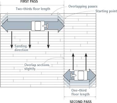
When sanding with the grain, start along a wall and sand about two-thirds the length of the

Replacing a Floorboard

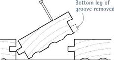
image999"image1000Подпись: Subfloor To insert a replacement board into an existing tongue-and-groove floor, use a table saw to remove the bottom of the groove. Slightly back-cut the ends of the new board so it will slide in easier. To remove a damaged board, drill holes across it so you can pry it out in splinters, using a hand chisel. Or you could cut into the damaged board by using a circular saw set to the depth of the flooring and then pry out pieces with a flat bar. To make this pocket cut, rest the heel of the saw on the floor, pull back the saw guard, and slowly lower the front of the saw sole until the turning blade engages the wood. Be careful: Holding a blade guard back is never advisable if you can avoid it, and the saw may jump when it engages the wood. Let the blade stop before you lift the saw.

Find a replacement board that’s similar in color and grain: Try to pull a board from a nearby closet or from floor section that’s usually covered by an appliance. Hold the board next to the hole and use a utility knife to mark off the appropriate length. To make the replacement fit more easily, slightly back-bevel its lower edges on a table saw. If the stock is tongue-and-groove, use a table saw to cut off the lower leg of the groove. Apply construction adhesive to the underside of the new board, and then drive it into the opening using a piece of scrap to cushion the hammer blows. It’s not possible to nail the board through its tongue, so predrill and face-nail two 6d finish nails at either end. Use a nail set to drive the nails below the surface. Fill the holes with wood putty.

Overlap Sanding Passes

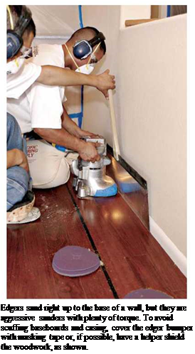
Подпись: Edgers sand right up to the base of a wall, but they are aggressive sanders with plenty of torque. To avoid scuffing baseboards and casing, cover the edger bumper with masking tape or, if possible, have a helper shield the woodwork, as shown.

image1002

Start along a wall and sand about two-thirds the floor length. Sand up and back. Then raise the drum, and roll the sander over so the next pass overlaps by roughly half a drum-width. Sand till you reach the opposite wall. Then turn the sander 180° and sand the remaining third of the floor.

SANDING FLOORS

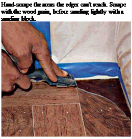
Подпись: Hand-scrape the areas the edger can't reach. Scrape with the wood grain, before sanding lightly with a sanding block.

floor. Then, with the drum lowered and sanding, pull the machine backward over the strip just sanded. Raise the sander’s drum toward the end of each backward pass and wheel the machine over about 6 in., so the next pass will overlap the first by roughly half the width of the drum.

Again, sand down about two-thirds the length of the room, and then pull the sander backward, as shown in "Overlap Sanding Passes,” above.

Continue sanding until you have reached the opposite wall (you will have sanded two-thirds of the room by then). Turn the machine 180° and start sanding the other end of the room (the third you haven’t yet sanded). Again, sand one pass up and one back. When you reach the edge of the portion already sanded, overlap it by 1 ft. or 2 ft. before starting the next pass. In this manner you can blend the sanding of the two sections of the room.

Using an edger. After completing each sanding pass with the drum sander, use the edger to sand along the perimeter of the room, as close to the base of the walls as you can get. Use the same grit sandpaper that you just used on the drum. When it’s upright, the sander disc moves in a
clockwise direction, so work from left to right, keeping the edger moving constantly to avoid scour marks. You don’t need to press down on the edger to make it work. If the edger is sanding too aggressively, switch to the next finer grit.

If it’s not sanding aggressively enough, change its sanding disks more often. Again, try to sand with the wood grain as much as possible.

Finish up by hand. Hand scraping and sanding take care of the areas the edger can’t reach, such as in corners and under cabinet toekicks. It’s hard, tedious work, but fortunately there’s not much of it. A sharp scraper will speed the job, scraping with the grain to remove the old finish. Then use a sanding block to smooth out the semicircular edger marks. (Note: If there are a lot of edger marks, use a random- orbital sander to feather them out.) Once you’ve drum-sanded, edged, and hand-scraped the room, vacuum it well before switching to the next-finer grit

DO THEY HURT A SEPTIC SYSTEM?

What about garbage disposers, do they hurt a septic system? The answers offered to this question vary from yes to maybe to no. Many people, including numerous code enforcement offices, believe garbage disposers should not be used in conjunction with septic sys­tems. Other people disagree and believe that disposers have no adverse effect on a septic system.

it is possible for the waste of a disposer to make it into the distribution pipes and drain field. If this happens, the risk for clogging is elevated. An­other argument against disposers is the increased load of solids they put on a septic tank. Obviously, the amount of solid waste will depend on the fre­quency with which the disposer is used.

What is my opinion? My opinion is that disposers increase the risk of sep­tic system failure and should not be used with such systems. However, I know of many houses using disposers with septic systems that are not experiencing any problems. If you check with your local plumbing inspector this question may become a moot point. Many local plumbing codes prevent the use of dis­posers with septic systems.

Cooking Options Pit Efficiency against Cost

More efficient cooking saves energy and money directly, of course, but by keeping waste heat out of the kitchen, it also saves on air-conditioning. Although this impact might not be huge in a typical home, it can make a difference. As a rule, electric cooking appliances are more efficient than gas-fueled ones. But the relative price of natural gas versus electricity often makes natural-gas- fueled appliances a more economical choice. Gas cooktops also afford better heat control than their electric counterparts.

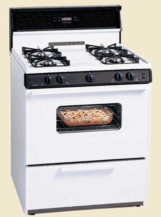
Because their functions are so different, it’s important to consider cooktops and ov­ens separately, even though they might be combined in a stand-alone kitchen range.

Gas Ovens Draw Electricity, Too

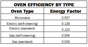
With ovens, rapid heat-up and cooldown aren’t as important as with cooktops, mak­ing electric ovens more competitive with gas, even for serious cooks. In fact, it is not uncommon for high-end ranges to have a gas cooktop and an electric oven. Again, electric models are more efficient: Electric ovens are 1.8 to 3.5 times as efficient as gas ovens, according to U. S. Department of Energy (DOE) data. Cost efficiency, however, largely depends on which type of fuel costs the least in your area.

Most gas ovens also use a lot of electric­ity while operating. In nearly all gas ovens today, when the gas burner is operating, an electric glow-bar igniter (sometimes called a "gas oven igniter") is on, drawing about 375w. (Interestingly, at a recent International Builders’ Show, not one kitchen-appliance salesperson who was asked seemed aware of this fact.) Found in all self-cleaning models, the glow bar ignites the gas when the oven is turned on and reignites it as it cycles off and on during the cooking or self-cleaning process. Those 375w (or even as much as 500w in some ovens) are a significant amount of electricity. If low electricity use is a priority in your home, consider a model without a glow bar, such as ranges made by the Peerless-Premier Appliance Co. (www. premierrange. com), which operate with a pilot or a spark ignition.

Cooktops & Ovens: Electric Wins over Gas

Cooktop efficiency is difficult to measure, and relatively little attention has been paid to it, primarily because stovetop cooking ac­counts for a small percentage of household energy use—about 5%, according to the American Council for an Energy Efficient Economy. My research shows that electric cooktops are the most efficient, and gas the worst. The section below ranks the most common cooktop technologies in order of efficiency based on the energy factor, which is the ratio of the amount of energy conveyed to an item being heated to the de­vice’s overall energy consumption. Expressed as a decimal, it reflects the proportion of energy used that actually contributes to the cooking of food.

COOKTOP TYPES

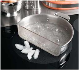
Induction Although induction technology initially failed to take off when introduced a decade or so ago, it’s back, with more high – end induction cooktops entering the market. On an induction cooktop, electrical energy is transferred directly to ferrous-metal cook­ware through magnetic induction. Efficiency is the highest of any cooktop (about 84%) because the cookware is heated directly. It’s also a safer way to cook: The cooking surface does not heat up, enabling photos like the one at top left on facing page, where water boils in a cutaway pan while ice cubes rest intact on the "burner’s" surface. Induction
Cooking Options Pit Efficiency against CostCooking Options Pit Efficiency against CostCooking Options Pit Efficiency against Cost

Подпись: iNDUCTiON Energy Factor: 0.84 ELECTRiC COiL

Energy Factor: 0.737

Cooking Options Pit Efficiency against Cost

RADiANT

Energy Factor: 0.742

cooktops also heat up and cool down quick­ly, providing precise controllability. Down­sides include high cost and the fact that on­ly certain cookware can be used. Cast-iron, enameled cast iron, and some stainless-steel cookware work. Test yours to make sure a magnet sticks to it, or look for a label.

Radiant ceramic The most common mid – to high-end electric cooktop today, it has rel­atively fast-heating radiant elements under ceramic glass, providing a sleek, easy-to-clean stovetop surface. Flat-bottom cookware is needed for good surface contact; older – style cast-iron pans are not recommended because burrs on the metal can scratch the glass surface. Radiant-ceramic cooktops heat faster than electric coils and are nearly equal in energy efficiency.

Cooking Options Pit Efficiency against Cost

GAS, NO PiLOT

Energy Factor: 0.399

GAs, piLOT

Energy Factor: 0.156

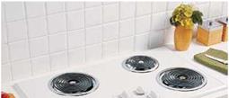
Electric coil Available on low-cost ranges and cooktops, these old-fashioned open-coil elements are slow to heat up and difficult to clean, but fairly efficient at transferring elec­tric energy to the pot.

Gas (natural or propane) Cooks prefer gas burners for speed and controllability, but indoor-air-quality experts often recommend against gas for health reasons. Although gas cooktops rate worst in terms of energy ef­ficiency, they are usually more cost-efficient because the price of natural gas is typically a lot lower than electricity. Gas cooktops use only about 40% of the energy produced, and if there’s a continuously burning pilot light, the overall efficiency is far lower (about 16%). In some areas, propane is nearly as expensive as electricity per unit of delivered

energy, making electric cooktops a more eco­Ovens and Oven Fans nomical option. The efficiency of natural gas

and propane is essentially the same.
Подпись: Self-cleaning ovens typically have more insulation than standard ovens, so if you have a choice, go for a selfcleaning model. The extra insulation keeps the outer surface of the range from becoming too hot during the self-cleaning cycle, but it also helps the oven to operate more efficiently. Oven fans Convection ovens have a fan in the back that circulates air to maintain more-even temperatures. As a result, either the cooking time or the temperature can be reduced. The energy savings from reduced gas or electricity use for cooking easily outweigh the fan's electricity use. Cooking Options Pit Efficiency against CostПодпись: OVEN EFFICIENCY BY TYPE Oven Type Energy Factor Microwave 0.557 Electric (self-cleaning) 0.138 Electric (standard) 0.122 Gas (self-cleaning) 0.054 Gas (standard) 0.030

Trick of the trade

When doing finish work (particularly when remodel­ing an older structure), carpenters often run up against crooked floors, walls, and ceilings. I’ve found that when things are out of plumb or level, it’s best to build parallel to that. The eye can see two lines that go away from each other much easier than it can see plumb or level. So, for example, if a win­dow opening is out of plumb and can’t be fixed, and if surrounding trim is parallel to the out-of-plumb
opening, go ahead and set the window slightly out of plumb too. This way the side of the window will at least run parallel with the opening and be pleasing to the eye. This is particularly true when placing a new window next to an existing window or door that isn’t exactly plumb. If the new window is perfectly plumb and level and the old one isn’t, then both of them will read as crooked.

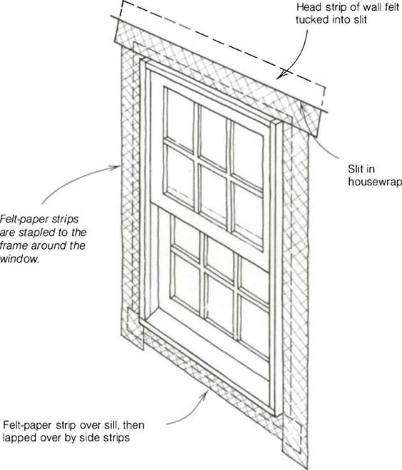
Window flashing details

Trick of the trade

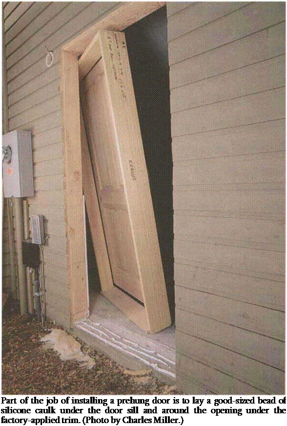
Подпись: Part of the job of installing a prehung door is to lay a good-sized bead of silicone caulk under the door sill and around the opening under the factory-applied trim. (Photo by Charles Miller.)

dow, move inside and seal the gap between the window frame and the wood framing with nonexpanding foam. Don’t use expanding foam, which can bow trimmers and frames out of shape. Then open and close the window a few times to make sure it works with ease.

Setting exterior and interior doors

We’ve all lived in houses that have doors that stick, locks that are misaligned, and hinges that creak. After years of use, doors and windows that open and close with ease indicate that the folks who built the house knew and cared about what they were doing.

The majority of doors used these days are prehung and are installed much the same way as windows (see the sidebar on p. 178). Both doors and windows can be ordered with jambs wide enough for 2×4 or 2×6 walls (see the photo at right) and are usually available with factory – applied trim. Begin installing one of these units by stapling strips of felt paper around the opening. Then apply a good-sized bead of silicone caulk under the door sill and around the opening under the factory-applied trim.

An easy place for rot to develop is under the door sill, so take extra precautions to seal this area. I get several calls a year from people who want their rotted sill or floor replaced. Lay down a couple of layers of felt paper, lapping them up the trimmers and down over the outside edge. Do the same with some 10-in. metal flashing, cutting it into place with tin snips.

With the door placed in its opening, check to see if the sill is resting flat on the floor. If the floor isn’t level, the low jamb side will have to be shimmed so that the door won’t hit the head jamb when closed. I like to cut a long, thin shim under the sill so it will have good bearing.

Take time to ensure that the door will open and close with ease. On prehung doors, there should be about a Vs-in. gap between the door and the jamb head and sides. On exterior doors, the weatherstrip should seal at the bottom without binding.

1. Check to see that the floor is level and the trim­mers are plumb.

2. Apply felt paper and caulk to exterior doors to prevent leaks.

3. Set the door frame in the opening. If the floor isn’t level, pick up a jamb leg so that the door won’t stick on the jamb head when closed.

4. Check to see that door jamb edges are flush with the face of the drywall.

5. Check that there is about a Vs-in. gap between the jambs and the door and that the door opens and closes freely.

6. Nail the hinge side first, directly to the plumb trimmer.

7. Nail the lock side to the trimmer; shim where necessary.

8. Nail through the door casings into the exte­rior wall.

9. Cross-sight so that jamb sides are parallel.

Trick of the trade

If you have a pneumatic nailer, fasten the jamb to the trimmer stud with 8d nails. Sinking the fasteners behind the weatherstrip helps to hide the nail holes.


Style and Use Determine Efficiency

WHAT TO AVOID

Style and Use Determine EfficiencyПодпись: Frugal features. The most popular features with consumers—such as automatic defrosting and through-the- door ice and water dispensers—are not always the most energy efficient. Still, Maytag®'s Ice20® refrigerator meets Energy Star requirements and is equipped with two potentially energy-saving features: an alarm that alerts homeowners to a refrigerator door left ajar and a vacation mode that saves energy by limiting automatic defrosting when the fridge isn't opened for several days.
• Through-the-door ice and water dispensers. Both the lost insulation and the additional cooling coils in a through – the-door ice and water dispenser increase electricity consumption.

Подпись:Automatic ice makers. Ice makers con­sume energy, though exactly how much is difficult to determine.

WHAT TO LOOK FOR

• The Energy Star label. The U. S. Environ­mental Protection Agency confers its En­ergy Star label on models that are at least 20% more energy efficient than the federal minimum. Shopping for this label is an easy way to be sure the refrigerator you choose is not an energy waster.

• Freezers on top or bottom. Side-by-side refrigerators use more energy.

• Manual defrost cycles. The most energy – efficient refrigerators and freezers

have manual defrost, although they can be hard to find, particularly among high – end models.

• Door alarms. Some manufacturers offer an alarm that will sound if the fridge door is left open—helping to save energy and to prevent food spoilage.

MAiNTAiNiNG HiGH PERFORMANCE

• Place fridges away from heat sources—

especially a range or oven, but also a dish­washer. Radiant heat from these appliances warms the surface of the fridge, requiring more energy to keep the inside cool. If the refrigerator must be adjacent to a heat source, provide space for air circulation.

• Clean the coils, at least annually. Dust and dirt buildup on refrigerator/freezer coils reduces the heat-exchange efficiency and makes the compressor work harder. Most refrigerators now have coils that can be accessed from the front, eliminating the need to pull the unit away from the wall.

• Turn off the condensation-control feature. Essentially, these are heating elements under the protective shell that consume energy in two ways: by using electricity to warm the outer shell and by increasing the difference in temperature across the unit’s insulation. Models with
this feature usually have a switch to turn it off; do so, unless condensation becomes a problem.

• Keep the freezer full. Frozen food serves as a thermal stabilizer that reduces the amount of on-off cycling. If you don’t have a lot of frozen food, freeze containers of water (use plastic, and allow for expan­sion as the water freezes) to take up the ex­tra space. When you need ice for a cooler, you can use these frozen containers.

• Don’t keep an extra fridge in the garage.

When you buy a new refrigerator, avoid the costly mistake of keeping the old one as a backup.