BUILDING BASICS
Fillers: Resume
Summing up:
• When designing an SMA mixture, one should not decrease the content of filler below a minimum value (defined by using a 0.063-mm sieve in
Europe or a 0.075-mm sieve in the United States). The lack of filler will be reflected in a decrease in the durability of the mix and the void content and an increase in the risk of the appearance of fat spots.
• An increased amount of filler causes higher viscosity of the mortar, which promotes resistance to deformation. But one should not use an excessive amount of filler because it is easy to overstiffen the mortar, which can lead to cracking.
• Too fine a filler can cause problems since it absorbs much of the binder and may plasticize the mix.
• It is worthwhile to take note of Rigden’s test results, particularly when changing filler in the same mixture during continuous production. A new filler with a decidedly different void content than the former one may result in unwanted surprises.
• Adding hydrated lime at a rate of about 1.0-1.5% is a good move as doing so improves the binder-aggregate adhesion and boosts resistance to water damage.
Water in the early cities
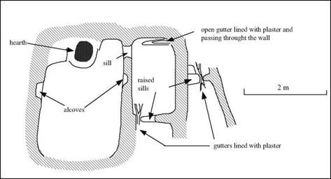
Another dimension of hydraulics appears in the early cities: that of wastewater drainage. Many medieval and modern civilizations will come to treat this problem casually, and as a result endow their cities with an atmosphere of filth. Yet the early civilizations of the East were precocious in their concern for urban drainage. Evidence of the oldest known systems for draining water from houses can be found as early as the end of the Neolithic period, around 6500 BC, at El-Kowm.[24] These comprise plaster-lined gutters dug into the ground and crossing the doorsills, as well as holes pierced through walls, and even passages below the hard surface of the ground (Figure 1.4).
Mohenjo-Daro, in the Indus valley, gives us a particularly striking example of such hydraulic works at the scale of an entire city. Here there are about 700 cylindrical wells more than 15 m deep, often located within the houses themselves. Such houses are provided with bathing rooms and often with latrines. The wastewater (including from the rooms above the ground floor) is drained through clay pipes which obliquely pass through the massive walls to connect to gutters covered with slabs, water being then conveyed into brick-covered passages dug underneath the walks between houses, and finally into larger collectors. In these drainage systems, settling basins prevent blockage by debris. In alleys and passageways that are not on the drainage system, large bottomless urns serve as cesspools.[25]
A number of the early cities of Mesopotamia, at the end of the IVth or beginning of the IIIrd millennium BC, are similarly endowed with networks of wastewater and stormwater drainage.[26] These include Habuba Kebira, Mari, Eshnunna, then Ugarit in the IInd millennium BC (see the maps of Figures 2.1 and 4.1 for the geography of these cities). At Habuba Kebira, which is a Sumerian establishment of a thousand inhabitants founded about 3500 BC and occupied for only a century and a half, various systems are used to drain wastewater. The streets, well maintained and paved with an aggregate of gravel, are equipped with U-shaped gutters made from 64-cm long sections of clay, or sometimes from conduits covered with slabs of stone, draining wastewater and stormwater outside the city walls. Even true conduits made from interlocking sections of clay pipe have been found.[27] At Mari, pipe networks whose total length can be greater than a hundred meters service multiple sanitary installations in the same house. But in Mesopotamia, this preoccupation with drainage seems to have faded away in time.
It is in Crete, in the IInd millennium BC, that we rediscover elaborate systems of water drainage – and for the first time also systems of water supply. We return to these in Chapter 4.
|
Figure 1.5 House with adjoining rooms at El-Kowm (about 6500 BC), with the remnants of drainage systems: the oldest known traces of water conveyance? (adapted from Stordeur, 1989). |
Statistical independence
If two events are statistically independent of each other, the occurrence of one event has no influence on the occurrence of the other. Therefore, events A and B are independent if and only if P (A, B) = P (A) P (B). The probability of joint occurrence of K independent events can be generalized as
![]() K
K
![]() = P(A1) X P(A2) x-.-x P(Ak) = П P(Ak)
= P(A1) X P(A2) x-.-x P(Ak) = П P(Ak)
k=1
It should be noted that the mutual exclusiveness of two events does not, in general, imply independence, and vice versa, unless one of the events is an impossible event. If the two events A and B are independent, then A, A7, B, and B’ all are independent, but not necessarily mutually exclusive, events.
Example 2.2 Referring to Example 2.1, the probabilities that tributaries 1 and 2 overflow during a major storm event are 0.5 and 0.4, respectively. For simplicity, assume that the occurrences of overflowing in the two tributaries are independent of each other. Determine the probability of at least one tributary overflowing in a major storm event.
Solution Use the same definitions for events E1 and E2. The problem is to determine P(E1 U E2) by
P(E1 U E2) = P(E1) + P(E2) – P(E1, E2)
Note that in this example the probability of joint occurrences of both tributaries overflowing, that is, P(E1, E2), is not given directly by the problem statement, as in Example 2.1. However, it can be determined from knowing that the occurrences of
overflows in the tributaries are independent events, according to Eq. (2.5), as
P(Ex, E2) = P(E1)P(E2) = (0.5)(0.4) = 0.2
Then the probability that at least one tributary would overflow during a major storm event is
P(Ei U E2) = P(Ei) + P(E2) – P(Ex, E2) = 0.5 + 0.4 – 0.2 = 0.7
Triangle Perimeters
Triangle perimeters are not difficult to establish. The process is similar to the one used with squares, only there is one less measurement. To find the perimeter of a triangle, add up the sum total of the three sides of the shape. if you want a formula to use, it could look like this: P = A + B + C. The long and the short of it, no pun intended, is that you simply add up the three dimensions and you have the perimeter.
Circles
Circles can give you some trouble when you are looking for their perimeters, which should really be called their circumference. I have provided resource tables in the next chapter that will help you to avoid doing the math to find the circumference of a circle, but we should at least take a few moments to
|
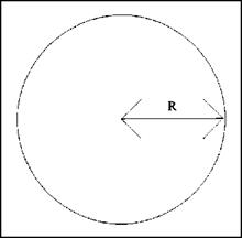
FIGURE 1.15 ■ Radius of a circle. |
|
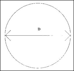
FIGURE 1.16 ■ Diameter of a circle. |
explore the procedure while we are here. Circles can be tricky, but they aren’t really all that tough. Let’s look at a couple of formulas that you shouldn’t experience problems with (Fig. 1.16).
When you want to find the circumference of a circle, you must work with the diameter (D), the radius (R), and л, which is 3.1416. You can use one of two formulas to solve your problem, depending on which variable is known. If you know the diameter, use the following formula: C = л d. When you know the radius, use this formula: C = 2лг. If the diameter is six inches, your formula would reveal that pi (3.1416) times 6 inches equals 18.8496 inches. This number would be rounded to 18.85 inches. If you knew the radius and not the diameter, your numbers would be 2 times л (3.1416) times 3 inches. The same answer would be arrived at, for a circumference of 18.85 inches. The formulas are not difficult, but using the tables in the next chapter might be faster and easier for you.
Waste Material Generated
Waste material can be categorized as construction wastes, industrial wastes, mining or mineral wastes, agricultural wastes, or domestic wastes (of which scrap tires are a significant subset). Many advanced recycling programs have been established to make use of these wastes, such as requiring identifying codes for the base resin in plastic products to enable more refined recycling of plastics. Some of these wastes are not suitable for or do not make a significant recycling contribution to highway use. For example, only a small amount of the total crop waste (estimated to be about 9 percent of all the total nonhazardous solid waste generated each year in the United States) has a beneficial highway use. Potential uses are as an asphalt extender or portland cement additive.
In another example, it has been shown that wastes can be rendered essentially benign when used in asphaltic concrete installations. In a demonstration to the Minnesota Department of Transportation, the toxicity of bottom ash from a municipal sewage sludge incinerator was shown to be less than or equal to the toxicity of the asphaltic concrete matrix to which it was attached (Request for Approval of WIA in MnDOT Asphaltic Concrete Non-Wear Course Projects, Final report, S. David, Jan 16, 2002).
The following articles contain brief descriptions of the types of wastes that research has indicated have the potential for use in highway projects (NCHRP Synthesis 199).
Legal Considerations
1.12.1 National and Trans-National
The demands of legislation can greatly influence the design and management of a road in order to control its influence on the water environment. General legislation, such as European directives (e. g. the Water Framework Directive), define water protection in a general manner with universal requirements that no pollutant input is allowed and that high cleanliness of water bodies should be established. However valid legislation at a national level, or even locally valid ordinances, can precisely define such requirements in terms of the level and manner of these protection measures. The level of the protective prescriptions depends on the legal system. In some countries the valid legislation is very general repeating obligations from the European directives and the proper implementation and then the functioning of protection measures are the responsibility of the road owner, operator and the designer. In some other cases, protection is very precisely defined by technical legislation that has been mandated centrally. In these kinds of document all the technical details can be found.
During the development of a road scheme, existing hydrological and hydrogeological zones, crossed by road, are classified on the basis of legally existing water protection zones (e. g. drinking water source protection zones, Natura 2000 zones) and natural field conditions encountered. As a first step, desk studies are performed to define the demands and requirements for each section of the road consequent upon the legislation. Similar sections are then grouped together and field investigations undertaken to gather representative information on each group. Results of the field investigations are used to determine the specific level of water protection that is required. If the particular requirements defined in any existing protection ordinances are not as strict as those obtained as a consequence of the investigations performed during the scheme development, technical protection measurements must be adopted to ensure that the water body is protected according to the natural conditions that have now been revealed. If prescribed demands in the ordinances are stricter than established by field investigations, the protection requirements are retained and usually the designer does not oppose them. The designer would need to be certain that every section within the group of sections being analysed was less susceptible to degradation. Even then, the time taken to get the water protection zones re-classified to a lower risk category will often be longer than the time taken to commence construction, negating the benefit that might otherwise accrue to the road scheme.
Among locally – and state-valid legislation, constraints to road construction and operation are usually defined in ordinances defining drinking water source protection zones. They are defined as requirements, prohibitions and restrictions and they can be grouped in the following way:
• restrictions on areas for construction of roads and manoeuvring areas;
• technical engineering requirements for the protection of groundwater (e. g. runoff collection / safety bunds / soakaways / pipe integrity);
• traffic speed restrictions, restrictions of certain traffic types;
• management control measures (e. g. cleanliness of drainage facilities, controlled disposal of plant cuttings, periodic water sampling, etc.);
• restrictions of transport of certain dangerous and harmful substances; and
• demands regarding the setting up of road signs in protected areas.
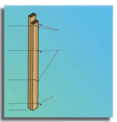
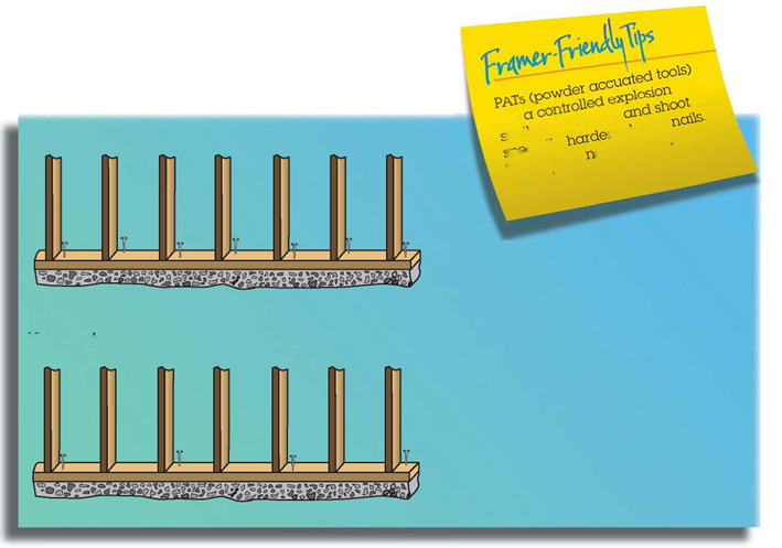
Nail Bottom Plate to Studs

|
|
|
|
|
|
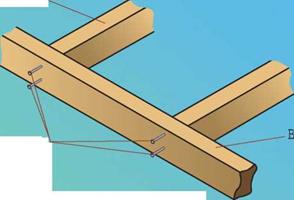

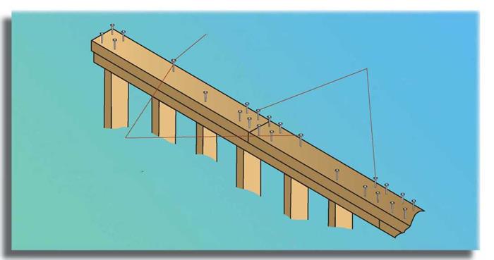 Nail Double Plate to Top Plate
One 16d nail at 16" O. C, (on center) or one 3" x,131" nail at 12" O. C, Stagger nails,
Four 16d common nails or six 3" x,131" nails each side of splice in top and double plate,
Nail over studs to allow plumber’s and electrician’s drills to pass freely through the place between the studs
Two 3” x,131" nails at 16” O. C. may be substituted to prevent interference,


![]()
 Nail Walls Together or Nail Double Studs
Five 16d (3 1/2" x,135") nails or twelve 3" x,131" nails into studs, Start 6" from top and bottom,

 Note: A 16d (3 1/2" x,135") nail will protrude 1/2" beyond a doubled 2x, This sharp nail point can be a hazard, Nail at slight angle to prevent protrusion,
![]()
![]()
 |
||
![]()
 |
PLUMB AND LEVEL
A plumb bob takes patience to use, but it’s a compact, accurate tool. The plumbed string is also a useful reference line you can measure out from. The Gammon Reel® shown in the photo on the next page automatically reels in the string so it can’t tangle up in a tool pouch.
A 4-ft. spirit level is a good, all-purpose level, long enough to level accurately across joists, check for level and plumb of door and window casings, and so on.
A 2-ft. spirit level enables you to level window sills, door head jambs, and other tight spaces where a 4-ft. level won’t fit.
A standard torpedo level is small and fits into a tool pouch. Though it’s not as accurate as a longer level, it’s good for a quick reference in

![]()


tight spaces. Magnetic versions can stick to cast – iron pipe.
A torpedo level with a laser has the same limitations as any torpedo level, but its laser allows plumbers to set the tool on a pipe that’s pitched correctly and extend that pitch (indefinitely) to other pipe sections.
Circular saws are generally characterized as either worm-drives or sidewinders and are often called Skilsaws®, the name of a popular brand.
Among professional builders, especially on the West Coast, worm-drive circular saws are favored for cutting framing lumber. They tend to have bigger motors and more torque. They also spin slower, bind less, and run quieter than sidewinders. If you’re right-handed, worm-drive saws make it easier to see the line you’re cutting.
Sidewinders are generally lighter and more compact, so they’re easier to handle and a good choice for the occasional builder. But because the blade is turning at 90° to the motor shaft, it is more likely to bind if your cut wanders off the line. For that reason, a rip fence is a nice accessory.
Beam saws are called "sidewinders on steroids” because they can accommodate 10-in. blades that cut smoothly through 4x lumber in one pass. It’s not a must-buy item, but wow, what a tool!
For circular-saw blades in general, the more teeth, the smoother the cut. If you buy just one, make it carbide tipped; it will stay sharp far longer and give cleaner cuts. There are specialty blades for almost anything you’d want to cut: tile, concrete, metal, and wet or pressure-treated lumber (has a Teflon™ coating). Remodelers’ blades cut through wood and the occasional nail without being damaged.
A reciprocating saw, also called a Sawzall® after a popular make, is the indispensable demolition saw. A marvel in tight spaces, it can remove old pipes, cut through studs or joists or, with a bimetal blade, cut through nails and studs in one pass. (Blades break, so get extras.) A “recip” saw is also useful in new construction to notch studs for pipes, cut plywood nailed over rough openings for windows and doors, and so on.
Jigsaws, sometimes called saber saws, are useful for notches, curving cuts, and odd-shaped holes. Typical uses include cutting out holes for sinks in countertops and holes in cabinet backs so pipes or ducts can pass through. The blades are thin and prone to snap, so buy extras.
Climate and Climate Change
The ultimate reason for having drainage is because of rain! Therefore the drainage needs and solutions will be heavily influenced by the climate where the road is built. Broadly, climate may be divided by temperature and by rain/snowfall. Typically climatologists further differentiate on temperature variation across the year and on rainfall distribution. A very commonly used classification that takes this approach is that due to Koeppen (McKnight and Hess, 2000). This divides the world into 5 major zones, each with subdivisions:
• Tropical – subdivided into Rain Forest, Monsoon and Savannah;
• Dry – subdivided into Desert and Steppe;
• Temperate – subdivided into Mediterranean, Sub-tropical, Maritime and Maritime Sub-polar;
• Continental – subdivided into Hot Summer, Warm Summer and Sub-arctic; and
• Polar – subdivided into Tundra and Ice-cap. Alpine climates can be grouped here, too, although their climate results from elevation, not latitude.
The characteristics of each climate will have major effects on the water in the road and adjacent ground. In particular, where the potential for evaporation is
|
Fig. 1.12 Simplified climatic zone map of Europe. 1 – Temperate, maritime; 2 – Temperate, Mediterranean; 3 – Continental, warm summer; 4 – Dry, steppe; 5 – Temperate, sub-tropical; 6 – Alpine; 7 – Continental, sub-arctic; 8 – Polar, undifferentiated |
significantly greater than rainfall, the effects of drainage may be less noticeable. However, this would need to be true throughout the year. Thus in tropical monsoon climates it may be true averaged over the year, but it is certainly not true during the wet season. It is at such a time that effective drainage may make the difference between survival of the road and its rapid deterioration.
Figure 1.12 shows a schematic division of Europe into the appropriate climatic zones.
In recent years the topic of climate change has become a consideration for almost everyone and road builders and operators are no exception. Temperature rise itself is unlikely to make a lot of difference to water in road structures in the warmer temperate areas, but in areas with seasonal freezing it could make a big difference. If the seasonal freeze period is reduced in length or lost or occurs repeatedly with intermittent thaw periods, then much longer periods of wet, non-frozen conditions (as currently experienced for shorter periods in the Autumn and Spring) can be expected, necessitating more stringent drainage requirements and causing much more frequent thaw-weakening problems. However, the shorter frozen period and the shallower penetration of the freezing front into the ground means that drainage trenches should more easily continue to operate year round.
Of likely importance to almost everyone is the increased rainfall that can be expected. Warmer ocean temperatures will lead to higher amounts of water in the atmosphere and, thus, more rain and snow. Whether this water will come regularly or in a few, but more severe, storms is less certain and the answer may vary by locality. The exact result may be difficult to predict, but the urgency for keeping water out of the pavement and associated highway earthworks can only increase. With greater runoff volumes anticipated, the need to provide positive drainage increases commensurately. Below ground it would be wise to anticipate greater volumetric flow rates of longer duration than previously experienced.


