Drainability

Broadly graded aggregates, as typically used in granular base and sub-base layers of the road construction have relatively small pores as the large pores between the coarser particles are mostly filled with smaller particles. This means that coefficient of permeability values, as characterised by the Darcy coefficient, K, are relatively low. Laboratory testing of typical sub-base aggregates has revealed hydraulic con­ductivity values that are usually less than 10-3 m/s in the unlikely even of saturation (Jones and Jones, 1989) and as low as an effective value of 10-6 m/s when, more normally, in a partially saturated state.

Подпись: Fig. 2.12 Typical moisture profile with height for a compacted column specimen with water provision at the base (adapted from Jessep, 1998)
Drainability

A second implication is that the pores will have a measurable suction ability. Hence dryer aggregates will usually show an ability to pull water towards them. There is a draft CEN standard (1999) for the evaluation of the suction height (i. e. of matric potential which is an indirect measure of the suction capacity of the aggre­gate). Figure 2.12 shows a result obtained by a similar method in which a column of

Measurement Techniques for Water Flow

SigurSur Erlingsson[4], Susanne Baltzer, Jose Baena and Gunnar Bjarnason

Abstract The chapter describes different measurement techniques for water-flow – related phenomena in pavements and embankments, i. e. water content, permeability and suction. For estimating the water content the gravimetric method is described as well as non-destructive methods such as neutron scattering, time domain reflectom – etry and ground penetrating radar. Then methods for estimating both the saturated and the unsaturated permeability of soils and granular materials are described. Both steady-state and unsteady methods are mentioned. Finally, common methods for measuring soil suction are briefly introduced.

Keywords Water flow ■ measurements ■ water content ■ permeability ■ suction

3.1 Introduction

Water entering a pavement structure migrates as moisture through the structure. The amount of water penetrating the pavement is dependent on precipitation, drainage, design of the road structure, type and condition of the surface layer (cracks, joints) and shoulders and the materials in the pavement, subgrade and subsoil. Seasonal fluctuations in temperature, i. e. freezing and thawing, can also provoke moisture flow inside the pavement structure. An excess of water can cause a lower bear­ing capacity of the pavement structure and reduces pavement life (see Chapters 8 and 10). Also of concern is transport of contaminants with the liquid fluxes from the road and into the environment (see Chapter 6). As pavement deterioration can be reduced by proper drainage it is important to be able to measure the water content in order to understand how water moves within the road structure.

Predictions of water flow and contaminant transport in unsaturated soils should be based on an accurate description of the subsurface conditions including the aggregates

and hydrological properties of the materials involved. Therefore measurements of the fundamental parameters regarding flux of water need to be carried out. This also helps to set the initial conditions for analysis in water flow modelling.

The most important parameters related to the movement of water through pave­ment structures are the quantity and spatial distributions of moisture inside the pave­ment, the coefficient of permeability of individual layers and their matric suctions. These parameters can be determined experimentally, either in the field or in the laboratory, by various techniques. The most common of these methods used in road engineering will be briefly described in this chapter.

STEP4 Attach the Sills

Some important carpentry work is about to begin. Whether you are building on a concrete slab, over a crawl space, or over a full base­ment, the first wooden member that is laid down is called a sill, mudsill, or sole plate.

T his sill is commonly a pressure-treated 2×4 or 2×6 attached directly to the foundation with anchor bolts embedded in the concrete. Occasionally, it is attached with hardened concrete nails or steel pins shot through the sill and into the concrete by a powder – actuated nailer.

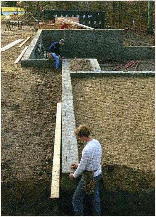
Подпись: SNAP CHALKLINES TO LAY OUT THE SILL. The line shows where the sill's inside edge rests. If the foundation isn't perfectly square, adjust the line's position so that the sills will be. [Photo by Roe A. Osborn, courtesy Fine Homebuilding magazine, The Taunton Press, Inc.] STEP4 Attach the SillsMost codes require that anchor bolts be located I ft. from each corner of the founda­tion, 1 ft. from the ends of each sill plate, and a maximum of 6 ft. o. c. everywhere else. These are minimum requirements. Builders living in earthquake or high-wind areas often use %-in.-dia. anchor holts rather than /Tin. bolts and reduce the spacing to 4 ft. o. c. or less. As mentioned in chapter l, its important to check with the local building inspector to ensure that the house you’re building meets or exceeds code.

Check the foundation first

Unfortunately, you can’t assume that your foun­dation is straight, parallel, square, and level.

STEP4 Attach the Sills

30-20-10 rule

The 30-20-10 rule suggests that proper stone-to-stone contact is created if the per­centages of aggregate passing sieves of 0.075 mm, 2.36 mm, and 4.75 mm equal 10%, 20%, and 30%, respectively, which should provide for the appropriate discontinuity in the gradation. After comparing this rule with the data of Table 6.4, one can see that the proportion of grains larger than 4.75 mm from this rule (70%, or 30% passing the

TABLE 6.4

Approximate Contents of Aggregate Fractions for Zichner’s Mastimac and Mastiphalt

Filler Fraction

sand Fraction

Aggregate

Aggregate

Aggregate

mixture

< 0.09 mm

0.09-2.0 mm

2/5.6 mm

5.6/8 mm

8/12.5 mm

MASTIMAC

12-13%

11-12%

15%

60%

(SMA 0/8) MASTIPHALT

12-13%

11-12%

10%

27%

38%

(SMA 0/12.5)

Source: Based on Zichner, G., MASTIMAC unad MASTIPHALT bituminose Gemische fur hochwer – tige Deckschichten. STRABAG Schriftenreihe 8, Folge 4, 1972.

30-20-10 rule Подпись: Coarse grains continuous matrix, no sand

FIGURE 6.1 Relationship between contents of voids in the aggregate mix and the coarse aggregate fraction. (Based on Ferguson, A., Fordyce, D., and Khweir, K., Proceeding of the Third European Symposium on Performance and durability of bituminous Material and Hydraulic Stabilised Composites, AEDIFCATIO publishers, D-79104 Freiburg i. Br. and CH-8103 Unterengstringen/Zurich, 1999; Francken, L. and Vanelstraete, A., Proceeding of Eurobitume Congress Stockholm, Sweden, 1993; Lees, G., Journal of the Association of Asphalt Paving Technologists, 39, 1969; van de Ven, M. F.C., Voskuilen, J. L.M., and Tolman, F., The Spatial approach of hot mix asphalt. Proceedings of the 6th RILEM Symposium PTEBM’03, Zurich 2003.

each other (a skeleton of coarse grains has been formed and is filled with fine grains); the replacement phase has come to an end.

• Then follows the reverse direction of changes in the contents of voids—the mixture becomes open by means of gradually removing the fine aggregate among coarse grains up to 100% (m/m) coarse aggregate when the highest content of voids is reached; that process could be named the filling phase.

The aforementioned relationship between the amount of air voids and gradation of the coarse aggregate fraction directly translates into the binder content in SMA (Druschner and Harders, 2000; Schroeder and Kluge, 1992). The difference in the binder content, which is dependent on the content of grains larger than 2 mm, has been proved in the previously mentioned German publications (and many others pub­lished in Germany). In these examples of tested SMA mixes, the optimum binder con­tent in an SMA mixture depended on the coarse fraction content. For example, with 73% (m/m) of coarse particles content and air voids at the level of 3% (v/v), the binder content amounts to 5.5% (m/m); after an adjustment of the aggregate mix and an increase in the content of coarse aggregate up to 80% (m/m), the same 3% (v/v) of air voids are achieved at a binder content of about 7% (m/m). These results were achieved with the use of a Marshall hammer with a compaction effort of 2 x 50 strokes.

This relationship among contents of binder, air voids, and the coarse aggregate fraction establishes a rule that the content of voids in a designed SMA mixture should not be adjusted by changing the binder content. There is a much higher potential for changing the air voids by adjusting the content and gradation of the coarse aggregate fraction or, generally, by altering the gradation curve.

How an MSDS Can Be a Useful Tool

Although the MSDS has shortcomings, it is still an important tool for people involved in construction. If you are not working with a physician/architect team knowledgeable about chemicals, the MSDS can be confusing to interpret. However, the MSDS may provide useful information when used in conjunc­tion with other tools. The National Institutes of Healths National Library of Medicine has developed a searchable database for a wide variety of household product information.5 The database can be searched by product, in­gredients, and MSDS. By comparing MSDS chemical lists with the information available through the library, it is possible to gain a bet­ter understanding of recognized potential hazards for the listed chemicals.

Certain rules of thumb can also be used to evaluate a chemical listed in the MSDS. For example, if no special precautions are re­quired when using the chemical, if there are no listed health effects, and if cleanup in­volves only water, you might assume that the chemical in question has relatively low toxic­ity. On the other hand, if it is recommended that you wear gloves and goggles and use a respirator in a well-ventilated area, the prod­uct is likely a health hazard at least while being applied, though it may not have detrimen­tal health effects once fully cured. Certain chemicals should pique your concern, such as chlorinated or fluorinated compounds and chemicals that contain toxins such as tolu­ene, phenol, benzene, xylene, styrene, formal­dehyde, and the heavy metals, to name just a few.

With more than 88,000 chemicals in com­mon use and no toxicity data on most of them, our evaluation can be only partial at best. The US Environmental Protection Agency has published a list of 53 chemicals that ranked highest as persistent, bioaccumulative, and toxic compounds, or PBTs.6 The California Of­fice of Environmental Health Hazard Assess­ment has published a list of chronic exposure levels for 80 common chemicals.7 Lists such as these are far from comprehensive and they cannot help us choose products with certainty. They can, however, help us to identify known hazardous chemicals and exposure levels and to reject products that contain these.

In summary, although you cannot base your decisions solely on information from the MSDS, it is nevertheless useful. Below are two MSDS examples, with product and manufac­turer names omitted. Because MSDSs do not always follow a consistent format, compari­sons can be difficult. Section numbers will vary, but the information covered remains the same. While the MSDS for Product #1 is in­dicative of a product that may be safe to use and in fact is one we recommend to our cli­ents, Product #2 has an MSDS that provides cause for concern.

Product Identification

This section includes the name of the prod­uct, the manufacturer, the date the MSDS was prepared, and the preparer s name. In the first sample MSDS, the product is a wood pres­ervative. The second sample involves a foam insulation material. As seen in the examples, product information may range from very lit­tle to substantial.

Material Safety Data Sheet

Section 1 -— Product Identity

Manufacturer’s Name:

Date Prepared:

Preparer’s Name:

Chemical Name: Water-based wood preservative

Product:

Chemical Formula: N/A (product is a mixture)

Product Identification No.:

DOT Shipping Class: Not regulated

Emergency Telephone Number:

Product # 2 TABLE 1.2

Material Safety Data Sheet

Manufacturer:

Date Prepared:

Telephone Numbers:

Emergency Number:

Technical Information:

Regular Business Hours:

Material Identification and Hazardous Components This section lists the chemical names of all product ingredients found to be reportable health hazards. Exposure limits in some in­stances are established by government agen­cies. As discussed earlier, OSHA PEL refers to the permissible exposure limits set by OSHA and ACGIH TLV refers to the threshold limit values set by the American Conference of Governmental Industrial Hygienists. These values are updated on a regular basis.

If you are not familiar with the toxicity of the chemicals listed and you have no refer­ences available on the subject, you can infer this information by examining the limits set by the government. When the limit is in parts per million, you can be sure that the product is highly toxic. NE stands for no established limit, and could mean either that adequate testing has not been performed or that the product is not considered highly toxic.

With a health rating of і, flammability and reactivity levels of o, and no established expo­sure limits, we can assume that the ingredients in this product are relatively safe.

In the second sample MSDS, the chemi­cals 4,4-diphenylmethane diisocyanate and chlorodifluoromethane (HCFC-22) are lim­ited to parts per million. Both chemicals are in fact known to be extremely toxic. With pro­longed or repeated exposure, diisocyanates and halogenated hydrocarbons can damage

Section II — Hazardous Ingredients

Hazardous Components (Special Chemical Identity/Common Names)*

CAS#

Wt. %

OSHA PEL

ACGIHTLV

Propylene glycol

57-55-6

30-50

None established

None established

Polyethylene glycol

25322-68-3

30-50

None established

None established

Disodium octaborate tetrahydrate

12008-91-2

20-30

15 mg/m3 (dust)

10 mg/m3 (dust)

* Denotes a toxic chemical reportable under SARA Title 111 Section 313, Supplier Notification provision HMIS Information: Health:!; Flammability: 0; Reactivity: 0

Product #2 TABLE 1.4

Section II — Hazardous Ingredients/ldentity Information

CHEMICAL NAME

CAS NO.

OSHA PEL

ACGIHTLV

PERCENTAGE

Polyurethane resin

NE*

NE*

NE*

50-85

4,4-diphenylmethane diisocyanate

101-68-8

0.02 ppm CEIL

0.005 ppm TWA**

5-15

Chlorodifluoromethane (HCFC-22)

75-45-8

1,000 ppm TWA**

1,000 ppm TWA**

15-25

*Not established **Time-weighted average Hazard Rating: Health: 3; Flammability: 0; Reactivity:!

the nervous, immune, and endocrine systems. Note that the health hazard rating is 3 out of a possible 4.

Roof Flashing

Because underlayment directs water away from sheathing, it’s technically flashing, too. More often, however, roof flashing refers to sheet metal that protects building seams or edges from water penetration or diverts water around pipes, chim­neys, dormers, and so on. Metal flashing is widely used because it’s durable and relatively easy to cut and shape. Always replace old flashing when installing a new roof.

MATERIALS

Various sheet materials are suitable for flashing. Unformed, they come in sheets 10 ft. long or in rolls of varying lengths, widths, and gauges. Copper is the longest lasting and most expensive. Lead is the most malleable but is also the most vulnerable to tears and punctures. Galvanized steel ranks second in longevity, but it’s so rigid that you should buy it preshaped or rent a metal­bending brake to use on site. Lightweight alu­minum is commonly shaped on site and is a good trade-off in expense and durability. There’s also painted steel flashing, in case you don’t like the glare of bare metal.

When installing flashing, use the fewest nails possible and avoid nailing in the center of a flash­ing channel, where water runs. If possible, always position nails so they can be overlapped by roofing above. Where you must leave nail heads exposed—say, when installing skylight flashing or wall cap-flashing—put urethane caulk under the nail heads before driving them down or use gasketed roofing nails.

DRIP-EDGE FLASHING

You want water to drip free from roof edges, rather than being drawn by capillary action back up under shingles or sheathing. Drip-edge also covers and protects sheathing edges from gutter splashback and ice dams along the eaves and gives rake edges a clean, finished look. The

ACTION

A number of metals, if paired, will corrode one another in a process called galvanic action. To be safe, use nails or clips that are the same metal as the flashing you install. Because water is an electrolyte, any moisture present will increase corrosion. The following metals make up a group known as the electrolytic sequence.

image141

When you pair up materials, the metal with the lower number will corrode faster. If you must pair two different metals, you can retard galvan­ic action by insulating between the metals with a layer of heavy (30-lb.) building paper.

Подпись:image143Подпись: Underlayment runs over the eaves drip-edge, and rake drip-edge runs over the underlayment. Thus, at lower corners the rake drip- edge will overlay the eaves drip-edge.crimped edge of drip-edge flashing also resists bending and thus supports overhanging shingles.

Drip-edge is sold in varying widths and comes in an L-shape or a lopsided T-shape. Install drip – edge along the eaves first, nailing it directly to sheathing, using 4d big-head roofing nails. Space nails every 18 in. or so. Underlayment along the eaves thus overlaps the drip-edges. Along the rake edges of a roof, install underlayment before applying rake drip-edge. In the corners, where rake edges meet eaves, run the rake drip-edge over the eaves drip-edge. Slitting the vertical leg of the rake drip-edge makes it easier for you to bend it over the leg of the eaves drip-edge.

In general, drip-edge flashing 6 in. wide or wider is better than narrower flashing because it enables you to nail well back from the edge of the flashing—always desirable.

Establishing Access Control

Access control may be exercised and established by statute—through zoning ordinances, driveway controls, and turning and parking regulations—and by geometric design. Control by statute is used where full access control or a high degree of access control is required. Direct driveway connections may be prohibited, and at-grade intersections may be allowed only with major crossroads. This may be employed for a major urban arterial.

Zoning can control the type of property development adjacent to the roadway, and thereby influence the amount and type of traffic generated in the area. Property uses can be limited to those that attract very few people, excluding those that would generate significant volumes of traffic during hours of peak movement. Zoning regulations can require off-street parking provisions as a condition for permit approval.

Driveway controls can be effective in preserving the functional character of the roadway. On arterials in built-up urban areas, it is important to establish minimum spacing requirements for driveways, as well as the minimum distance from a driveway to the nearest intersection.

An example of geometric design to control access is the use of a frontage road to provide indirect access of abutting properties to a major arterial. Also, the use of a raised concrete median strip in the center of the road can effectively prohibit left turns into or out of driveways.

ACCESS TO PUBLIC ROADS

2.9.1 Defining Access Control

Control of access is the condition where the right of owners or occupants of abutting land to access a highway is fully or partially controlled by public authority. Access control is usually defined by regulations of the authority having jurisdiction over the roadway. The purpose of establishing access control is to provide for the safe and expeditious movement of vehicles on the street or highway, while upgrading the level of service and safety to those living near and using the facility. Regulations may be categorized as full control of access, partial control of access, and driveway and approach regulations.

Full control of access is the means by which preference is given to through traffic by providing access connections only at selected public roads and by prohibiting at – grade crossings and direct private driveway connections. Partial control of access still gives preference to through traffic, but allows some at-grade crossings and some drive­way connections. Driveway or approach regulations may apply where no control of access is obtained. Each abutting property is permitted access to the street or highway, but the location, number, and geometrics of the access points may be governed by the regulations.

Permeability in Unsaturated Soil

Water flow in unsaturated soils is primarily dependent on the volumetric water con­tent, matric suction and on the gravitational potential. Due to the presence of air within part of the pores, water movements are obstructed and flow is only achieved through the finer pores or in films around the soil particles. The permeability (or “hydraulic conductivity”) of unsaturated soils is, therefore, reduced compared with fully saturated soils due to the presence of air in the porous media. Usually the permeability of unsaturated soils is given as the water-relative permeability defined as the ratio of the permeability at a specific water content to its permeability under fully saturated conditions, thus:

K w (в)

krw (в) = – W (2.35)

K

where krw (в) is the water-relative permeability, Kw (в) is the water permeability – both being functions of the volumetric water content, в – while K is the saturated coefficient of permeability. Brooks and Corey (1964,1966) suggested that the water – relative permeability could be estimated as

krw (в) = 0V+ v (2.36)

Permeability in Unsaturated Soil

where X is a the pore size distribution index and & is the normalized water content. Based on Mualem’s model (Mualem, 1976) van Genuchten (1980) expressed the water-relative permeability as:

Suction [cm] Vol. water content

Fig. 2.11 Water-relative permeability for a coarse (unbroken line) and fine grained (dotted line, mostly to the right in each figure) soil using van Genuchten’s equation. The parameters used to plot the curves are given in Table 2.2
where M is the same experimental parameter as given in the van Genuchten’s SWCC.

Figure 2.11 shows clearly that the permeability of a porous medium varies sig­nificantly with the suction or the volumetric water content (or degree of saturation as Sr = в/n). A reduction in the degree of saturation from fully saturated soil to 80% results in a relative permeability of only 36% of the saturated permeability for the sand and 18% for the clay respectively in the above figure. Hence, modelling water movements in pavement structures needs to address this to obtain a realistic movement of the water flow.

UNDERLAYMENT

Once limited to building paper, underlayment now includes self-adhering rubberized sheets that replace metal flashing in some cases. Thus you can base your choice of underlayment on climate, composition, and position on the roof.

Weather-resistant underlayment. Traditionally, underlayment has been 36-in.-wide, 15-lb. or 30-lb. felt paper used as a weather-resistant layer with several purposes. It keeps sheathing dry till shingles are installed, serves as a backup layer when water gets under shingles or flashing, and separates sheathing and shingles and so prolongs shingle life. (Without underlayment, shingle asphalt can leech into wood sheathing, or resins in sheathing can degrade the shingle.) Heavy – duty, 30-lb. felt paper is often specified in high – wear, high-water areas such as eaves and valleys. A standard roll of 3-ft.-wide, 15-lb. felt paper covers roughly 400 sq. ft.; the same-size roll of 3-ft.-wide, 30-lb. paper covers only 200 sq. ft. because it’s roughly twice as thick.

Because unreinforced lighter grades of build­ing paper (15 lb.) tear easily and wrinkle when wet, some types are now reinforced with fiber­glass. Moreover, all asphalt-impregnated building papers dry out and become less water resistant when exposed to sunlight, so the sooner they’re covered by shingles, the better. Building paper was never intended to be an exterior membrane.

When installing building paper on a sloped roof, have a helper and work from the bottom up. As you roll the paper out, it will tend to slide down the roof, so be sure to unroll it straight across the roof. The first course of paper should overlap a metal drip-edge nailed along the eaves. Align the paper’s lower edge to the lower metal edge and unroll the paper, stapling as you go. Staples are only a temporary attacher, to help you keep the paper from bunching or sliding. Then nail the underlayment, using the tabbed roofing nails (also called Simplex® nails) shown on p. 57. Along roof edges and where the ends of the build­ing paper overlap, space nails every 6 in., inset­ting them 1 in. from the edge. Elsewhere, drive nails in a zigzag pattern, spacing them 12 in. to 15 in. apart.

For steep-slope roofs (4-in-12 or steeper), overlap horizontal courses of building paper 2 in.

Overlap ends of seams (end laps) at least 6 in. To prevent water backup on low-slope roofs (less than 4-in-12), building codes often specify two plies of 36-in.-wide underlayment, with horizontal seams overlapped at least 19 in. and (vertical) end seams overlapped 12 in. Check your local code to be sure, for it may also specify self – sticking waterproof shingle underlayment along the eaves.

If you’re installing wood shakes or slate, use shake liner: 18-in.-wide rolls of 30-lb. building paper alternated between roofing courses.

Waterproof shingle underlayment (WSU).

WSU is a heavy peel-and-stick bituminous mem­brane that protects roof areas most likely to leak because of concentrated water flows in valleys, ice dams at eaves, or high winds at eaves and rake edges. Many building codes also specify WSU in lieu of building paper where asphalt shingles are installed on low-slope roofs. In addition to being self-adhering, WSU also self-seals around nails, making it a truly waterproof membrane.

Подпись: TIPПодпись: As you prepare to install roofing components, imagine rainwater running down the roof. To prevent water's running underneath underlayment, flashing, or shingles, roofing materials upslope must always overlay those below. 1111 Installing WSU along valleys is vastly easier and superior to lining them with unwieldy roll roofing or aluminum flashing. And with WSU,

Подпись: Tack one side of the WSU to the sheathing, fold it in half lengthwise, and then peel off the release sheet for that half. Roll out the untacked half, smoothing it from the valley outward. Pull free the stapled half and repeat. Подпись: PROnP Some WSU membranes may be degraded by petroleum-based roofing cements. If you need to caulk near WSU, urethane caulks are probably the best choice; but check your WSU installation specs to be sure. 1111 image140there’s no need to trowel on 3-ft.-wide swaths of roofing cement between 30-lb. building-paper layers to protect eaves from ice-dam damage. Snap a chalkline to position the WSU. Then unroll and cut the membrane to length, align it to the chalkline, peel off its release-sheet backing, and press the material down. Most manufactur­ers recommend rolling it once it’s down.

WSU is more easily installed with two people, but if you’re working alone, fold the WSU in half, lengthwise, and temporarily staple one edge of the membrane to a chalked guideline. Peel off the release-backing from the unstapled half of the WSU, and flop the adhesive side of the mem­brane over onto the sheathing. Finally, yank free the stapled edge, peel off the backing from the second half, and stick it to the sheathing.

Because WSU is self-adhering, you needn’t nail it; you need to use staples only to keep the sheet from sliding around before sticking it down.

WSU comes in 9-in. to 36-in. widths. Brand names suggest usage, for example, CertainTeed Winterguard™, W. R. Grace Ice & Water Shield™, and GAF Weatherwatch™.

SERVICE ROADS

Service roads, or frontage roads, as they are sometimes called, are used to enhance capacity on the mainline, control access, serve adjacent properties, or maintain traffic circulation. They permit development of adjacent properties while preserving the through character of the mainline roadway. Service roads may be either one-way or two-way, depending on where they are located and the purpose they are intended to serve.

Although the alignment and profile of the mainline may have an influence, service roads are generally designed to meet specific criteria based on functional classification (usually “local”), traffic volumes, terrain or locale, and design speed. Two features, however, are unique to service roads and are further discussed below. They are (1) the separation between the service road and mainline and (2) the design of the crossroad connection.

The farther the service road is located from the mainline, the less influence the two facilities will have on each other. A separation width that exceeds the clear zone mea­surement for each roadway is desirable. However, the separation should be at least wide enough to provide normal shoulder widths on each facility, and also to accom­modate surface drainage and a suitable physical traffic barrier. Glare screen is desirable to screen headlights when the service road is two-way.

At intersections with crossroads to the mainline, the distance between the mainline and service road becomes critical. This distance should be great enough to provide adequate storage on the crossroad approach lanes to both the mainline and service road. The recommended minimum distance between the mainline and service road pavement edges is 150 ft (46 m) in urban areas and 300 ft (91 m) in rural areas. In addition, the designer should check the adequacy of stopping sight distance on the crossroad as well as intersection sight distance at the service road.

Подпись: 182

Determine taper length

SERVICE ROADS


SERVICE ROADS

TYPE C-TAPERED

SERVICE ROADS

TYPE D-ON CURVE