I-JOIST CUTTING GUIDE
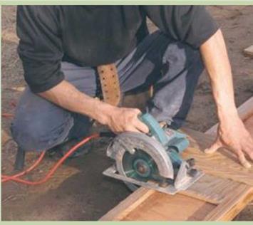
I-JOIST CUTTING GUIDEI-joists are awkward to cut because the top and bottom chords are wider than the web. To overcome this difficulty, make a simple jig with 3/4-in.-thick plywood. Cut a rectangular piece of plywood to fit between the chords and serve as the base of the jig. Screw a longer piece to the first piece, positioning it to guide a 90-degree cut. The edge of the top piece guides the base of the circular saw, as shown in the photo at right. Lay the guide on the I-joist, set the saw on it, and make a square cut. It’s that simple.

Cut I-joists with a guide. Scrap sheathing that is nailed or screwed together creates an effective guide for cutting I-joists. [Photo by Roe A. Osborn, courtesy Fine Homebuilding magazine © The Taunton Press, Inc.]

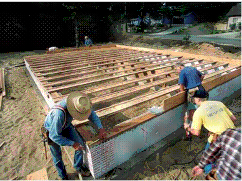
Подпись: Install the rim joists. The outside face of the rim joist (also called a band joist) must be flush with the outside edge of the sill. Toenail each joist to the sill, spacing 16d nails 16 in. o.c.

swell, shrink, crack, or warp the way solid lumber does. They are much lighter and easier to carry than 2x joists. And they’re uniform in size. In a load of 2x joists, you might find up to 3/8 in. of variation in joist width. I-joists don’t vary; once installed, they create a dead – level floor. Nails driven through the sheathing into the top chord are less likely to come loose and create a squeaky floor, especially when the sheathing is applied with adhesive. In terms of price, they are competitive with standard-

dimension lumber. Installation details for I-joists are slightly different than those for 2x joists. I’ll cover those differences just ahead.

Nail rim joists first

Rim joists form the exterior of the building and are the first joists to be installed. The layout of other joist locations are marked on the top edges of the rim joists. Cut the rim joists to length and toenail each one flush with the outside of the sill. I drive one 16d nail every 16 in. around the perimeter (see the photo at left). Don’t forget that nails going into PT wood should be hot-dipped galvanized. In earthquake and high-wind areas, code may require that the rim also be secured to the sill with framing anchors, so check with your local building inspector. If there are no vents in the foundation, they can be cut into the rim joists. A standard screened vent fits in a 4//2-in. by 14//2-in. opening.

If you’re framing a floor with I-joists, you’ll probably use the specially made OSB rim joists supplied with your I-joist order. Install rim joists along only one side of the house. Then lay the I-joists flat across the sills, butting the end of each joist fast against the installed rim joist. The opposite ends of the joists will extend over the sill at the other side of the house. You can now

snap a line across the ends to establish where the I-joists need to be cut. A simple jig, explained in the sidebar on the facing page, makes it easy to cut the joists smoothly and accurately. After cutting the I-joists to length, complete the rim joist installation.

Joist layout goes quickly

When a single joist spans a house from edge to edge, the layout is identical on parallel rims. Just hook a long tape on the end of the rim joist and make a mark on top every 16 in. (32 in., 48 in., etc.) down the entire length. Put an “X” next to each mark to indicate which side of the line the joist goes on.

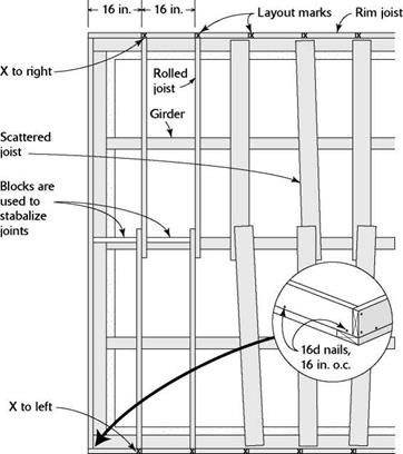
When the joists lap over a central girder or wall, the layout on the opposing rim joists must be staggered. On one rim joist, mark the 16-in. o. c. locations with an “X” to the right; on the opposite side, lay out the joists with an “X” to the left. This allows the joists to lap and nail over a girder or crib wall, where they will be stabilized with blocks (see the illustration on p. 68).
Подпись:

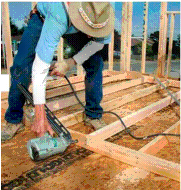
I-JOIST CUTTING GUIDE Подпись: With a little training, almost everyone can learn to safely use a nail gun to frame walls, though a trained professional or an experienced volunteer under supervision should use them. [Photo by Don Charles Blom]

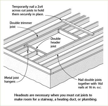
I-JOIST CUTTING GUIDEYour joist layout may include openings (called headouts) for a stairway or to provide clearance for plumbing or vents. Your plans should show these openings, but it’s always a good idea (and it could save a lot of time and effort) to check with the plumber. A common mistake is leaving insufficient room between

Подпись: IIII III III III III III III III III II III III III III III III III III II III III III III III III III III II III III III III III III III II III III III III III III III III II III III III III III III III III II III III II JOIST LAYOUT I-JOIST CUTTING GUIDERoll and nail the joists

Once the joists are cut to length and in position, carpenters say that it’s time to “roll” them. This just means setting the joists on edge, aligning them with their layout, and nailing them in place. If you are working with 2x joists, it’s im­portant to sight down each joist to see whether there’s a bow or a crown, and then set the joist with the crown facing up.

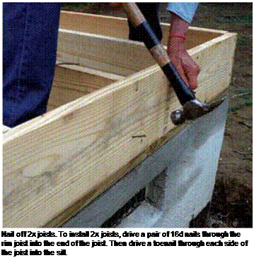
Drive two 16d nails through the rim joist directly into the end of the joist—one nail near the top and one near the bottom (see the photo below). Most codes also require that joists be toenailed (one 16d on each side) to the sill plates and supporting girders. To nail off an I-joist, drive a 16d nail through the rim joist and into each chord, then nail the chord to the sill on both sides of the web.

Make sure that all the joists are nailed securely. This is important for safety reasons, for quality workmanship, and for meeting code requirements. Once all the joists are nailed upright, stop and check for symmetry—make sure the line of one joist is parallel with another.

I-JOIST CUTTING GUIDE

Подпись: If a single joist spans from rim to rim, the layout is identical on each rim. When joists lap midspan, the layout on opposing rim joists must be staggered.
Подпись: Blocking adds strength. Install blocking between joists directly over the midspan support. Nail the blocking to the joists and to the top of the girder or crib wall.the joists for the tub’s trap and the toilet’s drain. You may need to frame a headout to make room for plumbing. For headout framing details, see the sidebar on p. 67. When framing with I-joists, remember that, like any other type of engineered joist, they cannot be notched or cut midspan with­out destroying their structural integrity.
Cut the joists in place

Подпись:If you trust your eye, try cutting 2x joists in place rather than measuring each one indi­vidually. As you become comfortable using a circular saw, you’ll be able make a square cut without using a square (see the sidebar on the facing page). This technique is definitely worth learning. Over the course of framing a house, it will save a significant amount of time.

Good Ventilation: Different Paths to the Same Place

When ventilation removes contaminants, it’s your friend, but in doing so, it usually brings in outdoor air that must be heated, cooled, or dehumidified, which costs money. Just because it costs money, though, doesn’t mean ventilation is your foe. The energy savings of a tight house more than offset the operating cost of a small fan, not to mention the costs of asthma and allergy medications. The trick is to design a ventilation system that provides acceptable indoor air as efficiently as possible. The system’s design depends on where you live, but the ASHRAE ventilation standard can guide you through alternatives. Every ventilation system likely will be a little different. In general, though, there are three approaches to whole-house ventilation—exhaust, supply, and balanced systems—each a little more involved and more expensive than the last.

Exhaust Ventilation Clears Pollutants at Their Source

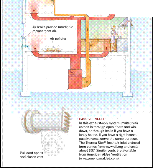
The simplest system, exhaust only, provides mechanical ventilation with a continuously operating exhaust fan (see the drawing on the facing page). This fan can be as simple as upgrading your bath fan or as complex as installing a multi-room exhaust fan. The exhausted air is replaced by air infiltrating through leaks (in humid climates, this can cause moisture problems). But rather than doing so at the whim of the weather, it is being done at a steady level with the fan. With the quiet, energy-efficient fans avail­able today, this option is cheap and easy. Be­cause its makeup-air requirements are small, a low-volume exhaust fan won’t depressurize your house enough to cause backdrafting. This system also has the advantage that it can be used in homes without ductwork.

The simplest way to make sure contaminants don’t build up in a house is to suck them out with one or more continuously running exhaust fans. This ap­proach is the least expensive, is the least invasive, and has the advantage of working in houses without existing ductwork. For whole-house ventilation, ex­isting kitchen and bath fans must be left running, a noisy prospect unless you have super-quiet models. A better solution is to use a multiport fan (see the drawing on p. 36) in the attic to exhaust many rooms simultaneously.

Exhaust fan


Ґ.


Good Ventilation: Different Paths to the Same Place

t

1 I • jr*

II ‘1

————- J

Щ

П

‘–

t

ШІ


Laundry

room


Good Ventilation: Different Paths to the Same PlaceGood Ventilation: Different Paths to the Same Place

Good Ventilation: Different Paths to the Same Place

Three Design Choices for Hot, Humid Climates

I

n a hot, humid climate, drawing fresh air into a house can be a problem. You can inad­vertently introduce 8 gal. of water a day from ventilation air. When combined with internally generated moisture sources, this is way too much. There are three design options to con­sider or combine.

1. Tolerate

You can accept periods of high moisture levels if you use moisture-tolerant materials. Hard, cleanable surfaces are better choices than fuzzy ones. Use hardwood floors instead of car­pet, or tile, plaster, or brick rather than paper­faced drywall.

2. Desiccate

Get the extra moisture out of the air by con­densing it and draining it. Air conditioners can remove moisture, but they usually are sized and designed for controlling temperature.

In some climates, they won’t dehumid – ify enough under normal use. A better option is a standalone dehumidifier or enhanced dehumidification gear.

3. Procrastinate

Some humid climates have dry seasons. It might be possible to use reservoir-type buffer materials that store moisture during hot, humid pe­riods, then release it during dry ones. Examples of such materials are brick interior walls, cellulose insulation, and solid-wood exposed beams.

A downside is that this system blows out heated (or cooled) air and, therefore, wastes energy. Another downside is that you don’t know where the ventilation air being sucked in is coming from (or where it has been).

Air from a garage or other polluted space shouldn’t be inadvertently brought into a house. Passive-intake vents are a simple way to offset this problem (see the photo on p. 33).

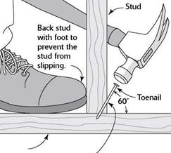
TOENAILING BASICS

TOENAILING BASICSПодпись: Bottom plate Start the nail at a 60° angle, about 1 in. from the end of the board. Подпись: When it's not possible to drive a nail directly through one piece of wood and into another, join them with a toenail.Driving a couple of nails through the side of one 2x into the edge or face of another creates a strong connection. This is a good way to join two 2xs at a right angle. But sometimes this isn’t possible, either because the board is too thick or because its face is not exposed. That’s when you resort to driving a nail at an angle, or toenailing.

To toenail two boards together, hold the nail at a 60-degree angle and start it about 1 in. from the end of the board. If the nail angle is not correct, the connection between the two pieces of wood will not be as strong. Back up the wood with your foot to hold the board in place as you toenail. With practice, you’ll soon gain skill, speed, and confidence.

Подпись: The girders that support the joists need to break over a post. [Photo by Don Charles Blom]

attaches to the pier post and holds it in position. Secure a TT-in.-thick pressure-treated pad to the top of the pier if the posts will be cut from untreated lumber. You can measure for the post’s length just as you measured for the crib wall’s studs, stretching a line above a piece of girder stock placed on the pier. Cut your posts to length, then secure them directly to the piers or toenail them to the blocks attached to the piers. Make sure the posts are plumb and paral­lel to one another.

Girders must butt together over a post. When the end of a girder fits into a pocket in the foun­dation, you’ll have to shim up the girder to get the top surface level with the top of the sill. The shims used beneath girders will bear the full weight of the floor, so they must be cut carefully from pressure-treated stock. Cut uniformly thick shims instead of tapered ones and make them large enough to fit in the bottom of the founda­tion pocket. Rather than foundation pockets, we inserted a metal 4x post base in the footing next to the stem wall to hold the end of the girder.

Подпись: Plywood gussets tie girders securely to their post supports. [Photo by Don Charles Blom] Подпись: Patterns save time. When cutting multiple identical pieces of framing mem-bers, such as joists, it is common to use a pattern piece. Cut one piece to the correct length, then lay it on top of the next piece to be cut and mark that one. Write the word “pattern” on the original piece. Подпись: Because of concrete’s ability to absorb mois-ture, code requires that the end of the girder be held about Vi in. away from the back of the pocket when cutting the girder to fit. If you’re not using pressure-treated stock for the girder, you can wrap the end of the girder with builder’s felt or sheet metal to give it some protection against moisture damage. Toenail the girders to the posts with either four 8d or three 16d nails. Now brace the posts and splice the girders by nailing the plywood gussets on both sides of the joint (see the illustration on p. 48). STEP 6 INSTALL THE JOISTS Подпись: Joists span a house from edge to edge, providing support (and a nailing surface) for the subfloor and a platform for the walls. Many older houses were built with undersized joists that were unable to keep floors and ceilings from sagging. Building codes today help ensure that joist sizing and spacing are more than adequate to keep floors rock solid yet resilient. Joists are normally spaced to allow for the most efficient use of full-size (4-ft. by 8-ft.) sheets of OSB or plywood. Joists cut from 2x lumber are generally spaced 16 in. or 24 in. o.c. Engineered wood I-joists can be spaced on centers of 12 in., 16 in., 19.2 in., or 24 in.Solid lumber versus engineered I-joists

Up until 20 years ago, most of the floors in this country were built with standard 2x joists. These days, more floors are being built with engineered I-joists. So named because of their “I” profile, I-joists have plywood top and bottom chords connected by an OSB web (see the top left photo on p. 62). They offer several advan­tages over solid lumber. Being an engineered product, they are knot-free and can span long distances without interior support. I-joists don’t

PNEUMATIC NAILERS

Volunteers who help build Habitat houses use only hammers to drive nails. But these days, buildings are nailed together with all kinds of pneumatic nailers. These are good, reliable tools, available for framing, finish work, siding, and shingling. However, there are basic safety considerations to keep in mind.

■ Treat a pneumatic nailer with respect. Be mindful of what you are doing. Never point a nailer at yourself or at others.

■ Read and follow the instruction manual regarding its maintenance and use.

■ Don’t walk around with your finger on the trigger. You could acci­dentally fire a nail.

■ Adjust the air pressure as needed. Larger nails require more pressure.

■ Wear safety glasses or goggles.

■ Disconnect the nailer from the air compressor before clearing a jammed nail.

■ When nailing on a sidewall, don’t hold the nailer in front of your face. Hitting a metal strap or other hardware beneath the surface could cause the nailer to recoil into your face with considerable force.

■ Drain moisture from the compressor tank after using it. A rusty, compromised tank can explode under pressure.

■ No one under 18 years of age should use a pneumatic nailer.

■ Pneumatic nailers should only be used by a trained professional or an experienced volunteer under supervision.

EXAMPLES FROM THE DEMONSTRATION PROJECTS

Подпись: Phoenix, Arizona Open-space in Cimarron PUD Подпись: Tulsa, Oklahoma A majority of the projects in the Joint Venture for Affordable Housing (JVAH) were developed under some version of Planned Unit Development zoning or subdivision regulations.

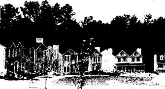
Knoell Homes, developer of Cimarron, the’JVAH Project in Phoenix, saved at least six months by utilizing the PUD approach instead of applying for rezoning under the standard sub – _ division ordinances. This time saving reduced interest cost by approximately $106,000 or about $415 per unit. The cost reduction was passed on to the home buyers.

Rick Counts, former Phoenix Planning Director, expressed his frustration that PUDs require Home Owners Associations (HOAs). Many builders do not want to involve themselves with HOAs, and avoid using PUDs for that reason.

Hood Enterprises, developer of Innovare Park, applied for and was granted residential multi-family zoning for the site. The developer then applied for and was granted a supplemental PUD zoning permit. Under this permit, Hood Enterprises negotiated a site plan with city officials that allowed all single­family construction. The density – 12 units per acre – exceeded allowable maximums under standard single-family zoning for the area, but reduced the density that would have been allowed in multi-family develop­ment. The arrangement satisfied city officials, who stated that the PUD

Подпись: Lacey, Washington Подпись:EXAMPLES FROM THE DEMONSTRATION PROJECTSapproach "provides a higher degree of regulation but permits the developer more flexibility in principal and accessory uses and of lot sizes than conventional zoning."

In developing "The Park", an afford­able housing demonstration in Lacey, Phillips Homes used a PRD authoriza­tion that allowed the developer to ‘ construct a mix of townhouses and detached units, and to make his own decisions regarding lot sizes. Phillips added 23 building lots to the 153 that were originally planned, bringing the total to 176.

The city of Birmingham rezoned Williamsburg Square, a project built by Malchus Construction Company, as a PRD, enabling Malchus to increase density from 40 to 111 units. The PRD designation also accelerated processing time from the normal 6 to 18 months to five months, saving $9,600 on the subdivision or $86 per unit, with the saving being passed on to the buyers.

Lincoln, Nebraska The City of Lincoln allowed Empire

Homes, Inc., to include its affordable housing project, "The Parkside Village," in an already-approved Community Unit Plan (CUP). This made it possible for the developer to increas’d the project’s density from 32 to 52 units.

EXAMPLES FROM THE DEMONSTRATION PROJECTS

Подпись: Portland, OregonBlack Bull Enterprises, Inc., developer of the affordable housing project "North Meadow Village," sought and secured from the city a number of innovative zoning modifications for the land parcel of which North Meadow Village forms one part. The parcel is situated in an area zoned for low-density, single-family construction at four units per acre. Black Bull requested establishment of a multi­family zone (22 units per acre) around a shopping center in the 150-acre tract located on a two-lane state highway, and a medium-density single­family strip (6.28 units per acre) separating the low-density single­family zone from the multi-family zone. In effect, he asked the Planning Bureau to trade higher densities in one portion of the tract for lower water and sewer usage in the commercial and retail area, with no net change in total water and sewer demand. The rezoning was approved by the city.

The city added PUD provision to its zoning regulations in 1980. Under this provision, Minchew Homes, developers and builders of "Forestwood II," were able to increase density from 2.9 to 5.8 units per acre.

Подпись: Valdosta, GeorgiaПодпись: Oklahoma City, OklahomaUnder this city’s PUD, Holland Land Company was able to cluster homes, increase open spaces, and mix single­family detached units, duplexes,, and quadplexes in "Woodland Hills," a subdivision of HUD-code manufactured homes.
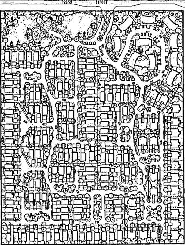
Ull


I


Woodland Hills


EXAMPLES FROM THE DEMONSTRATION PROJECTS

Other JVAH demonstration projects developed and built under PUD-type ordinances include: Elkhart, Indiana; Knox County, Tennessee; and Charlotte, North Carolina.

Подпись:
Housing developments are built on borrowed money on which the developer makes interest payments each month. Developers also incur an overhead cost each month. The more quickly the homes can be built and sold, the more the interest and overhead costs can be reduced. According to a study by the Los Angeles County Land Development Center, every month of delay adds, by conservative estimate, 2 percent to the purchase price of a new home. These savings can be passed on to home buyers. Local jurisdictions can therefore make a direct contribution to affordable housing by expediting theirprocedures regulating land use and housing construction.

“Most builders don’t know the true cost of delay. Everyone assumes that it’s only interest, but the true cost includes overhead, material and labor inflation, and the lost opportunity to make a profit.”—John Phillips

Housing is governed at the local level by an array of codes, rules, and procedures which have typically grown up over a substantial period of time, and which often do not repre­sent a coordinated system. A basic step that municipalities can take to promote affordable housing is to review the entire regulatory process from zoning through permitting as it is actually experienced by developers, to identify procedures that can be simplified, abbreviated, or improved.

“Concurrently with the Affordable Housing Demonstration project,” commented Jon Wendt, “Phoenix was pursuing an aggressive regulatory relief campaign under the leadership of Mayor Hance. Cimarron provided tangible evidence of the benefits to citizens of government deregulation. From the start, our primary interest in the project was to field tesj deregulation ideas to see if they worked, and, if they did, to incorporate them as permanent changes.”

Municipalities may wish to implement certain changes immediately. In other instances, changes that appear to be desirable can be used to expedite a specific affordable housing project as a test. The project can be evaluated, the changes modified if necessary, and support gained among agencies and officials who will have to implement them.

Task Force


A working group of public officials, builders and developers, representa­tives of community groups, and consultants should conduct such a review and make recommendations. This can achieve three goals.

1. ‘■ It gives the task the status of a

community effort in which diverse interests and views are represented.

2. It helps to consolidate community support for the recommendations •and the action that is taken to implement them.

3. It helps to broaden awareness and understanding of affordable housing and of the municipality’s support of it.


The

Mayor’s Task Force on

Affordable

Housing


October 1983 Santa Fe New fVlexico


Review Areas


EXAMPLES FROM THE DEMONSTRATION PROJECTS

Areas recommended by the National

League of Cities for review include

the following:

• Length of the process from application to approval or issuance of a permit. A builder/developer should know how much time it will take before a decision is made on his or her proposal. For example, there should be a fixed review period for subdivision plans, at the end of which, if no action has been taken, the plan will be automat­ically approved.

• Number of permits, approvals, hearings, and administrative reviews necessary for construction, and the additional number necessary for occupancy.

• Number of agencies, departments, boards, and other groups that must review an application.

о Types of information and amount of detail necessary for the kinds of approvals that are required.

Techniques that can be used in such a review study include:

Подпись: Review Techniques Review of city records to ascertain the number of applications received and approved, the agency or agencies involved, and the length of time involved.

• Review of items in process during a specified current period, to learn how the system works in practice and where problems may exist.

Подпись: Application Process ReviewThe study should examine each of the three principal stages of the applica­tion process and make recommenda­tions for improving procedures at each stage, as follows:

1. The Pre-application Stage

In this stage, the developer should receive an overview of all that will be required during the regulatory process, including approvals needed, departments involved, and the best methods for moving through the system efficiently, and should be advised of the anticipated timeframe for approval.

2. The Staff Review Stage

Procedures can be reviewed for fast-tracking possibilities, ways to offer combiried or simultaneous reviews, mandatory deadlines, involvement of expediters or coordinators, elimination of duplication of review among Various agencies, concurrent reviews, and use of a management information system to track applications. Some local govern­ments have developed a plan* review checklist to guide devel­opers through the review proce­dures. If all steps on the

checklist are carefully followed, the review can be brief and relatively simple.

3. The Citizen Review Stage

Not all communities have ordi­nances that provide for citizen review procedures. Where such reviews are required, they target possible improvement in such areas as: convening of informal neighborhood meetings to dissemi­nate information and respond to concerns prior to finalization of designs or the holding of public hearings; improvement of public hearing procedures through adoption of fair and consistent rules on who is heard, when, for how long, and how decisions are made; combining hearings when the approval of more than one governmental body is required; shifting some responsibilities from the planning commission to a hearing official, staff, or other party or entity; and adoption of mediation procedures in lieu of resorting to the courts to resolve difficult cases.

Подпись: Inspections and PermitsCity staff responsible for inspection must respond to builder and developer requests in a timely and scheduled manner. Developers and builders have a responsibility to assure that the work for which inspection is requested has been completed and meets the relevant criteria. Cities are justified in requiring that their time and expertise are efficiently used.
Permit and inspection fees should bear a reasonable relationship to the actual cost of performing the inspec­tions and issuing the permits. It is inappropriate to use them as a form of indirect tax.

•*-y

STEP 5 BUILD MIDSPAN SUPPORT FOR JOISTS

Unless you are building on a slab, you’ll prob­ably need to provide midspan support for the floor joists. Without additional support some­where between the sills, the joists can be over­spanned, resulting in a finished floor that sags or feels bouncy. A friend once took me through

STEP 5 BUILD MIDSPAN SUPPORT FOR JOISTS

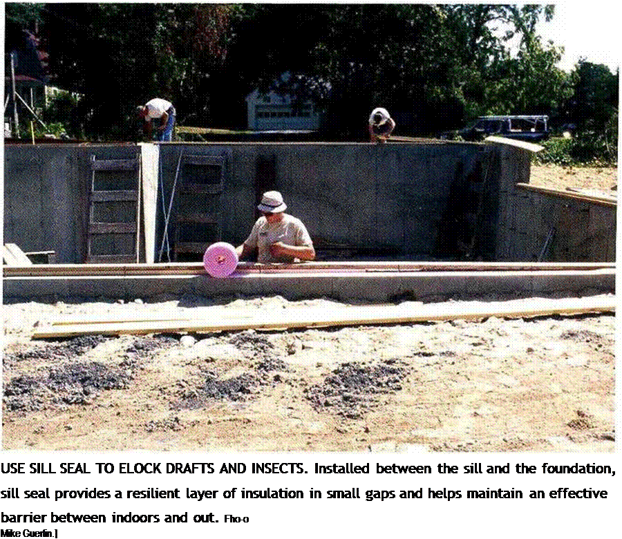
Use sill seal to block drafts and insects. Installed between the sill and the foundation, sill seal provides a resilient layer of insulation, filling in small gaps and helping maintain an effective barrier between indoors and out.

[Photo © Mike Guertin]


his 18th-century home in rural Connecticut. The beautiful, hand-hewn floor joists in the basement were fascinating—dry, free from rot and termites—but far overspanned. Upstairs, it felt like walking on ocean waves. Clearly, what was needed was some support to keep the joists from sagging and bouncing in the middle.

Codes require a minimum of 18 in. between the earth and the joists in a crawl space. These days, two systems are commonly used to provide midspan support for the joists: crib walls (also called pony walls) and post-and-girder systems. A crib wall is just a shortened version of a regu­lar stud wall and is supported along a continu­ous concrete footing. With a post-and-girder system, a solid or built-up girder (also called a beam) is supported by posts every 6 ft. or so, depending on code. The girder usually fits into a recess or pocket where it meets the foundation wall. Joined to the girder by metal connectors or plywood gussets, the posts bear on concrete piers (see the illustration on p. 48).

In both these systems, the joists rest on and are nailed to the top support member.

Подпись:The width of the joists and the length of the span determine how much support is needed. With 2×6 joists, for example, posts and girders are often placed every 6 ft. With 2 x12s or
STEP 5 BUILD MIDSPAN SUPPORT FOR JOISTS

STEP 5 BUILD MIDSPAN SUPPORT FOR JOISTS STEP 5 BUILD MIDSPAN SUPPORT FOR JOISTS
STEP 5 BUILD MIDSPAN SUPPORT FOR JOISTS

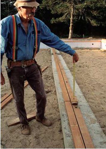
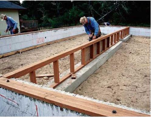
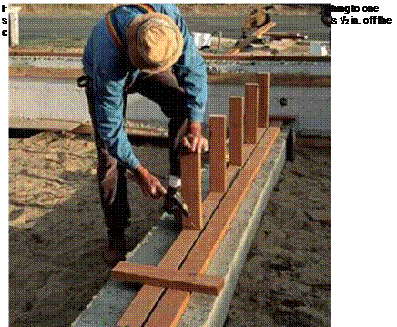
Build a crib wall. It’s best to use PT wood in underfloor areas. Crib walls (also referred to as pony walls) are short, stud-framed walls and can provide midspan support for joists that extend over a crawl space. After bolting the wall’s bottom plate to the footing, stretch a line over the sills to measure the length of the crib wall’s studs (see the photo above). Place two pieces of top plate stock on the wall’s bottom plate and measure up to the line. Toenail the studs to the bottom plate, spacing them 16 in. o. c. or 24 in. o. c. depending on your code requirements (see the photo below). [Photos © Memo Jasso]

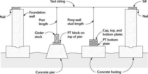
Подпись: Ill III III III III III III III III III III II III III III III III III III III III III III III III III II III III III III III III III III III III III III III II III III III III III III III III III III III III III III II III III III III III III III III III III III III III II III MEASURING POST OR PONY-WALL STUD LENGTHS STEP 5 BUILD MIDSPAN SUPPORT FOR JOISTSWait to carpet over concrete. Make sure you let a con­crete slab dry out well (for several months) before laying carpet on it. If you don’t, the carpet adhesive may not hold properly and your carpet could rot, possibly posing a health hazard.

STEP 5 BUILD MIDSPAN SUPPORT FOR JOISTS

Stretch a string tightly from one sill to another. For the post length, measure from a piece of girder stock to the taut string. To find the stud lengths for a pony wall, measure from the top of a stack of three wall plates to the string.

engineered I-joists, only one support in the center may be needed.

Crib-wall construction

Just in case a moisture or termite problem develops in the future, I like to build crib walls with pressure-treated wood. To determine the length of the crib wall’s studs, first bolt the wall’s bottom plate to the footing. Then tightly stretch a string above the crib wall’s bottom plate and across the mudsills installed on the stem walls. Set two pieces of top plate stock on the bottom plate. The distance between the top plate stock and the string is the length of the crib wall’s studs (see the top right photo on the facing page).

Toenail the studs to the bottom plate, spac­ing them 24 in. o. c. but leaving a 30-in.-wide opening somewhere in the wall so that plumbers, electricians, and others can get from one side of the crawl space to the other. When toenailing the studs to the crib wall’s bottom plate, you can drive either four 8d toenails or three 16d nails per stud. If you’re using a pneumatic nailer,
make sure you follow the safety guidelines explained in the sidebar on p. 65.

Once the crib wall’s studs are in place, nail on the two top plates. Drive a pair of 16d nails through the first plate into the top of each stud. Secure the double top plate with a single 16d nail at each stud location, and toenail the plate’s ends to the sill on the foundation wall at each end of the house. I like to sheathe sections of a crib wall with pressure-treated plywood (my first choice) or OSB to provide good lateral bracing (see the bottom left photo on the facing page). Be sure not to sheathe over the crawl-through opening you framed in the wall. As an alternative to sheathing a crib wall, you can stiffen it with 2x diagonal braces nailed to the top and bottom plates and across at least one stud.

Build a post-and-girder system

Posts used to construct a post-and-girder system can be anchored directly to a metal post base that is set in the concrete footing. You can also use a precast pier with a metal strap that

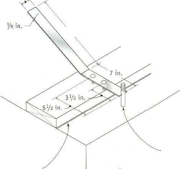
MAKING A BOLT-HOLE MARKER

Подпись: 1У2 in.Подпись: Anchor bolt Подпись: 11 in.Подпись: CnalklineMAKING A BOLT-HOLE MARKERSelect an 18-in. by іУг-іп. by Vs-in. metal plate strap.

Cut a notch in one end of the strap so that it will fit around a Уг-іп. or 5/s-in. bolt. From the center of the notch, measure back 3!/г in. for a 2×4 plate and 5V2 in. for a 2×6 plate. Drill holes at those points and insert 3/i6-in. by 3/Vin. stove bolts. Put a bend in the plate strap to make it easier to use.

Подпись: Slab or foundationA bolt-hole marker makes it easy to transfer the bolt location to the sill in preparation for drilling a hole.

MAKING A BOLT-HOLE MARKERПодпись: AN ELECTRIC DRILL IS GREAT FOR BORING HOLES. Use a spade bit in an electric drill to bore bolt holes through a wood sill.

Install sill seal and termite shields

Sweep the foundation clean of debris, then put down a layer of sill seal insulation where the sills will he located (see the photo on the facing page). Sill seal does just what its name says. As an alternative, you can run two heavy beads of silicone caulk between the sill plates and the foundation. This also prevents cold air leaks between the foundation and the sill. In areas where termite infestation is a possibility, you’ll also need to lay down a termite shield over the foundation bolts and under the sill. As shown in the illustrations on p. 46, the shield edges must extend beyond the founda­tion (including the foundation insulation) and the sill.

Подпись:Place the sills over the bolts, put on the washers and nuts, and tighten the nuts with a crescent wrench, taking care to keep the inside edge of the sill on its layout. Note: When working on a slab, drill holes n the plates but leave them unbolted until after the wall is raised (see chapter 4 for details).

If the measuring work you did at the beginning of this step told you that parts of the foundation were out of level, you can expect the sills to be that way, too. To correct slight discrepancies (up to A in. or so), you can insert pressure-treated shims underneath the sills. For larger errors, it s best to call in a concrete contractor.

Urban Residential Drives

Either type 1 or type 2 drives (Fig. 2.49) may be used in urban areas. If used in urban areas, the radius and flare dimensions may be reduced so that the apron does not extend past the back of the sidewalk, or past the right-of-way line if there are no sidewalks. The desirable minimum radius for type 1 drives, when the through highway is curbed, is 15 ft (4.6 m).

Three methods are shown in Fig. 2.50 for designing driveways between the curb line and sidewalk to provide for turning vehicles. Other designs may be used if they are approved for use by the local governmental agencies responsible for maintenance of the project. Additional details are shown in Fig. 2.51 when the tree lawn is less than 6 ft (1.8 m). Residential drives on curbed streets should use a dropped curb as shown in section B-B of Fig. 2.50.

Rural Driveway Geometries

Rural residential drives and field drives should normally conform to the type 1 design shown in Fig. 2.49 (Ref. 14). New drives should intersect the highway at an angle between 70 and 90°. In some cases, however, it may be necessary to retain existing drive angles that vary from these desirable angles.

If the project involves existing drives, the existing width is normally retained unless it is less than 12 ft (3.7 m). In that case, it should be widened to provide a 12-ft (3.7-m) throat width. In the case of new drives, the width should normally be 12 ft (3.7 m). If the new driveway is a combined drive between two properties, the width should nor­mally not exceed 24 ft (7.3 m). Also, a wider field drive may be used if it will keep a farm equipment operator from encroaching on the opposing traffic lane when entering or exiting the highway.

The radius of the type 1 driveway should normally be 25 ft (7.6 m). The radius may be increased on field drives if it is deemed that the larger values will improve dri­veway operation and reduce the hazard to motorists and farm equipment operators.

Driveways abutting uncurbed highways may be curbed. However, the curb should not extend closer to the through pavement edge than 8 ft (2.4 m) or the treated shoulder width, whichever is greater. This is recommended to avoid curb obstruction for vehicles, snowplows, etc., using the shoulder.

DRIVEWAY DESIGN

1.10.1 Location

Part of the process in obtaining a driveway permit is to determine where the driveway will be located. The following guidelines may be used to establish this location.

Wherever possible, drives should be located in accordance with the intersection sight distance criteria (see Table 2.3). Special consideration should be given to the location of drive access to high-volume traffic generators such as shopping centers and industrial plants and parks, as well as other types of development having similar traffic characteristics. These should be treated as standard intersections with appropriate spacing to the nearest intersection. A driveway serving all directions of traffic should be located a minimum of 600 ft (183 m) from the nearest major highway or street inter­section. A new driveway should not be located where it will create an offset intersection opposite an existing street, highway, or major commercial driveway.

Water Content

A fundamental parameter that characterises the water movement in pavements is the water content. This provides information on the condition of the road layers regarding the moisture saturation stage, which controls the main parameters in the governing equations for water flow (see Chapter 2, Section 2.8). A number of meth­ods are available for measuring water content. They can be divided into destructive methods (gravimetric methods) and non-destructive methods that provide indirect measurements of the water content.

3.2.1 Gravimetric Method

Water Content Подпись: (3.1)

The simplest and most widely used method to measure the soil water content is the gravimetric method where a soil sample is taken and weighed, dried in an oven at 105 °C for 24 h and then reweighed. To shorten the drying period a microwave oven can be used as an alternative, although this method introduces the possibility of removing chemically bonded water which would lead to an over-estimation of water content. The gravimetric water content, w, is the mass of water per mass of dry soil (see Eq. 2.10) or

where Wb is the total (or “bulk”) weight of the soil and Wd is the dry weight of the soil.

This method has two major drawbacks: the sampling is destructive for the road and the method can not be used to make in-situ measurements in real time. However it is an accurate method and is often used to calibrate other measurement techniques.