On the steppes of central Asia: Irrigation in Bactria and Margiana before the arrival of Alexander the Great

Bactria, to the east of the Zagros mountains and the Iranian plateau, is connected to the Syro-Mesopotamian world through a continuous thread of ancient exchanges, and thus it also must be mentioned in this chapter. Bactria was a land of plenty and fertile val­leys as noted by Strabo:

“Man has only to take the trouble to irrigate, and all crops grown abundantly with the excep – 53

tion of the olive tree”.

In Chapter 1 we mentioned the appearance of the Bactria-Margiana civilization, or the Oxus civilization, for which the mastery of irrigation is a fundamental pillar. It is doubtful that Bactria ever really fell under the Assyrian yoke, as is suggested in certain ancient sources. To the contrary, it was clearly part of the Achaemenid Persian Empire, and therefore belongs on the list of conquests of Alexander – but not without combat. Indeed, it was at Bactria that Alexander married Roxanne.

Successive hydraulic developments in the region became more and more general­ized from the IVth millennium BC. In Margiana and western Bactria, rivers that used to disappear into the desert before reaching the Oxus River form deltas that are developed and irrigated in the IInd millennium BC. Among the oases on the deltas are those of Geoksiur (mentioned in Chapter 1), Merv (Marw) on the Murgab River (to be discussed further in Chapter 7), Sherabad, Ulambulak and Mirshada on the right bank of the Oxus in western Bactria, and Bactra (Balkh) to the south, capital of the region toward the end of the IInd millennium BC. Russian archaeological studies have shown that at Merv, [84]

On the steppes of central Asia: Irrigation in Bactria and Margiana before the arrival of Alexander the Great

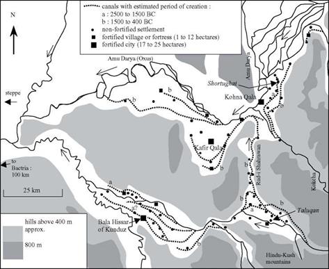
Figure 2.20 Irrigation canals in eastern Bactria on the eve of the arrival of Alexander the Great, near the confluence of the Oxus and the Kokcha (Gentelle, 1989; Gardiun, 1998). The irrigated fields are located between the canals and the rivers. The sites shown in italics (Shortughai and Taluqan) date from the IIIrd millennium BC.

habitation progressively migrates upstream as aggressive irrigation starves the down­stream extremities of the network.54 In Sogdiana to the north, one can also find rem­nants of early irrigation at Sarazm, on the Zeravchan River (the watercourse on which Samarcand is later founded). One also finds such traces on the lower course of the Oxus, to the southeast of the Aral sea, and at Dehistan, to the southeast of the Caspian (see Figures 1.3 and 7.1 for location maps).

Irrigated agriculture develops naturally in the valleys of the Oxus and its tributaries in western Bactria, at the foot of the great mountains of Hindu Kush and Pamir. French explorations conducted between 1971 and 1977 led to restitution of ancient canals, and helped establish a chronology of their evolution based on the dates of inhabited sites.[85] As agriculture spread to terraces situated higher and higher above the rivers, it was nec­essary to extend the canals so their intakes would be higher than the irrigated land, and to route the canals from one terrace to another. Often it was necessary to supply a canal from a tributary of the main river, sometimes far away, to bring water to the irrigated ter­races along the main river itself. For example, a plain that overlooks the Oxus at its con­fluence with the Kokcha was irrigated from the IIIrd millennium BC by a 25-km long canal fed by the Kokcha itself, and extending down to the Harappan settlement of Shortughai (Figures 2.20 and 7.2).

But even larger water resource developments appeared during the period from 1500 BC to the arrival of Alexander the Great – a period that also saw the development of major water supply in Assyria and Urartu. An artificial branch of the Taluqan River was excavated to develop the left-bank region of the Oxus, proceeding to the north against the natural drainage (Figure 2.20). This 50-km branch is today called the Rud I Sharawan. That the canal is artificial can be seen from its often perpendicular orienta­tion compared to the natural drainage. To the south, it follows the paths of old river arms or canals in the Taluqan plain; and to the north, it follows the valley of a small tributary to the Kokcha. The canal is deeply entrenched into unstable loess in its central portion that separates the drainage basins of the two rivers, attaining a depth of as much as 20 meters along one kilometer.

This is a significant operation of inter-basin water transfer, comparable to that implemented by Sennacherib to bring water to Khosr and Nineveh (Figure 2.15). Although it is impossible to say which of these developments came first, the necessary know-how clearly existed in both of these widely separated regions. What could have been the driving force for this project in Bactria: the decision of Persian leaders or the earlier work of a local Bactrian authority? Bactria had a strong cultural unity even before the arrival of the Persians. It may also have had strong political unity, but its his­tory is unknown.

Covariance and correlation coefficient

When a problem involves two dependent random variables, the degree of linear dependence between the two can be measured by the correlation coefficient pXyy, which is defined as

Corr(X, Y) = px, y = Cov(X, Y )laTay (2.47)

where Cov(X, Y) is the covariance between random variables X and Y, defined as

Cov(X, Y) = E[(X – ,ix)(Y – iiy)] = E(XY) – pPy (2.48)

Various types of correlation coefficients have been developed in statistics for measuring the degree of association between random variables. The one defined by Eq. (2.47) is called the Pearson product-moment correlation coefficient, or correlation coefficient for short in this and general use.

It can be shown easily that Cov(X^, X’2) = Corr(Xь X2), with X^ and X’2 being the standardized random variables. In probability and statistics, a random variable can be standardized as

X’ = (X – px)/ax (2.49)

Hence a standardized random variable has zero mean and unit variance. Stan­dardization will not affect the skewness coefficient and kurtosis of a random variable because they are dimensionless.

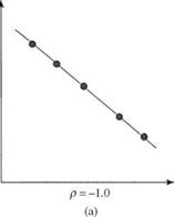
Figure 2.14 graphically illustrates several cases of the correlation coeffi­cient. If the two random variables X and Y are statistically independent, then Corr(X, Y) = Cov(X, Y) = 0 (Fig. 2.14c). However, the reverse statement is not necessarily true, as shown in Fig. 2.14d. If the random variables involved are not statistically independent, Eq. (2.70) for computing the variance of the sum of several random variables can be generalized as

/ k K K-1 K

Var ]T akXk = ]T aal + 2 £ ]T akak, Cov(Xk, X„) (2.50)

k = 1 ) k = 1 k = 1 k=k+1

Example 2.12 (after Tung and Yen, 2005) Perhaps the assumption of independence of Pm, Im, and Em in Example 2.11 may not be reasonable in reality. One examines the historical data closely and finds that correlations exist among the three hydrologic random variables. Analysis of data reveals that Corr(Pm, Im) = 0.8, Corr(Pm, Em) = -0.4, and Corr(Im, Em) = – 0.3. Recalculate the standard deviation associated with the end-of-month storage volume.

y


y


Подпись: XCovariance and correlation coefficient• •

_ • • • . •

• • •

p = 0.8

Подпись: X

(b)

У


У


x


x


p = 0.0

(c)


p = 0.0

(d)


Covariance and correlation coefficient

Covariance and correlation coefficient

Figure 2.14 Different cases of correlation between two random variables:

(a) perfectly linearly correlated in opposite directions; (b) strongly linearly correlated in a positive direction; (c) uncorrelated in linear fashion; (d) per­fectly correlated in nonlinear fashion but uncorrelated linearly.

Solution By Eq. (2.50), the variance of the reservoir storage volume at the end of the month can be calculated as

Var(Sm+1) = ar (Pm) + Var(Im) + Var(Em) + 2 Cov(Pm, Im)

— 2 Cov(Pm, Em) — 2 Cov(Im, Em)

= Var(Pm) + Var(Im) + Var(Em) + 2 Corr(Pm, Im)o(Pm)o(Im)

— 2Corr(Pm, Em)&(Pm)&(Em) — 2 Corr(Im, Em)&(Im)&(Em) = (500)2 + (2000)2 + (1000)2 + 2(0.8)(500)(2000)

— 2(—0.4)(500)(1000) — 2(—0.3)(2000)(1000)

= 8.45(1000 m3)2

The corresponding standard deviation of the end-of-month storage volume is a(Sm+1) = V845 x 1000 = 2910 m3

In this case, consideration of correlation increases the standard deviation by 27 percent compared with the uncorrelated case in Example 2.11.

Example 2.13 Referring to Example 2.7, compute correlation coefficient between X and Y.

Solution Referring to Eqs. (2.47) and (2.48), computation of the correlation coefficient requires the determination of xx, xy, ax, and ay from the marginal PDFs of X and Y:

4 -t – 3×2 4 -t – 3 y2

fx(x) = ——— for 0 < x < 2 fy(y) = ——— for 0 < y < 2

as well as E(XY) from their joint PDF obtained earlier:

Подпись: fx,y(x, y) = ■Подпись:3( x2 + y2)

32

Covariance and correlation coefficient

From the marginal PDFs, the first two moments of X and Y about the origin can be obtained easily as

Var(X) = E(X2) – (Mx)2 = 73/240 = Var(Y)

To calculate Cov(X, Y), one could first compute E(XY) from the joint PDF as

E(XY) = f ( xyfx, y(x, y) dxdy = |

J0 J0

Covariance and correlation coefficient

Then the covariance of X and Y, according to Eq. (2.48), is Cov(X, Y) = E (XY) – nxny = -1/16 The correlation between X and Y can be obtained as

Compression

Compression — in wood, not my father’s car engine — can be thought of as the tendency to crush or compress under a load. The actual crushing or compressing does not have to be measurable to be real. If 1 stand on a stout — say, 12-inch diameter by 12-inch high — oak chopping block, my weight puts that chopping block in compression, even though I am having no measurable impact upon it. My entire family could balance atop the block to no effect, yet the block is definitely in compression. It might seem that such a stout block would never fail under compression, and yet it can under extreme circumstances. In October of 2003, Jaki and 1 rotated a 20-foot long 20-ton stone on a 12-inch-wide pivot made of a dense hardwood, an incredible concentrated load. Yes, the pivot eventually failed — it was crushed and ruptured apart, finally — but we did manage to swing the stone through almost 90 degrees of arc before it did.

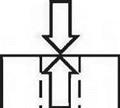
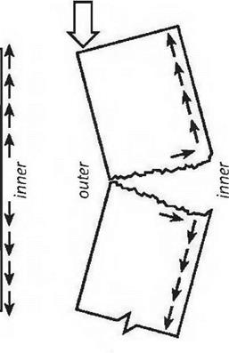
The stresses on posts or columns are due mostly to compression, particularly if the line of thrust from above is straight down through the center of the post, as in Figure 2.2a. (Our chopping block example, incidentally, is simply a short stout post.) However, if the line of thrust wanders out of the middle third of a post — or a wall — then the side of the post or wall where the load is concentrated is in compression, while the side away from it is in tension.

(Fig. 2.2b).


Fig. 2.2a: The line of thrust is in the middle third of the wall. The reactionary thrust is in compression.

Fig. 2.2b: The line of thrust has wandered into the outer third of the wall, still under compression, but the inner surface is on tension and the wall is unstable.

Fig. 2.2c: The line of thrust has left the confines of the wall, which now buckles and fails.


о


&

з

о


cu

c

c


Tension

Tension can be thought of as the opposite of compression. While comp­ression wants to squish the molecules of a material together, tension is trying


из


УЗ


1/3


1/3


1/3


1/3


Ar


Лг


2.2a


2.2b


2.2c


image7image8image9

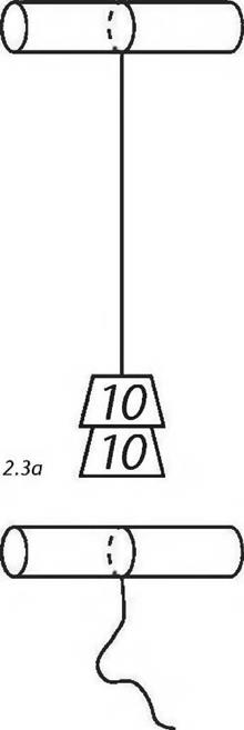
image10Подпись: 2.3bПодпись:image11to stretch the molecules apart. If I hang lead weights on a string, the string is in tension. If I keep adding more lead weights until the tensile strength of the string is exceeded, we will observe a failure in tension: the string breaks.

If the line of thrust actually leaves the edge of the support structure, as per Fig. 2.2C, the member will hinge somewhere along its height and something — like the upper story or the roof — will come crashing down.

While writing the above paragraph, I envisioned a building failing in the way described. It happens, particularly with old abandoned buildings under a severe load, such as heavy snow or strong wind. It occurred to me that the failed building lands up in some kind of an untidy heap, which, in and of itself, is actually a new structure, one designed instantly by the physics that apply near the surface of this planet. If you looked carefully at the resultant pile of twisted and broken timbers, you would see a structure with new lines of thrust being distributed along tension and compression, and by way of natural triangles and trusses. Such a pile might be weak, only able to support itself for a short time, or it might be surprisingly strong. An old barn building near us has been slowly receding into the landscape for 25 years.

We’ll talk more about posts later, but I think it would be helpful to consider beams first, because posts, surprisingly, share some of the same characteristics as beams.

FOUNDATION & STORM DRAINAGE

FOUNDATION &amp;amp; STORM DRAINAGE

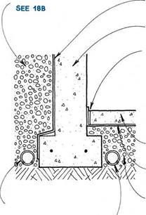
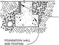
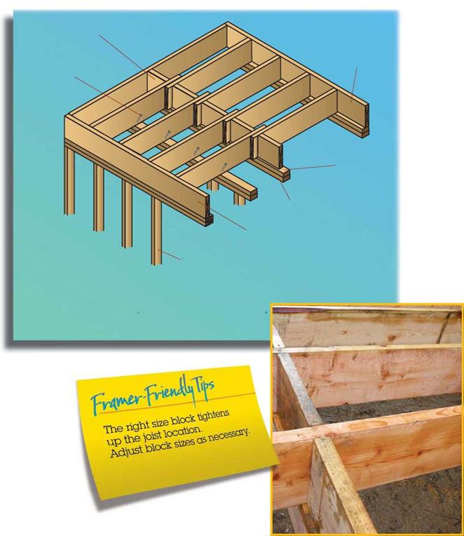
Drainage is essential in protecting a basement from groundwater, but waterproofing the basement wall from the outside is also vital. In selecting a water­proofing material, consider the method of application, the elasticity, and the cost. Below are common water­proofing and drainage materials.

Bituminous coatings—Tar or asphalt can be rolled, sprayed, troweled, or brushed on a dry surface. Often applied over a troweled-on coating of cement plaster that is called parging, some bituminous coatings may be fiberglass reinforced. They have minimal elasticity, and thin coats may not be impervious to standing water.

Modified portland-cement plaster—Plaster with water-repellent admixtures can look exactly like stucco. It is usually applied with a brush or a trowel to a moist­ened surface. It is inelastic, and unlike parging, it is waterproof.

Bentonite—A natural clay that swells when moistened to become impervious to water, bentonite is available as panels, in rolls, or in spray-on form. It is applied to a dry surface, and is extremely elastic.

Membranes—Rubberized or plastic membranes that are mechanically applied or bonded to a moist or dry surface are moderately elastic.

Bitumen-modified urethane—The most recent development in waterproof coatings, bitumen-modified urethane is applied with a brush to a dry surface. It is elastic, protecting cracks up to Vs in.

Plastic air-gap materials—These drainage mate­rials create a physical gap between the basement wall and the soil. A filter fabric incorporated in the material allows water to enter the gap and drop to the bottom of the wall. These systems are expensive, but they elimi­nate the need for gravel backfill.

Although waterproofing and drainage will prevent water from entering the basement, water vapor may migrate into the basement through the footing and basement wall. It’s important not to trap this vapor in an insulated wall, so a vapor barrier on the warm side of a basement wall is not recommended. More common and more practical is to allow the vapor to enter the space, and to remove the vapor with ventilation or a dehumidifier.

WATERPROOFING

Principles & Materials

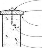
MALLEABLE OR OTHER LARGE WASHER

WEATHER-RESiSTANT WOOD CAP BEVELED ON TOP FOR DRAiNAGE

DRIP CUT iN UNDERSiDE OF cap

anchor bolts at 6 ft. o. c. minimum.

concrete-block OR concrete wall


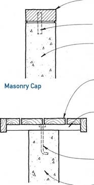
rowlock brick OR paver cap


MASONRY TIES AT 2 FT. O. c.

concrete-block OR concrete wall


WEATHER-RESiSTANT WOOD SEAT NAILED

or screwed TO supports

P. T. 2x OR 4X SuPPORTS BOLTED PERPENDicuLAR TO WALL AT 2 FT. Oc. OR PER capacity OF FINISH SEAT MATERIAL


One-Piece Wood Cap


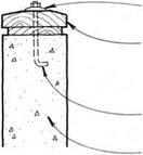
MALLEABLE OR OTHER

large washer

WEATHER-RESiSTANT TWO-PiEcE WOOD cAP; TOP piece beveled & WITH DRIP

anchor BOLTS AT 6 ft. o. c. minimum.

concrete-block OR concrete wall


ANcHOR BOLTS AT 2 FT. O. c. & REcESSED flush into supports

concrete-block or concrete wall


Wood-Bench Cap


Two-Piece Wood Cap


FOUNDATION &amp;amp; STORM DRAINAGEFOUNDATION &amp;amp; STORM DRAINAGEFOUNDATION &amp;amp; STORM DRAINAGE

FOUNDATION &amp;amp; STORM DRAINAGE

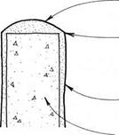
FOUNDATION &amp;amp; STORM DRAINAGEПодпись: Stucco Cap
Подпись: ROUNDED SHAPE PROMOTES DRAiNAGE. STuccO OR WALL CONTINUOUS OVER CAP. FOR STuccO DETAILS SEE 118-119 SILicONE cOATING FOR MOISTURE PROTECTION CONCRETE-BLOCK OR CONCRETE WALL NOTES

THESE DETAILS ARE FOR THE TOPS OF RETAINING WALLS, WHicH ARE uSuALLY ExPOSED TO THE WEATHER. WOOD caps WILL ultimately decay, SO THEY ARE DESIGNED FOR RELATivE EASE OF REPLAcEMENT. THERE IS NOT MucH POINT IN MOiSTuRE BARRIERS, SiNcE THEY WILL ONLY TRAP RAINWATER AGAINST THE WOOD. RETAINING – WALL SuRFAcES SHOuLD BE PROTECTED FROM MOiSTuRE PENETRATION TO PREvENT DAMAGE FROM THE FREEZE – THAW cYcLE. SEAL WITH cLEAR AcRYLic OR SILicONE, OR WATERPROOF WITH MODIFIED PORTLAND-cEMENT PLASTER

or bitumen-modified urethane.

SEE 180
FOUNDATION &amp;amp; STORM DRAINAGEПодпись: Metal Capcontinuous metal cap with drip edge

FASTEN METAL cAP TO WALL AT SIDE TO

prevent moisture

PENETRATION OF TOP FLAT SuRFAcE.

concrete-block OR concrete wall

@ CONCRETE & CONCRETE-BLOCK WALL CAPS
FOUNDATION &amp;amp; STORM DRAINAGE

FOUNDATION &amp;amp; STORM DRAINAGE

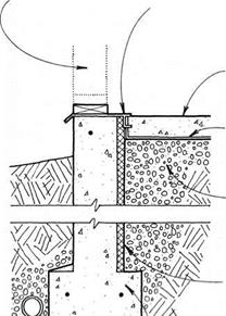
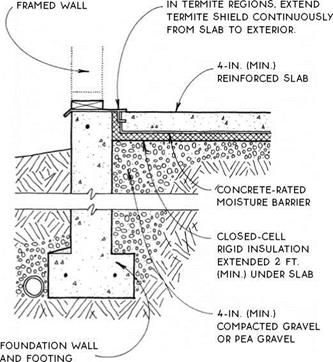
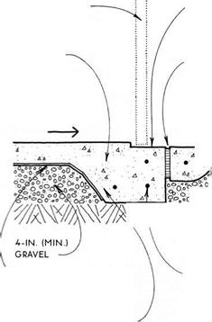
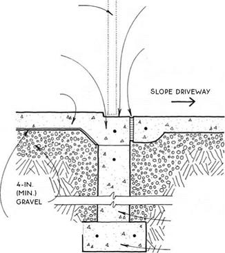
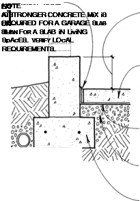
Preparation before pouring a slab is critical to the quality of the slab itself. The primary goals in preparing for a slab are to provide adequate and even support, and to control ground moisture.

Soil—Soil is the ultimate support of the slab. Soil must be solid and free of organic material. Some soils require compaction. In termite areas, the soil is often treated chemically. Verify compaction and soil treat­ment practices in your local area.

Gravel—Gravel is a leveling device that provides a porous layer for groundwater to drain away from the slab. A minimum of 4 in. of gravel is recommended. Gravel must be clean and free from organic matter. Crushed and ungraded gravels must be compacted. Graded gravels such as pea gravel composed entirely of similar-sized round particles cannot and need not be compacted.

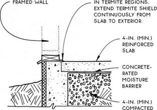
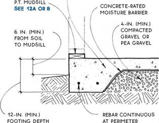
Moisture barrier—Moisture barriers prevent mois­ture (and retard vapor) from moving upward into a slab. Six-mil polyethylene is common and works well in Detail A. Overlap joints 12 in. and tape the joints in

SLABS
areas of extreme moisture. A more substantial concrete-rated moisture barrier is necessary for Detail B because the moisture barrier is in direct contact with the concrete slab. Polyethylene may deteriorate within

CONCRETE

SLAB ‘ ~ …___ ^

A A. . ‘ 4 . • C.

FOUNDATION &amp;amp; STORM DRAINAGE

a very short period in this situation, and it is easily punctured during slab preparation and pouring. A more substantial concrete-rated barrier is a fiber – reinforced bituminous membrane, sandwiched between two layers of polyethylene.

Sand—Sand (shown only in Detail A), allows water to escape from concrete in a downward direction during curing. This produces a stronger slab. The American Concrete Institute recommends a 2-in. layer of sand below slabs.

Welded wire mesh—Welded wire mesh (WWM) is the most common reinforcement for light-duty slabs. The most common size is 6×6 (w1.4 x w1.4)—adequate for a residential garage, which requires a stronger slab than a house. One disadvantage to WWM is that the 6-in. grid is often stepped on and forced to the bottom of the slab as the concrete is poured.

Rebar—Rebar is stronger than welded wire mesh.

A grid of #3 rebar at 24 in. o. c is also adequate for a residential garage.

Fiber reinforcement—Fiber reinforcement is a re­cent development in slab reinforcement. Polypropylene fiber reinforcement is mixed with the concrete at the plant and poured integrally with the slab, thereby elim­inating difficulties with placement of the reinforcing material. The addition of 1.5 lb. of fiber per cubic yard of concrete produces flexural strength equal to WWM in a slab. The appearance of the slab is affected by the presence of fibers exposed at the surface.

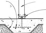
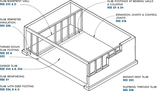
Expansion joints—Expansion joints allow slabs to expand and contract slightly with temperature changes. They also allow slabs to act independently of building elements with which they interface. Expansion joints are appropriate at the edges of slabs that are not heated (not in the living space) or that, for some other reason, are expected to change temperature significantly over their lifetimes. Expansion joints are also used to isolate building elements that penetrate slabs such as struc­tural columns, walls, or plumbing (see 25B).

Control joints—Control joints induce cracking to occur at selected locations. They are troweled or cut into the surface of a slab to about one-quarter of the slab depth and at 20-ft. intervals. Cold joints, which automatically occur between sections of a slab poured separately, can act as control joints.

Подпись: CONCRETE-SLAB JOiNTSCONCRETE-SLAB REiNFOROiNG

backfill & DRAiNAGE


waterproofing SEE 18C

BASEMENT WALL

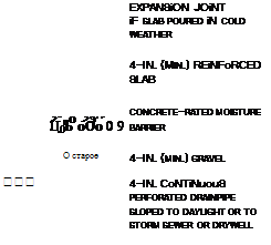
bituminous expansion joint or leave 1-iN. space between SLAB & WALL To relieve excess hydrostatic pressure from below slab

4-IN. (Min.) reinforced slab

concrete-rated moisture barrier

6-IN. (Min.) gravel


WATERPROOFiNG SEE 18C

BASEMENT WALL


BACKFiLL & DRAiNAGE SEE 18B


FOUNDATION &amp;amp; STORM DRAINAGE

O*o X О rv о0


4o°§Oo

0O°oOn0° о о о 0 ° OoOoQO о °o ° о О °0 ООол<

О о о О, Уо і


00°С> а 0ОрО


4-IN. CoNTiNuouS

perforated drainpipe sloped to daylight or to storm sewer


FOUNDATION &amp;amp; STORM DRAINAGEFOUNDATION &amp;amp; STORM DRAINAGEFOUNDATION &amp;amp; STORM DRAINAGEFOUNDATION &amp;amp; STORM DRAINAGE

FOUNDATION &amp;amp; STORM DRAINAGE

SLAB/BASEMENT WALL

SLAB/BASEMENT WALL

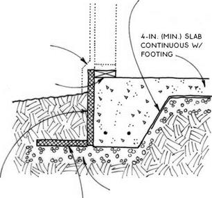
4-IN. (MiN.) REiNFORCED SLAB CONTiNUOUS WITH FOOTING

FOUNDATION &amp;amp; STORM DRAINAGE

NOTE

an uninsulated & exposed perimeter slab IS appropriate ONLY For uNHEATED spaces or in very warm climates.

NOTE

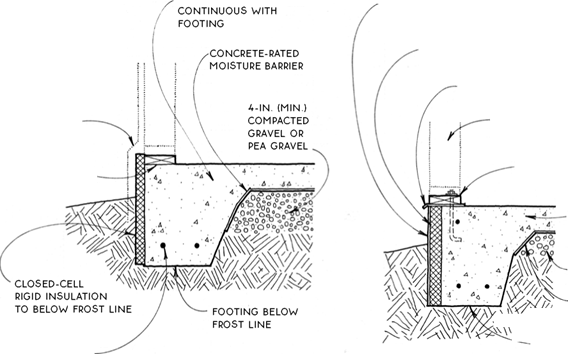
SLABS LOSE HEAT MOST READILY AT THEIR PERIMETERS. WHERE THEY ARE EXPOSED TO THE AIR. SO SLABS MUST BE PROTECTED FROM HEAT LOSS BY A CLOSED-CELL RIGID INSULATION PLACED AT THEIR EDGES. THE AMOUNT OF INSULATION REQUIRED WILL DEPEND ON THE CLIMATE AND ON WHETHER THE SLAB IS HEATED.

THE POSITION OF THE INSULATION WILL DEPEND PRIMARILY ON THE FOUNDATION ТУРЕ. SLABS INTEGRAL WITH TURNED-DOWN FOOTINGS ARE INSULATED AT THE OUTSIDE BUILDING EDGE. SLABS WITH DEEP FOOTINGS ARE OFTEN INSULATED AT THE INSIDE FACE OF THE FOUNDATION. ALTHOUGH THEY MAY ALSO BE INSULATED AT THE OUTSIDE BUILDING EDGE.

FOUNDATION &amp;amp; STORM DRAINAGE

turned-down deep footings

Footings SEE 23A, B & D

SEE 220 & D, 230

SLAB WITH TURNED-DOWN FOOTING

Warm Climate, Well-Drained Soil


SLAB PERIMETER INSULATION


4-IN. (MIN.) SLAB


FOUNDATION &amp;amp; STORM DRAINAGE

WALL FINISH:

STuCCO-WRAppED

insulation

OR SIDING

stopped at top of insulation

WITH FLASHING

& protective

COATING OVER

insulation


TERMITE SHIELD IF REQuiRED


FRAMED WALL pROJECTED OVER INSuLATION AND COATING


p. t. mudsill SEE 12A OR B


p. t. mudsill SEE 12A OR B


FOUNDATION &amp;amp; STORM DRAINAGE

REBAR CONTINuOuS

at perimeter


FOUNDATION &amp;amp; STORM DRAINAGEFOUNDATION &amp;amp; STORM DRAINAGE

FOUNDATION &amp;amp; STORM DRAINAGE

SLAB WITH TURNED-DOWN FOOTING

Insulation Outside Framing

SLAB WITH TURNED-DOWN FOOTING

Insulation Flush with Framing

Подпись:Подпись:Подпись: 4-IN. (MIN.) REINFORCED SLABПодпись:Подпись:FOUNDATION &amp;amp; STORM DRAINAGEFOUNDATION &amp;amp; STORM DRAINAGE

FOuNDATION wALL And FOOTING

closed-cell RiGiD iNSuLATiON TO BELOw Frost LiNE OR 2 Ft. (MiN.)

SEE 22B

A SLAB ON GRADE/DEEP FOOTING

Vertical Interior Insulation

SLAB ON GRADE/DEEP FOOTING

Horizontal Interior Insulation

concrete-rated

MOiSTuRE BARRiER


flashing & protective coating over insulation


p. t. mudsill SEE 12A OR B


gravel OR pea gravel


vertical closed-cell rigid insulation


4-in. (min.) compacted gravel or pea gravel


closed­cell rigid insulation TO below FROST LINE OR 2 ft. (MIN.) SEE 22B


NOTE

required dimensions & r-value of insulation vary w/ climatic zone.


horizontal closed­cell rigid insulation


FOUNDATION &amp;amp; STORM DRAINAGEFOUNDATION &amp;amp; STORM DRAINAGEFOUNDATION &amp;amp; STORM DRAINAGE

FOUNDATION &amp;amp; STORM DRAINAGE

SLAB WITH TURNED-DOWN FOOTING

Frost-Protected Shallow Footing

SLAB ON GRADE/DEEP FOOTING

Vertical Exterior Insulation

recessed threshold cast into slab TO control water

caulked expansion

JOINT


GARAGE DOOR


GARAGE DOOR


recessed threshold cast

INTO SLAB TO

control water caulked

expansion joint


4-IN. (MiN.) REiNFORCED SLAB SEE 21A


thicken slab edge at foundation connection & TIE with rebar


SLOPE SLAB TOWARD DOOR AT 1/8 In. pER Ft.


4-IN. (MIN.)

reinforced slab SEE 21A


slope driveway AWAy from building

—>


FOUNDATION &amp;amp; STORM DRAINAGE

gravel


concrete-rated moisture barrier


REBAR

continuous at perimeter


FOUNDATION &amp;amp; STORM DRAINAGE

foundation

WALL


FOOTING

continuous with slab SEE 22c


FOOTING


TURNED-DOWN FOOTING

At Garage Door


FOUNDATION &amp;amp; STORM DRAINAGE

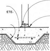
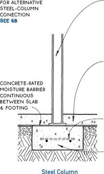
NOTE


WOOD pOST


REBAR


STEEL cOLuMN WITH STEEL BEARING pLATE AT BOTTOM BEARS ON FOOTING.


concrete

RATED

moisture

BARRIER


galvanized STEEL column base

SEE 6B


p. T. SILL plate NAILED TO SLAB WITH concrete NAILS

30-LB. FELT uNDER p. T. SILL


mmwmm

Wood Post


reinforced SLAB poured around column locks column in place.


REBAR

concr

RATED

moisture

BARRIER


NOTE

DEpTH & FLAT BEARING SuRFAcE OF FOOTING MuST BE

sized to support vertical LOADS.


REBAR


independent column FOOTING under slab


Bearing Wall


INTEGRAL SLAB FOOTING

Wood Post & Bearing Wall


FOUNDATION &amp;amp; STORM DRAINAGE

FOUNDATION &amp;amp; STORM DRAINAGEFOUNDATION &amp;amp; STORM DRAINAGEFOUNDATION &amp;amp; STORM DRAINAGEFOUNDATION &amp;amp; STORM DRAINAGEFOUNDATION &amp;amp; STORM DRAINAGE

FOUNDATIONS

FOUNDATION &amp;amp; STORM DRAINAGE FOUNDATION &amp;amp; STORM DRAINAGE FOUNDATION &amp;amp; STORM DRAINAGE

Utilities

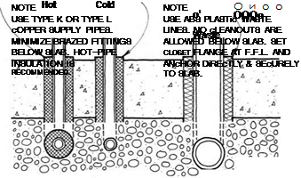
A GARAGE SLAB/FQUNDATIQN WALL ҐВ PLUMBING THROUGH SLAB
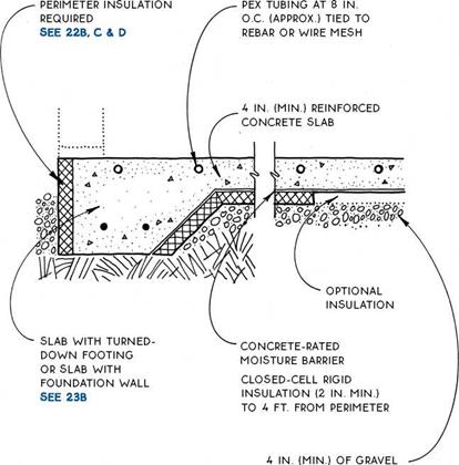
FOUNDATION &amp;amp; STORM DRAINAGENOTE

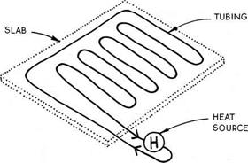
cROSS-LiNKED POLYETHYLENE TUBING (PEX) HAS REPLAcED cOPPER TUBING AS THE cONvEYOR OF HOT WATER FOR RADIANT SLABS. THIS ELASTic TUBING IS SUPPLIED IN LONG ROLLS & cAN cOvER ABOUT 200 SQ. FT. WITHOUT ANY JOINTS BELOW THE SURFAcE. THE ADDITION OF INSULATION BELOW THE SLAB WILL IMPROvE THE PERFORMANcE OF THE SYSTEM.

FOUNDATION &amp;amp; STORM DRAINAGE

Diagram of Radiant Heat Tubing

RADIANT-HEAT SLAB

chapter

POWER TOOLS

POWER TOOLS

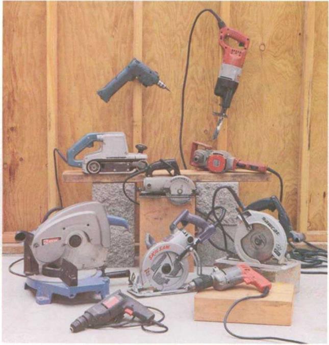
Power tools have revolutionized the way houses are built. Some of the tools common on the job site include (clockwise from bottom) 3/s-in. drills, miter saws, belt sanders, cordless drills, reciprocating saws, У2-ІП. drills, trim saws, and circular saws (worm drive left, sidewinder right).

Tools aren’t like stretch socks where one size fits all. A saw that has the right combination of power, weight, and feel for one carpenter may be the wrong choice for another. But here are a few tips that should help you make an educated choice when it comes time to invest in a power tool.

• The tool should be comfortable to use, so (if pos­sible) try before you buy. Do some homework, and try out a few to see how each one feels.

POWER TOOLS

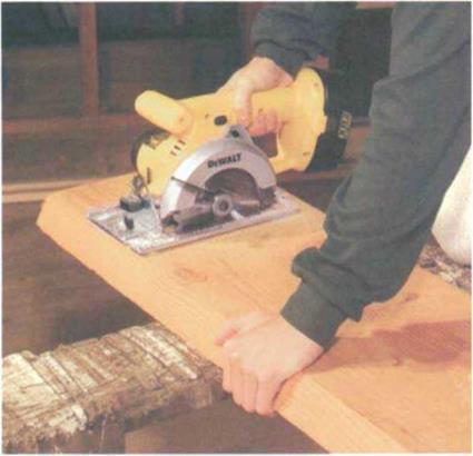
An 18-volt cordless circular saw can make short work of 2x stock.

• I also recommend asking people who use tools daily—like other carpenters or contractors—which models and makes they prefer. For these folks, dura­bility is a big issue, and they won’t mind telling you which tools have lasted and which ones haven’t. It also helps to read magazines that research and evaluate different tools (Fine Homebuilding maga­zine is a good place to start).

• Buy the best quality you can afford. In general, steer away from homeowner-grade tools, which won’t stand up to heavy-duty job site use. Professional-grade tools cost more, but they are more durable, more powerful, and easier and safer to use than homeowner grade.

• Many portable power tools are available in cord­less versions with rechargeable batteries. The first cordless tools I used years ago were actually play­things for those who loved gadgets. This is no longer true. Today’s cordless tools are used by pro­fessional workers in every trade. These tools have plenty of power and allow carpenters to move around the job site without the frustration of having to pull an extension cord around behind them.

• Almost every carpenter I know uses a cordless drill/screwdriver daily. In addition, now there are cordless jigsaws, reciprocating saws, and circular saws that have enough power for daily professional use. The new 18-volt systems have enough juice to power a cordless saw through 2x stock, and with a spare battery and charger on site, the only break you’ll have to take is for lunch.

The first time I had my hands on a circu­lar saw was in 1951, when power tools were first becoming readily available. What a sense of wonder it gave me. That stack of framing lumber that used to take me hours to cut with a handsaw could now be cut in minutes with the circular saw I was holding.

In my lifetime, carpenters have gone from building an entire house in a few months using hand tools to building the same house in a matter of weeks—even days in some cases—using power tools. The power-tool revolution has changed how carpenters work. Today, power tools are used in every aspect of carpen­
try, so one of the tasks of a beginning carpenter is to learn a little bit about these tools, including how to choose them and how to use them safely.

In this chapter I’ll focus on the most common tools used on the job: circular saws, portable table saws, miter saws, reciprocating saws, jigsaws, drills, pneu­matic nailers, routers, and sanders. Because practice is essential to gaining familiarity with any tool, at the end of the chapter I’ll give you plans and instructions for building a workbench using some of the power tools discussed in the chapter.

Techniques ADJUSTING THE MUDSILL TO FIX FOUNDATION WALLS

Techniques ADJUSTING THE MUDSILL TO FIX FOUNDATION WALLS

But here’s some good news: If von know how far off it is, yon can usually make the appro­priate corrections when installing the sills (see the sidebar on the facing page). It’s worth it to make the sills as straight, parallel, square, and level as possible. Otherwise, the mistakes made at this preliminary stage tend to become even more troublesome further down the line. Here’s how to check the foundation:

Подпись: USING A WATER LEVEL
Подпись: Clear plastic
Подпись: This side of the foundation is Уг in, lower than the other side.
Подпись: A simple v/ater level can be used to check the foundation for level. These are available at home improvement centers.
Techniques ADJUSTING THE MUDSILL TO FIX FOUNDATION WALLS

Подпись:

STRAIGHT. Check the walls for straightness bv stretching a dry line (string) from comer to corner. At this point, you just need to know­how straight the top outside edge of the foun­dation is, because you’ll be measuring in from this edge to locate the sill.

PARALLEL. Measure across the walls at both ends and in the middle. All three measure­ments should be the same. 1 use ‘/ in. over 20 ft. as the tolerance limit for parallel.

SQUARE. Plus or minus lA in. over 20 ft. is the tolerance that I use for square walls. You can check any rectangular foundation for square simply by comparing the diagonal measure­ments, which should be equal. When that isn’t possible, use the 6-8-10 rule to check for square corners. Measure 6 ft. in from a corner on one side and 8 ft. on the other side (see the photo above). Then measure between those two points. If the corner is square, the

Techniques ADJUSTING THE MUDSILL TO FIX FOUNDATION WALLS Techniques ADJUSTING THE MUDSILL TO FIX FOUNDATION WALLS Techniques ADJUSTING THE MUDSILL TO FIX FOUNDATION WALLS

POSITIONING SILLS ON THE FOUNDATION

ABC

Sill plates can be set flush with the edge of the foundation (A) and the siding nailed directly to the walls. When sheathing the house frame with OSB or plywood, though, hold in the sill plates l/z in. (B). When using rigid foam to insulate a basement or a crawl space (C), position the plates so that the outside face of the sheathing is in plane with the outside face of the foam.

Techniques ADJUSTING THE MUDSILL TO FIX FOUNDATION WALLS

hypotenuse of the triangle should be 10 ft. For smaller buildings, 3 ft. on one side and 4 ft. on the other should yield a 5-ft. hypotenuse. On a large building, use measurements of 12 ft.,

16 ft., and 20 ft.

LEVEL. 1 like to check a foundation for level with a builders level (especially one with a laser beam) set on a tripod. If you don’t have one of these available, an inexpensive water level will work fine (see the illustration on p. 33). The walls should be level to within Vi in. over 20 ft.

Determine the sill’s position

Depending on what you find after measuring the foundation as described above, you mav

4 4

need to adjust the sills position using some of the techniques explained in the sidebar on
p. 34. The sill plates are often bolted flush to the outside of the foundation, but there are variations vou may want to consider (see the illustration above). For example, when the walls will he sheathed with З-in. plywood or OSB, it’s best to hold the plates V: in. inside the foundation. This puts the sheathing (lush with the foundation and allows the siding to lap down over the concrete.

The sills must be installed along snapped layout lines on lop of the foundation walls. (If you’re building on a slab, the layout lines will be on top of the slab.) The lines identify where the inside edge of the sill will fit.

Taking the width of the sill lumber into account (3V: in. for a 2×4 sill, 3/ in. for a 2×6), snap chalklines around the perimeter to indi­cate the inside edge of the sill (see the photo on p. 34). Make slight adjustment in the posi­
tions of the chalklines, if necessary, so that the sill is straight, square, and parallel.

Locate and drill bolt holes

Anchor holts sometimes come out of the foundation at odd angles. You can straighten bent bolts with a length of pipe, as shown in the photo at right. Then set long, straight, pressure-treated sill hoards in place for mark­ing and drilling. You can use a square and a tape measure to lay out the bolt hole locations on the sills, but it’s a lot faster to mark the hole locations with a boll marker (see the photo below). You can make a bolt marker or buy a ready-made version (see the illustration on p. 58 and Resources on p. 278). To use this layout tool, place each plate directly on the inside of the chalkline.

Techniques ADJUSTING THE MUDSILL TO FIX FOUNDATION WALLSOnce the bolt locations are marked, set the sill plates on blocks of wood or sawhorses and drill the holes. Use a T-in. bit to make holes for Tin. bolts. For X-in. bolts, use a /Tin. bit.

Подпись: .. -. ЖвяЯШЯШк* V&BA -. A LONG PIPE STRAIGHTENS A SHORT BOLT. A length of l-in.-dia. pipe straightens any bolts that may have been bent during (or since) the foundation pour. [Photo Roger Turk.]

A BOLT MARKER COMES IN HANDY. Use a bolt marker to transfer the bolt locations to the sills so you can drill the bolt holes accurately. [Photo by Roe A. Osborn, courtesy Fine Homebuilding magazine. The Tciinton Press, Inc.]

Designing a Gradation Curve

Some hold the opinion that the best gradation curve is the one passing exactly in the middle of the space between the upper and lower gradation limits. To a certain extent in some cases this may be true; however, in the majority of cases it is not. The shape of a design gradation curve exerts a significant impact on mix properties. For example, by looking at its shape, one may determine if the mix is more or less coarse or has the probability of being overfilled with mastic. Therefore the shape of a design gradation curve is not an unimportant question.

The subsequent phases of design will be discussed later, starting with the coarse aggregate fraction, going through the sand fraction, and ending with the filler content. A familiarity with the basic rules of designing aggregate mixes, including the algorithm and calculations, is assumed. To brush up on these rules, refer to a basic text, such as The Asphalt Handbook (MS-4), a publication of Asphalt Institute.

The qanats: a new technique for obtaining water

When surface water cannot meet the needs of irrigation, one must tap groundwater. It was probably at the beginning of the Ist millennium BC, in Persia or in neighbouring lands, that a remarkable device for obtaining high quality water was invented: the qanat.[80]

This word means “reed” in Akkadian. The device comprises a gallery, or shaft, dug nearly horizontally from the flank of a natural slope back into the aquifer, but with a small slope (of the order of one or two per thousand) so that the water can flow out by gravity (Figure 2.19). In general, the construction of a qanat begins with the drilling of what will become its terminal well, called the “mother well”, through which the nature and level of the water table can be determined. Then the excavation of the gallery begins from the downstream end, making it possible to work in the dry until the aquifer is reached; this excavation thus proceeds all the way to the mother well. Intermediate wells, normally spaced at from 50 to 100 meters, provide for removal of the spoil from

The qanats: a new technique for obtaining water

Figure 2.19 Principles of the qanat: a technique for mining groundwater, apparently first appeared in Urartu (Armenia) in the 8th century BC, and then spread throughout the Persian Empire (Goblot, 1979).

the gallery, and provide for ventilation. The gallery can be several kilometers long, even reaching ten or more; the mother well can be the order of twenty to a hundred meters deep. The flow delivered by the qanat is generally from several, to several hundred, liters per second.

In 714 BC, Sargon II, king of Assyria (and the father of Sennacherib), is at war with king Rusa I of Urartu. He destroys the outposts of Urartu in the region of the lake of

Urmiah, as well as the qanats supplying water to the city of Ulhu, located to the east of this lake (60 km to the north of present-day Tabriz). The Assyrians, in a written account of this campaign, leave us an admirable description of the devices called “water outlets” that could comprise the first written evidence of the qanats:

“Ursa (i. e. Rusa) the king and lord of this land, pushed by his intelligence, showed his peo­ple how one manages the water outlets and creates a flow of water as copious as that of the Euphrates”.[81] [82] [83]

What is the genesis of this innovation? The Zagros mountains are a region of mines, especially in the area around the lake of Van. According to Henri Goblot, it was neces­sary to provide gravity drainage – to the surface – of certain mine shafts that were flood­ed after having pierced aquifers. In a country faced with the need to augment its water resources, the idea of making use of this drained water, and then to dig galleries express­ly for this purpose, surely picked up speed rapidly. The idea had a grand future: the Persians adopted it to develop the Iranian plateau, and in particular to provide water for their capital, Ecbatane. This is reported by Ctesias of Cnidus, a doctor of Xenophon’s expedition who was long held captive by the Persians:

“Having arrived at Ecbatane, a city located in a plain, she (again the legendary Semiramis! Here, it can only be a Mede or Persian sovereign) built a luxurious palace and she watched over the entire region with great care. The city was without water and there were no springs

in the vicinity; but Semiramis brought water to all the city, abundant and very pure water

52

thanks to her heavy investments.”

Cyrus brought the technique of qanats to Oman, and Darius brought it to the oases of Egypt. As we will see in subsequent chapters, the Romans developed the technique in all of the Near East, and as far as Tunisia, and the Arabs took it to Spain and Morocco. Migrants coming from the East brought it to the benefit of Saharan oases.

DESIGNING AN AGGREGATE MIX BY. APPLYING GRADATION LIMITS

The application of gradation limits has become the most commonly used method for designing SMA mix composition. This method involves gradation analyses of all the constituent aggregates, including the filler, followed by balancing the proportions of all the aggregates in such a way that the ultimate gradation curve is situated between the adopted gradation limits. Used alone, it is a very simple method. Unfortunately it is characterized by some drawbacks that may result in a poor SMA mix design.

The advantages of the method of gradation limits include the following:

• The method is simple to use and quick to produce results. After the grada­tion analyses of the constituent materials are carried out, the proportions of the mix constituents can be quickly calculated simply by using computer software. It is also easy to relocate the gradation curve by manipulating the percentages of the constituents. However, for the very experienced engineer there are better ways to analyze and predict the behavior of the mix.

The disadvantages of this method are as follows:

• The position of a gradation curve inside gradation limits does not absolutely secure an appropriate design of an aggregate mix. For example, the grada­tion curve graph itself is not enough to predict and secure both a suitable aggregate skeleton and the impact of flat and elongated particles.

• Some major or minor errors occur in volume relations of constituent materi­als when using only mass units to show the gradation. If the method does not stipulate this, differences in densities of constituents are not taken into consideration. Significant differences in aggregate densities produce sub­stantial differences in the volume relations of a mix. This is not apparent on a gradation curve if it shows the weight distribution retained on sieves, though it can obviously be solved by presenting the gradation in terms of volume units.

• It is presupposed that gradation limits illustrate the area of an appropriate gradation. However, as practice proves, the limits of a suitable gradation should also be periodically verified and mistakes corrected.

In summary, it is safe to say that relying only on the method of gradation limits leads to designing SMA with a low degree of reliability of performance. In Chapter 7, some SMA design methods are discussed, with the application of some concepts extending beyond the use of gradation limits.