Service Station Drives

Service station drive approach geometry is probably the most complex of any drive design. Many of the geometric features may be used in the design of other commercial

–у* I—w-12’* —14’ж |—-

Service Station Drives


NOTES

GENERAL’. The design details shown hereon shall govern the constraction of driveways unless otherwise shown in /he project pton$.

The pavement type and l hickness Shalt be specified In the project plans.

Driveway ond malt box approaches shall be combined when feasible.

JOINTS: impressed Joints for

portlond cement concrete drive­ways shall be minimum width by J" і depth and shall be seated with 705 01 or ASTM 0 ‘850.

In addition lo the Joints shown hereon. Impressed Joints without tie bars sholi be placed in portlond cement concrete driveways ot Intervals not to exceed seventeen feel In the portion of the driveway back of the flare.


TYPE I DRIVEWAY


Подпись: 185

COMBINED DRIVEWAY & MAIL BOX APPROACH


TYPE 2 SKEWED DRIVEWAY

Transition from standard curd section to drop curb section to be made In 18" distance from driveway.

s—Dr ivewgy


BUREAU OP LOCATION AND DESIGN OHIO DEPARTMENT OF TRANSPORTATION

DRIVEWAYS

0 Ate

2-2i-SZ

c‘"x?£’h bp-4.1

iPPRnven^X fur. R.. 1 * 0


Service Station Drives

** Add J feet і or coch additional mall box

TYPICAL MAIL BOX APPROACH


Service Station DrivesService Station DrivesService Station DrivesService Station DrivesService Station Drives

Service Station Drives

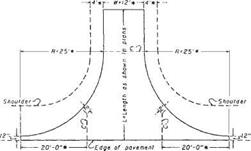
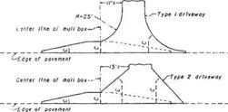
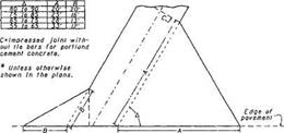
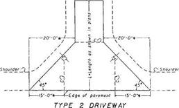
FIGURE 2.50 Details of driveway designs. Conversions: 1 ft = 0.305 m, 1 in = 25.4 mm. (From Location and Design Manual, Vol. 1, Roadway Design, Ohio Department of Transportation, with permission)

and industrial drives. Figures 2.52 through 2.55 illustrate service station approach designs under varying conditions.

The location and angle of an approach in relation to an adjacent highway intersection should be such that a vehicle entering or leaving the site may turn out of or into the nearest lane of traffic moving in the desired direction and be channeled within this lane before entering the intersection or proceeding along the highway. The interior angle between the axes of dual approaches and the centerline of the roadway should fall between 45 and 90°. This interior angle should fall between 70 and 90° for single approaches designed for two-way operation. The width of all approaches should not be greater than 35 ft (11 m) in the throat of the approach measured at right angles to

Подпись: ISOMETRIC VIEW

Подпись: Various Gutter Slopi Up to t'/ft. ' . и Подпись: Use Grade Controls (Drive Details *l)

Service Station Drives
Подпись: ALTERNATE: DRIVE WITHOUT CURB
Подпись: ISOMETRIC VIEW
Подпись: Use Grade Controls (Drive Details *)

Service Station DrivesEXAMPLE: TREE LAWN AND WALK, LESS THAN 6′ WALK DEPRESSED Г

RESIDENTIAL DRIVEWAY PROFILES

LESS THAN 6′ TREE LAWN

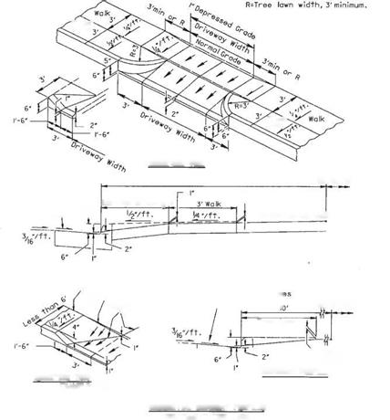
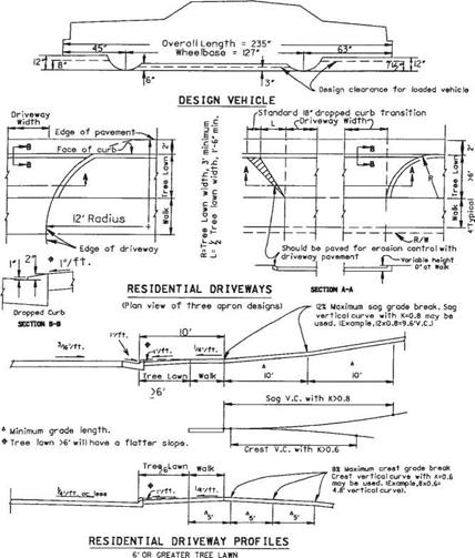
FIGURE 2.51 Additional details of driveway designs. Conversions: 1 ft = 0.305 m, 1 in = 25.4 mm. (From Location and Design Manual, Vol. 1, Roadway Design, Ohio Department of Transportation, with permission) the axis of the approach. Where public alleys adjoin the service station property, approaches may begin at the far side of the alley, and if so used, the width of the alley should be included as part of the approach opening.

Approach radii on uncurbed highways should be as follows:

Turning radii: 15 ft (4.6 m) minimum, 25 to 50 ft (7.6 to 15.2 m) desirable Nonturning radii: 5 ft (1.5 m) minimum, 10 ft (3.0 m) maximum

Approach radii on curbed highways should be as follows:

Turning radii: 3 ft (0.91 m) minimum, 15 to 25 ft (4.6 to 7.6 m) desirable Nonturning radii: 3 ft (0.91 m) minimum, 5 ft (1.5 m) maximum

L 15′ or greater W 35′ maximum
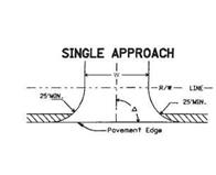
Service Station DrivesЛ 70° to 90° (for approach with two-way operation) – O 45° to 90°

R’ Nonturning Radius,

5′ min. to!0′ max R" Turning Radius, 15’min,

25’to 50’Desirable r Permissible Rounding 15’max ч\\ Treated Shoulder

Service Station Drives
DUAL APPROACHES & INTERMEDIATE ISLAND

Where the approach radius controls the turning radius of a right-turning vehicle entering the service station from the adjacent traffic lane of the roadway, the radius of that edge should be as long as practical to provide a free and safe movement.

Compression and Tension in Beams

Beam is a good catch-all word to identify a (usually) horizontal timber whose job it is to carry a load across a span. Girders and floor joists are common specific examples, as are lintels over doors and windows. Even though many roof rafters are pitched to some degree, they perform as beams, too, although other thrust considerations come into play.

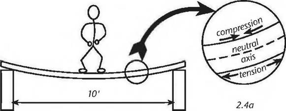
Let’s load a simple but imaginary beam to see how it works. We’ll make it a rather flimsy beam so that its exaggerated performance will show what’s happening. Imagine a 12-foot long two-by-eight plank spanning — flatwise — from one support to another. If the ends of the plank are each bearing on a foot­wide concrete block, the clear span between supports is ten feet. Now I’ll step on to the center of this “beam,” rather carefully, with my 170-pound weight. Obviously, the plank sags in the middle, and quite a bit. But it probably doesn’t break, even though it has me a little worried. What is happening is that the

underside of the plank is being stretched under my weight; that is, it is in tension. At the same time, the molecules on the top surface of the plank are trying to crush together; it is in compression.

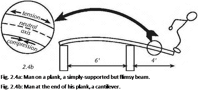
image12Подпись: Fig. 2.4a: Man on a plank, a simply-supported but flimsy beam. Fig. 2.4b: Man at the end of his plank, a cantilever. Allowing that this is true — and it is — it follows that an imaginary line along the center of the planks thickness is neither in compression nor tension. This line is known as the centroid or the neutral axis. See Fig. 2.4.

An imaginary beam as here described would be very springy, somewhat like a trampoline. Move one of the supports inward four feet, and we are on the way to

inventing both the cantilever and the diving board. Interestingly, when the beam is cantilevered by placing my weight at its free end, the top surface is now in tension and the bottom surface is in compression.

Instinctively, we know that to lay a “beam” flat like this is — well — stupid. Obviously, if the plank were rotated 90 degrees along its transverse axis — so that it looks like a proper floor joist — it would be very much stronger against bending pressures. It would feel quite stiff to walk along, providing I could maintain my balance for 10 feet. We may think that we know this instinctively, but I submit that it is a matter of our experience more than instinct.

Physical and Chemical Characteristics

This section describes how the material be­haves. The information is useful for the design of ventilation systems and for providing ade­quate equipment and procedures for fire and spill containment.

• Vapor pressure tells you how much vapor the material may give off. A high vapor pressure indicates that a liquid will easily evaporate.

• Vapor density refers to the weight of the pure gaseous form of the material in rela­tion to air. The weight of a given volume of a vapor (with no air present) is compared with the weight of an equal volume of air.

• Specific gravity tells you how heavy the material is compared to water and whether it will float or sink.

• Evaporation rate refers to the rate at which a material changes from a liquid or solid state to its gaseous form.

• Volatile organic compounds (VOCs) pro­vide you with an idea of the degree to which the substance will outgas. If the ma­terial is toxic, the degree of volatility would be important to consider.

• Water reactivity indicates whether the chemical reacts with water to release a gas that is flammable or presents a health haz­ard.

• Appearance and odor indicate how a prod­uct is supposed to look and smell. For ex­ample, if the product is supposed to be clear and odorless but arrives onsite with

Section III — Physical Characteristics

Boiling Range:

>369°F

Vapor Pressure (mm Hg.):

125mm Hg @ 100° F

Specific Gravity (H20=1):

1.1 -1.3

Vapor Density (Air = 1):

> 1

% Volatile (Volume):

< 1%

Evaporation Rate (BuAc = 1):

> 1

Volatile Organic Content (VOC):

3.8 Ib./gal.

Solubility

(specify solvents):

Miscible in water, alcohol, acetone, some glycol ethers; insoluble in petro­leum hydrocarbons

Appearance and Odor:

Clear, odorless liquid

NOTE: In the above M5DS, the evaporation rate is compared with the evaporation rate for butyl acetate. With this particular product, the evaporation rate is less than that for butyl acetate.

Product #2 TABLE 1.6

Section III — Physical/Chemical Characteristics

Boiling Point:

HCFC-22

-41.4° F at 1 ATM

Polyurethane resin

NE

Vapor Pressure:

HCFC-22

136 psia at 70° F

Vapor Density (AIR = 1):

HCFC-22

2.98 at 1 ATM

Specific Gravity (H20=1):

Polyurethane resin

1.1

Solubility in Water:

Insoluble, reacts with water

Appearance and Odor:

Gel under pressure. Faint ether-like odor.

NOTE: Hydrochlorofluorocarbons, or HCFCs, are fluorinated carbons that are harmful to the ozone layer.

Product # 1 TABLE 1.7

Section IV — Fire and Explosion Hazard Data

Flash Point (Method Used):

Nonflammable

Flammable Limits (% in air):

Nonflammable

Extinguishing Media:

Nonflammable

Special Fire Fighting Procedures:

Nonflammable

Unusual Fire and Explosion Hazards:

None known

Reactivity:

Stable

Conditions to Avoid:

Avoid extreme heat

Hazardous Polymerization:

May Not Occur

Conditions to Avoid:

None known

Incompatibility (Materials to Avoid):

None known

Hazardous Decomposition or Byproducts:

None known

Section IV — Fire and Explosion Hazard Data

Flash Point:

Polyurethane Resin >400° F

Extinguishing Media:

Water fog, foam, C02, or dry chemical

Fire Fighting Procedure:

Wear self-contained breathing apparatus and turnout gear. Hazardous decom­position products include CO, C02, NO, and traces of HCI. Cured foam: Wear self – contained breathing apparatus. Hazardous decomposition products include CO, C02, NO, and traces of HCI.

Usual Hazards:

Temperatures above 120° F will increase the pressure in the can, which may lead to rupturing. Cured foam:This product will burn. Do not expose to heat, sparks, or open flame. This product is not intended for use in applications above 250° F (121° C). Always protect foam with approved facings. This product is not a FIRE STOP or FIRE BARRIER penetration sealant.

Section V — Reactivity Data

Stability:

Stable under normal storage and handling conditions. Do not store above 120° F. Cured foam will deteriorate when exposed to UV light.

Incompatibility:

Water, alcohols, strong bases, finely powdered metal such as aluminum, magne­sium, or zinc, and strong oxidizers.

Conditions/Hazards to Avoid:

Contamination with water may form C02. Avoid high heat, i. e., flames, extreme­ly hot metal surfaces, heating elements, combustion engines, etc. Do not store in auto or direct sunlight.

Подпись: an acrid smell and/or appears cloudy, the product may be contaminated. Fire and Explosion Hazard Data The flash point tells you the minimum tem-perature at which a liquid will give off enough flammable vapor to ignite. Obviously, the more stable the product, the safer it will be. Reactivity Hazard Data This section can provide you with clues regarding the toxicity of a product. Product #1 is stable (not reactive), with no incompatibility with other products and without hazardous decomposition or byproducts. Product #2 is unstable when exposed to ultraviolet light and high heat and is incom-patible with many substances. Подпись: Health Hazard Data This section provides useful information that will help you determine the toxicity of the product in question. Examining the health hazard section for Product # і would provide reassurance. The product appears to be only an irritant, with no known long-term health effects. (Of course, an edible product would be the ultimate assurance of product safety!) In contrast, the information below on Product #2 is not at all reassuring. This product is known to be carcinogenic, mutagenic, and teratogenic. It also may cause irreversible asthma, allergies, and other damage to the immune system. Although this product volatilizes quickly, workers who install it are exposed to extreme health hazards.

Подпись: Safe Handling Precautions and Leak Procedures This section offers more clues regarding the safety of the product. The fewer the precautions given, the more reassuring the information. Control and Preventive Measures This section lists the personal protective equip-ment that must be used, the type of ventilation to be used, and precautions to be taken when using the material for its intended purpose. Product #1 requires no special protective Подпись: clothing or equipment, which is an indication of product safety. For Product #2, good ventilation and pro-tective clothing over the entire body, including a face shield or goggles, are necessary. The above MSDS examples demonstrate that the information supplied in the MSDS, although incomplete, is nevertheless useful. An MSDS allows you to obtain a general impression about the level of toxicity of many products you may consider using in home construction.

Product #1 TABLE 1.9

Section V — Health Hazard Data

Route(s) of Entry:

Eye contact, inhalation, ingestion

Acute Health Effects:

Eye contact: May cause redness or irritation

Inhalation:

N/A In sufficient doses may cause gastrointestinal irritation

Skin contact:

N/A

Chronic Health Effects:

Not listed as a carcinogen by the NTP, IARC, or OSHA; no adverse long­term effects are known.

Medical Conditions Generally Aggravated by Exposure:

No adverse long-term effects are known.

Emergency & First Aid:

Eye contact: Wash with clean water for at least 15 minutes. If irritation persists, get medical attention.

Inhalation:

N/A

Ingestion:

if irritation persists, get medical attention.

Skin contact:

N/A

Product #2 TABLE 1.10

Section VI —- Health Hazard Data

Toxicology Test Data:

MDI:

Rat, 4 hr inhalation LC 50 — Aerosol 490 mg/m3 — highly toxic

Rat, 4 hr inhalation LC 50 — Vapor 11 mg/l — toxic

Rat, oral LD 50 — > 10,000 mg/kg — practically nontoxic

Rat, inhalation oncogenicity study — @ ~0.2,1, 6 mg/m3; URT irritant; carcinogenic @ 6 mg/m3

HCFC-22:

Rat, 2 hr inhalation LC 50 — 200,000 ppm

Section VI — Health Hazard Data

Acute

Overexposure

Effects:

Eye contact with MDI may result in conjunctival irritation and mild corneal opacity.

Skin contact may result in dermatitis, either irritative or allergic. Inhalation of MDI vapors may cause irritation of the mucous membranes of the nose, throat, or trachea, breathlessness, chest discomfort, difficult breathing, and reduced pulmonary function. Airborne overexposure well above the PEL may result additionally in eye irritation, headache, chemical bronchitis, asthma-like findings, or pulmonary edema. Isocyanates have also been reported to cause hypersensitivity pneumonitis, which is characterized by flu-like symptoms, the onset of which may be delayed. Gastrointestinal symptoms include nausea, vomiting, and abdominal pain.

HCFC-22 vapor is irritating to eyes. Liquid is irritating to eyes and may cause tissues to freeze. Contact of liquid with skin may cause tissue to freeze (frostbite). Dense vapor displaces breathing air in confined or unventilated areas. Inhaling concentrated vapors can cause drowsiness, unconsciousness, respiratory depression, and death due to asphyxiation. This compound also increases the sensitivity of the heart to adrenalin, possibly resulting in rapid heartbeat (tachycardia), irregular heartbeat (cardiac arrhyth­mias), and depression of cardiac function. Persons with preexisting heart disease may be at increased risk from exposure.

Polyurethane resin forms a quick bond with skin. Cured foam is hard to remove from skin. May cause eye damage.

Chronic

Overexposure

Effects:

Acute or chronic overexposure to isocyanates may cause sensitization in some indi­viduals, resulting in allergic symptoms of the lower respiratory tract (asthma-Пке), in­cluding wheezing, shortness of breath, and difficulty breathing. Subsequent reactions may occur at or substantially below the PEL and TLV. Asthma caused by isocyanates, including MDI, may persist in some individuals after removal from exposure and may be irreversible. Some isocyanate-sensitized persons may experience asthma reactions upon exposure to nonisocyanate-containing dusts or irritants. Cross-sensitization to different isocyanates may occur. Long-term overexposure to isocyanates has also been reported to cause lung damage, including reduced lung function, which may be permanent. An animal study indicated that MDI may induce respiratory hypersensitiv­ity following dermal exposure.

Carcinogenicity:

Results from a lifetime inhalation study in rats indicate that MDI aerosol was carcino­genic at 6 mg/m3, the highest dose tested. This is well above the recommended TLV of 5 ppb (0.05 mg/m3). Only irritation was noted at the lower concentration of 0.2 and 1 mg/m3.

Lifetime exposure of rats to 5% HCFC-22 in air resulted in a slightly higher incidence of fibrosarcomas (a malignant connective tissue tumor) in male rats compared to controls. Some of these tumors involved the salivary glands. This effect was not seen in female rats at the same dose level or in rats of either sex at the lower dose level of 1%. Rats given HCFC-22 orally also showed no increased incidence of tumors. In addition, mice exposed to 5 and 1 % HCFC-22 in a similar fashion showed no increased incidence of tumors. Spontaneously occurring fibrosarcomas are not uncommon in aging rats and the increase seen in male rats may have been due to a weak tumor-promoting effect or other nonspecific effect (stress, etc.) of HCFC-22.

Physical and Chemical Characteristics

Section VII — Special Protection Data

Respiratory Protection:

None normally required

Ventilation:

None normally required

Protective Gloves:

None normally required

Other Protective Clothing or Equipment:

None normally required

Section VIII — Storage and Handling Data

Precautions to be taken in handling and usage:

Store in original container; keep tightly closed. Do not reuse container for other purposes.

KEEP OUT OF REACH OF CHILDREN.

Other precautions:

Read and observe all precautions on product label.

Product # 2 TABLE 1.14

Section VIII — Personal Protection

Respiratory protection:

None required if in well-ventilated area.

Clothing:

Wear gloves, coveralls, long-sleeved shirt, and head covering to avoid skin contact. Contaminated equipment or clothing should be cleaned after each use or disposed of.

Eye protection:

Wear face shield, goggles, or safety glasses.

Ventilation:

If ventilation is not enough to maintain PEL, exhaust area.

General Cleanup

Household cleaning products are among the most toxic substances we encounter on a daily basis. It isironic that our efforts to clean up often produce further contamination by spreading noxious fumes throughout the house. More­over, these products end up down the drain, where they pollute air, soil, and water.

Most commercial cleaning products are made from synthetic chemicals derived from crude oil. Labeling laws and the Trade Secrets Act make it difficult to know exactly what is in any particular product. The product may con­tain highly toxic substances, but consumers have no way of knowing. Some of the harmful ingredients found in commercial cleaning products include phenol, toluene, naphtha­lene, pentachlorophenol, xylene, trichloro­ethylene, formaldehyde, benzene, perchloreth – ylene, other petroleum distillates, chlorinated substances, ethanol, fluorescent brighteners, artificial dyes, detergents, aerosol propellants, and artificial fragrances.

Commercial Cleaning Products

Professional strength formulas, which are even more dangerous than household clean­ing products, are often used when residential construction cleanup is contracted out to j ani – torial service providers.

Green Seal is an independent nonprofit organization that has created environmental

CASE STUDY 1.2

Ancient Egypt and the Arabia Felix, the rhythm of the flood seasons

Deserts border the two shorelines of the Red Sea. Along these shorelines are two coun­tries whose verdant fringes have been struggling to resist the desert since the IVth mil­lennium BC – two countries that are highly dependent on seasonal flood cycles. On the east there is Arabia Felix, present-day Yemen. On the west is Egypt, to which most of this chapter is devoted. The River Nile dominates and unifies the powerful and innova­tive Egyptian civilization. This civilization precedes the transition to the Hellenistic period and the flowering of Alexandria, described later in Part II of this book.[86]

Non-destructive Methods

A number of methods exist for estimating the soil water content of road materials in a non-destructive way assuming that the instruments are placed in the road during
the construction phase. They are all indirect methods as they involve measurements of some property of the material affected by the water content or they measure a property of some object placed in the material. Some of the more common indirect methods used in the highway environment are briefly described here.

3.2.2.1 Neutron Scattering Method

In the neutron scattering method a tube acts as a radioactive source and a detector. The radioactive source is placed at the end of a rod inserted into a pre-made hole to a depth of, typically, 150 and 300 mm. High energy neutrons are emitted from the source and the neutrons collide with nuclei of atoms in the surrounding soil, thus reducing the energy level of the neutrons. They are slowed substantially by collision with nuclei of similar mass, usually hydrogen atoms, making this tech­nique sensitive to water content. Therefore the proportion of neutrons returning to the tube’s detector is proportional to the water content of the soil the neutrons have travelled through (Hignet & Evett, 2002; Veenstra et al., 2005). As the neutron scattering method is based on radioactive decay, any other radioactive elements that are present, for example inside the pavement structure, may affect the results.

The neutron scattering method is frequently used along with gamma ray atten­uation in nuclear moisture-density devices where both water content and density measurements are provided (see Fig. 3.1). The gamma ray attenuation method uses a beam of gamma rays emitted from a radioactive isotope of caesium that is sent through a soil sample of known volume and measured by a detector. The hydrogen atoms in the water scatter neutrons and the amount of scatter is proportional to the total unit weight of the material.

Подпись: Fig. 3.1 An example of equipment where the neutron scattering method is combined with the gamma ray attenuation method is this Troxler instrument. Courtesy of the Danish Road Institute
Non-destructive Methods

Neutron scattering is an accurate and precise method for soil water content mea­surements. However it cannot be left unattended due to its radioactive source and can therefore not be used in an automated monitoring programme.

EXAMPLES FROM THE DEMONSTRATION PROJECTS

Подпись: JVAH FoundationsПодпись:Several JVAH sites used innovative approaches to foundation construction that reduced costs while maintaining structural integrity. In some cases it was necessary to provide results of soil bearing tests and engineering data to the city building department. In every case, less costly foundations resulted.

EXAMPLES FROM THE DEMONSTRATION PROJECTS
Crawl space foundations in Christian County typically are built of one course of 12x8x16 block and two courses of 8x8x16 block. The 12-inch block serves as a brick ledger. The builder, Norris "Pup" Robertson, used three courses of 8x8x16 block stacked without mortar and bound together with glass fiber reinforced surface

Подпись: Santa Fe, New Mexicobonding cement. This reduced the concrete footing from 20 to 16 inches wide and eliminated 16 inches of brick veneer.

Cost savings amounted to $203 per unit for the footing and foundation, and $410 per unit in brick for a total savings of $613 per unit.

The typical Santa Fe single family home foundation consists of an 8×16 concrete spread footing and an 8-inch thick, 22-inch high cast-in-place foundation wall.

EXAMPLES FROM THE DEMONSTRATION PROJECTS EXAMPLES FROM THE DEMONSTRATION PROJECTS

Mike Chapman, builder, decided to build a thickened-edge, monolithic slab which is common in some areas but not in Santa Fe. This allowed a one-step operation instead of three steps and saved two days of construc­tion time. Cost savings amounted to $106 per unit.

Подпись: Tulsa, Oklahoma Подпись: Phoenix, ArizonaTypically, Tulsa single family homes are built with concrete slab-on-grade foundation/floors. Crawl space homes with wood floors are rare and usually more expensive. Wayne Hood, builder, decided to build a system unique to Tulsa – the underfloor plenum system on a pressure treated wood foundation.

Instead of using heating and cooling ducts, the entire underfloor space is used as a sealed plenum chamber. Basically, it consists of wood floor construction with sealed and insulated foundation walls. In the Tulsa JVAH homes, the underfloor area was used as a return air plenum with a conven­tional up-flow furnace. In most cases, the underfloor area is used as a supply plenum without duct work.

Information on the system can be obtained from the American Plywood Association, the National Forest Products Association, the Southern Forest Products Association, and the Western Wood Products Association.

It is being marketed under the name Plenwood.

According to Hood, cost savings amounted to $ 1,470 per unit versus conventional slab-on-grade foundations with overhead heating/cooling ducts.

Knoell Homes conducted soil bearing tests on the site and found the soil had a bearing capacity of over 3,000 psi. Because of this and because of minimal disturbance to the soil, Knoell received a waiver to reduce slab thickness from 3 1/2 to 2 1/2 inches and to eliminate fill under exterior concrete. Savings amounted to $195 per unit.

Gary Minchew eliminated reinforcing rods from footings and welded wire mesh from the slab. In addition, he eliminated a metal "key – way" control joint down the center of each slab, saving $132 per unit in labor and materials.

Подпись:Подпись: Crittenden County, ArkansasRex Rogers reduced concrete slab – on-grade thicknesses from a nominal 4 inches to a nominal 3 inches, and reduced concrete strength from 2,500 psi to 2,000 psi, saving $160 per unit.

Подпись: Fairbanks, Alaska

Pressure treated wood basement foundations were used in all Fairbanks JVAH homes. Tom Webb had been building wood foundations for several years and found no sales resistance. Because of the high concrete costs in Fairbanks, the wood foundation was especially attractive. It also allowed Webb to extend the building season which was very important in Fairbanks. Cost savings amounted to $1,035 per unit.

Подпись: Lincoln, NebraskaKarl Witt used pressure treated wood foundations in two units but was reluctant to build more because he anticipated negative market reaction. None occurred.

EXAMPLES FROM THE DEMONSTRATION PROJECTS

STEP5 Build Midspan Support for Joists

Unless you arc building on a slab, yoiTlI prob­ably need to provide midspan support for the floor joists. Without additional support some­where between the sills, the joists can be over­spanned, resulting in a finished floor that sags

or feels bouncv. A friend once :ook me

/

through his 18th-century home in rural Connecticut. The beautiful, hand-hewn floor joists in the basement were fascinating—dry, free from rot and termites—but far over­spanned. Upstairs, it felt like walking on ocean waves. Clearly, what was needed was some support to keep the joists from sagging and bouncing in the middle.

Codes req u і re a m і n і m u m оf 18 in. between the earth and the joists in a crawl space. These days, two systems. ire commonly used to provide midspan support for the joists: crib walls (also called pony walls) and post-and-girder systems. A crib wall is just a shortened version of a regular stud wall and is supported along a continuous concrete fool­ing. With a post-and-girder system, a solid or built-up girder (also called a beam) is sup­
ported by posts every 6 ft. or so, depending on code. The girder usually fits into a recess or pocket where it meets the foundation wall, loined to the girder by metal connectors or plywood gussets, the posts bear on concrete piers (see the illustration on p. 44).

In both these systems, the joists rest on and are nailed to the top support member. The width of the joists and the length of the span determine how much support is needed. With 2×6 joists, for example, posts and girders are often placed every 6 ft. With 2x12s or engi­neered 1-joists, only one support in the center may be needed.

Crib wall construction

lust in case a moisture or termite problem develops in the future, I like to build crib walls with pressure-treated wood. To determine the length of the crib walls s. uds, first bolt the walls bottom plate to the footing. Then tightly stretch a string above the crib walls bottom plate and across the mudsills installed on the stem walls. Set two pieces of top plate stock on the bottom plate. The distance between the top plate stock and the string is the length of the crib wall’s studs (see the lop left photo on p. 60).

STEP5 Build Midspan Support for JoistsSTEP5 Build Midspan Support for JoistsSTEP5 Build Midspan Support for Joists

BUILD A CRIB WALL. Also referred to as a pony wall, a crib wall—a short, stud-framed wall—is one way to provide midspan support for joists that extend over a crawl space. After bolting the wall’s bottom plate to the footing, stretch a line over the sills to measure the length of the crib
wall’s studs (see the left photo above). Place two pieces of top plate stock on the wall’s bottom plate and measure up to the line. Toenail the studs to the bottom plate, spacing them 16 in. O. C. (see the right photo above). [Photos Memo Jasso.]

FINISHING THE WALL. After nailing both top plates, fasten plywood or OSB sheathing to one side to give the wall shear strength. Hold the bottom edge of sheathing panels V? in. off the Concrete. [Photo Memo Jasso.]

Toenail the studs to the bottom plate, spac­ing them 24 in. o. c. but leaving a 30-in.-wide opening somewhere in the wall so that plumbers, electricians, and others can got from one side of the crawl space to the other. When toenailing the studs to the crib wall’s bottom plate, you can drive either four 8d toe­nails or three 16d nails per stud. If you’re using a pneumatic nailer, make sure von fol­low the safety guidelines explained on p. 63.

Once the crib wall’s studs are in place, nail on the two top plates. Drive a pair of 16d nails through the first plate into the top of each stud. Secure the double top plate with a single 16d nail at each stud location, and toenail the plate’s ends to the sill on the foundation wall at each end of the house. 1 like to sheathe one side of a crib wall with pressure-treated ply­wood (my first choice) or OSB to provide
good lateral bracing (see the bottom photo on the facing page). Be sure not to sheathe over the opening you framed in the wall. As an alternative to sheathing a crib wall, you can stiffen it with 2x diagonal braces nailed to the top and the bottom plates and across at least one stud.

Build a post-and-girder system

If you’re using pressure-treated posts to con­struct a post-and-girder system, the base of the post can be anchored directly to the top of its concrete pier. Most piers these days are precast units that come with metal straps to anchor wood posts or pads to the lop. Secure a 11 in.-thick pressure-treated pad to the lop of the pier if the posts will be cut from untreated lumber. You can measure for the post’s length just as you measured for the crib

GETTING AROUND PROBLEMS

Getting around problems and obstacles is part of the plumbing and pipe fit­ting trades. Few jobs run without problems or obstacles. As any experienced piping contractor knows, there are always some obstructions in the preferred path of piping. Many times the obstacles are ductwork, but they can involve electrical work, beams, walls, and other objects are that not easily relocated. This means that the pipes must be rerouted. This section is going to deal with the mathematics required to compensate for immovable objects.

Подпись: ✓ fast code fact Don’t notch the bottom or top of floor or ceiling joists. Notches must not be closer than 1.5 inches of the top or bottom of a joist. When this is essential, the joist must be cut out and headed off. Let me set the stage for a graphic example of getting around an overhead obstruction. Assume that you are bring­ing a pipe up and out of a concrete floor in a basement. There is a window di­rectly above the pipe that you must off­set around. The window was an after­thought. Having the pipe under the window was not a mistake in the groundworks rough-in. However, it is your job to move the pipe, without breaking up the floor, to get around the window.
in many cases, you might just cut the pipe off close to the floor, stick a 45° fitting on it, and bring a piece of pipe over to another 45° fitting. This is usually enough, but suppose you have a very tight space to work with and must make an extremely accurate measurement. Do you know how to do it? Imagine a situation where an engineer has indicated an exact location for the relocated riser. Can you hit the spot accurately? Do you know what type of formula to use in order to comply with the job requirements? if not, consider the following information as your ticket to success.

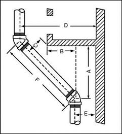
Our formula will involve three symbols. The first symbol will be an A, and it will be representative of the distance from the center of your 45° fitting to bottom edge of the window. The distance from the center of the rising pipe to the outside edge of the window will be known by the letter B. We will use the letter C to indicate the distance from the center of the Travel piece of

GETTING AROUND PROBLEMS

FIGURE 2.7 ■ Pipe offsets around obstructions.

pipe from the edge of the window. Using E to indicate the distance of the center of the rising pipe from the right edge of the window and D to indicate the center of the offset rising pipe from the right edge of the window, we can use the formula. Let’s see how it works.

To find the distance from the bottom of the window to the starting point of the offset, you would take the distance from the center of the riser to the left edge of the window (B) and add the distance from the corner of the left window edge to the center of the pipe (C) times 1.414. The formula would look like this: A = B + C X 1.414. Refer to Fig. 2.7 for an example. Now let’s put measurement numbers into the formula.

Assume that you want to find A. Further assume that B is equal to one foot and that C is equal to six inches. The numerical formula would be like this: A = 12 inches (B) + 6 inches (C) X 1.414 = 12 inches + 8V2 inches = 20V2 inches. This would prove that the upper 45° fitting would be 20V2 inches from the edge of the right edge of the window. As you can see, the actual proce­dure is not as difficult as the intimidation of using formulas might imply.

CUTTING SQUARE WITHOUT A SQUARE

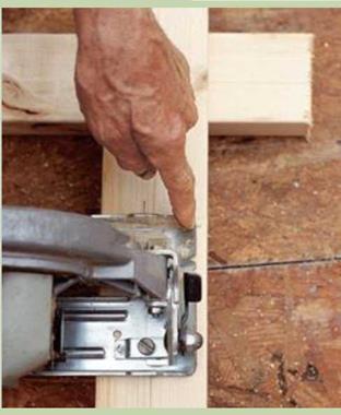
One of the most important skills a carpenter learns over the years is train­ing and trusting his or her eye. And one of the best ways to develop this capability is to cut square by eye. Instead of using a square to mark a 90- degree cutoff line on a board, simply make a quick pencil mark for length on the board, line up a circular saw, and make the cut. Over the course of framing a floor or a wall, this method can save you plenty of time.

If you’re comfortable using a circular saw, it’s not difficult to master this technique. Position the saw with the blade aligned on the cutoff mark and the front of the saw’s base parallel with the edge of the board. As you make the cut, keep the base parallel with the board’s edge. Practice a few times on scrap, check each cut, and adjust the angle of the cut until you’ve got it right. In time, you’ll develop a “feel" for square.

Make square cuts by eye. To make a square cut, put the blade on the cut line and keep the front edge of the saw base parallel with the board.

This is an easy way to spot layout mistakes. Take the time to check the framing against the details shown on the plans. Corrections are much easier to make now than after the floor sheathing is installed. Enjoy the moment. Joists on edge are beautiful in their own right, clearly and unmistakably showing the promise of a new building.

STEP 7 INSTALL EXTRA JOISTS AND BLOCKING

Until recently, extra joists were often required under walls that ran parallel to the joists, because they helped support the roof structure. Most houses built these days use roof trusses, however, which are engineered to span from outside wall to outside wall without the need for interior support. There usually isn’t a need to in­stall extra joists under walls, though some local codes still require them. Check with your town or city building department to make sure.

CUTTING SQUARE WITHOUT A SQUARECUTTING SQUARE WITHOUT A SQUAREПодпись:Similarly, wood or metal bridging is no lon­ger required. Installed in crossed pairs between