FIXTURE-UNIT TABLES

Fixture-unit tables are often used when sizing drains and sewers. The table in Figure 4.1 is an example of a table that expresses the maximum number of fix­ture units allowed on pipes of various sizes and with various amounts of fall. Before we go on, look at the category for 3-inch pipe, at a V4-inch per foot fall. It says that you are allowed 27 drainage fixture units. But, notice the lit­tle number 2 next to the number of fixture units. That number indicates a note or exception. When you look at the bottom of the table, you will see that the note tells you that not more than two water closets can be carried on a 3-inch pipe. There are exceptions, but if you stick with this rule, you can’t go wrong. This is one of the tables that I was telling you about earlier.

Diameter of pipe

Fall in

inches per foot

(in)

‘/ні

%

‘/4

‘/2

2

21

26

2 Vi

24

31

3

202

272

362

4

180

216

250

5

390

480

575

6

700

840

1000

8

1400

1600

1920

2300

10

2500

2900

3500

4200

12

3900

4600

5600

6700

15

7000

8300

10,000

12,000

‘Includes branches of the building drain. The mini­mum size of any building drain serving a water closet shall be 3".

“Not over two water closets.

FIGURE 4.1 ■ Allowable fixture-unit loads. (Courtesy of McGraw-Hill)

FIXTURE-UNIT TABLES

Fixture-unit

value as load Minimum size

factors of trap (ini


Fixture type


Bathroom group consisting of water closet, lavatory, and bathtub or shower

Bathtub (with or without overhead shower) or whirlpool attachments Bidet

Combination sink and tray

Combination sink and tray with food disposal unit

Dental unit or cuspidor

Dental lavatory

Drinking fountain

Dishwashing machine domestic

Floor drains

Kitchen sink, domestic

Kitchen sink, domestic with food waste grinder and/or dishwasher Lavatory Lavatory

Lavatory, barber, beauty parlor

Lavatory, surgeon’s

Laundry tray (1 or 2 compartments)

Shower stall, domestic Showers (group) per head Sinks Surgeon’s

Flushing rim (with valve)

Service (trap standard)

Service (P trap)

Pot, scullery, etc.

Urinal, pedestal, siphon jet, blowout Urinal, wall lip Urinal, washout Washing machines (commercial)

Washing machine (residential)

Wash sink (circular or multiple) each set of faucets Water closet, flushometer tank, public or private Water closet, private installation Water closet, public installation


6

2

lVi

2

Nominal l’A

3

1 Vi

4

Separate traps 1 Vi

1

1%

1

l’A

‘A

1

2

lVi

1

2

2

l’A

3

lVi

1

Small P. O. l’A

2

Large P. O. l’A

2

l’A

2

l’A

2

l’A

2

2

3

3

llA

8

3

3

3

2

2

4

l’A

8

Note 6

4

Note 6

4

Note 6

3

2

2

Nominal 1 Vi

3

Note 6

4

Note 6

6

Note 6


FIGURE 4.2 ■ Fixture-unit ratings. (Courtesy of McGraw-Hill)


The information in Figure 4.2 is representative of what you might find in your local codebook. This is the type of table that assigns specific ratings for fixture units on given fixtures. In cases where a known fixture is not listed, an­other type of table, like the one in Figure 4.3, is used to assign ratings for fix­ture units. Before we get too many tables in front of us, let’s go over the three that you’ve just been introduced to.


The table in Figure 4.1 is easy enough to understand. If you find the size of the pipe you are working with, you can quickly ascertain the number of fix­ture units allowed on the pipe at a given grade. When you know the number of fixture units and the grade of the pipe, you can tell what size pipe is suit­able. For example, a 4-inch sewer that is installed with a grade of one-quarter of an inch per foot can handle up to 216 fixture units, and that’s a lot of drainage. Upgrading to a 6-inch pipe with the same grade will allow you to load the pipe with 840 drainage fixture units. That’s all there is to that table.

Подпись:FIXTURE-UNIT TABLESПодпись: When dealing with a residential property, a 4-inch sewer will handle all of the fixture units that could reasonably be installed in a home. Avoid installing a 3-inch sewer. Give homeowners the option of expansion by spending a little more money for the larger sewer.The listings in Figure 4.2 are compre­hensive and easy to understand. For ex­ample, a residential toilet is assigned a fixture-unit rating of four. A typical lava­tory has a rating of one fixture unit. Do­mestic shower stalls are rated for two fix­ture units. If you add this up, you find that the three normal bathroom fixtures total a rating of seven fixture units. How­ever, if you look at the top of the list, you will see that a bathroom group that con­sists of a toilet, lavatory, and bathtub or

Подпись: been there done that As a young plumber, I believed that the code was the code. At the time, I worked in a metro area where there were numerous jurisdictions. Even being close together, I found out the hard way that not every city and county used the same code. Always check the local code in the area where you will be working to stay out of trouble. shower has a rating of 6 fixture units. Wait a minute, that’s one fixture unit less than the individual ratings for the same fixtures. What gives? In this case, as­suming that all of the fixtures were being placed in the same bathroom, you could use the lower of the two ratings. Why? Because it is assumed that not all of the fixtures will be being used simul­taneously if they are confined to a single room. The use of a table, like the one in Figure 4.2, makes sizing drains a lot easier.

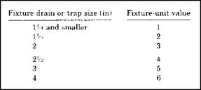
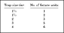
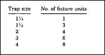
There may be times when the fixture that you are seeking a rating for will not be listed on a fixture-unit table. If this is the case, you can use a table, like the one in Figure 4.3, to assign a rating for fixture units. For example, a fixture with a 2-inch drain that is not otherwise listed would be

FIXTURE-UNIT TABLES

FIGURE 4.3 ■ Allowable fixture units based on trap size. (Courtesy of McGraw-Hill)


Maximum no. of fixture units that may
be connected to:


Diameter

of

pipe"

(in)

Any

horizontal fixture branch14

One stack of 3 stories or 3

intervals

maximum

More than 3 stories in height

Total for stack

Total at one story or branch interval

VA

1

2

2

1

Г/І

3

4

8

2

2

6

10

24

6

2 Vi

12

20

42

9

3

20“

ЗО"

60”

16"

4

160

240

500

90

5

360

540

1100

200

6

620

960

1900

350

8

1400

2200

3600

600

10

2500

3800

5600

1000

12

3900

6000

8400

1500

15

7000

‘Does not include branches of the building drain.

"Not over two water closets.

’Not over six water closets.

4509f less for battery vented fixture branches, no size reduction permitted for battery vented branches throughout the entire branch length.

”The minimum size of any branch or stack serving a water closet shall be


3".


FIGURE 4.4 ■ Maximum fixture units. (Courtesy of McGraw-Hill)


rated for three fixture units. A 4-inch drain would carry a rating of six fixture units. Pretty simple stuff, huh?

Some tables, like the one in Figure 4.4, deal with different piping arrange­ments. For example, the table in Figure 4.4 allows you to rate any horizontal branch stacks for multiple-story buildings and branch intervals. Notice that


Diameter of vent

Number of wet-vented fixtures stacks (in)


1 or 2 bathtubs or showers 2

3 to 5 bathtubs or showers 2Vi

6 to 9 bathtubs or showers 3

10 to 16 bathtubs or showers 4


FIGURE 4.5 ■ Vent sizing table. (Courtesy of McGraw-Hill)


FIXTURE-UNIT TABLES

FIGURE 4.6 ■ Trap-to-vent distances. (Courtesy of McGraw-Hill)

several of the ratings are marked with exclusions. This is the type of detailed information that you must be on the lookout for.

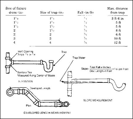
Suppose you are concerned about sizing a vent stack that will accommo­date wet-vented fixtures? No problem, just use a table like the one in Figure 4.5. This table is so simple that it needs no explanation. Now, what if you need to know how long a trap arm may be? Refer to a table like the one in Fig­ure 4.6 for the answers to your questions. Depending on trap size, the size of the fixture drain, and the amount of fall on the trap arm, you can choose a maximum length quickly.

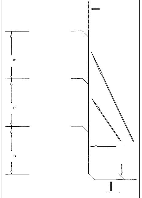
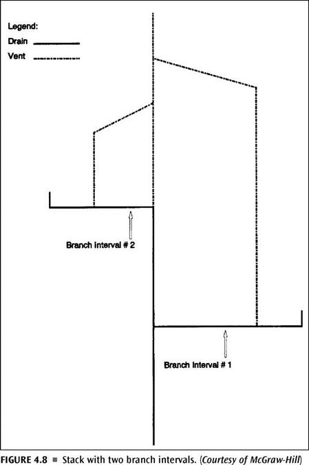
Take a look at Figure 4.7. It is a riser diagram of a branch-interval de­tail. It is sometimes necessary to break a drainage system down into branch intervals for sizing. If you need to do this, you can refer to this drawing for a clear understanding of where branch intervals break and what they are. Figure 4.8 shows a stack with two branch intervals. To size a system like this, you must apply your sizing techniques to each individual branch and to the stack.

Vent Through Roof


3rd Branch Interval


2nd Branch Interval


1st Branch Interval


Soil Stack


Cleanout


Building Drain


FIGURE 4.7 ■ Branch-interval detail. (Courtesy of McGraw-Hill)


FIXTURE-UNIT TABLES

FIXTURE-UNIT TABLES

TRAP SIZING

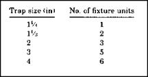
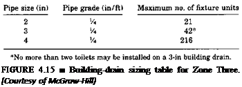
Trap sizing is a simple procedure. All you need is some basic information and a sizing table. If you know your trap size, you can determine the fixture-unit load that is allowable. When you know the number of fixture units that will be placed on a trap, you can decide on a trap size. There’s not much to it. Fig­ures 4.9, 4.10, and 4.11 show limits for fixture units on traps in the three main plumbing codes. If you notice, two of the codes have the same ratings, but one is more liberal than the other two. Remember to use your local code when doing actual sizing.

FIXTURE-UNIT TABLES

FIGURE 4.9 ■ Zone Two’s fixture – unit requirements on trap sizes. (Courtesy of McGraw-Hill)

FIXTURE-UNIT TABLES

FIGURE 4.10 ■ Zone Three’s fixture-unit requirements on trap sizes. (Courtesy of McGraw-Hill)

FIXTURE-UNIT TABLES

FIGURE 4.11 ■ Zone One’s fixture – unit requirements on trap sizes. (Courtesy of McGraw-Hill)

THE RIGHT PITCH

Подпись: ✓ fast code fact Be aware that S-traps are not legal for new installations and drum traps are usually, but not always, illegal. So are crown-vented traps. P-traps are the type most often used. Подпись: ► sensible shortcutПодпись:

Подпись: Pipe diameter (in) FIXTURE-UNIT TABLES Подпись: Having too much grade on a pipe can be as bad as not having enough. If a drain pitches downward too hard, liquids will leave the pipe and suspend solids in the drain that could cause a stoppage. Maintain an even grade, usually one-quarter-of- an-inch per foot. FIXTURE-UNIT TABLES

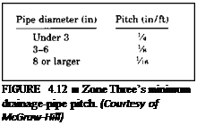
Having the right pitch on a pipe is neces­sary when complying with a plumbing code. The amount of pitch, or grade, on a pipe can affect its allowable length and fixture-unit load. You can use the tables in Figures 4.12, 4.13, and 4.14 as examples of how a local code might put rules in place for you to follow. The tables are easy to understand and use.

Подпись: FIGURE 4.15 ■ Building-drain sizing table for Zone Three. [Courtesy of McGraw-Hill)
SIZING BUILDING DRAINS

Sizing building drains is simple when you have a sizing table and some basic information. Refer to Figure 4.15 for an example of a sizing table for a build­ing drain. In this example, all pipes are based on a pitch of one-quarter of an inch per foot. A 3-inch pipe can carry up to 42 fixture units, but not more than two toilets. Tables like this one should be available in your local codebook.

Contact Filter Paper Techniques

Although far less common than in the laboratory, techniques for in-situ matric suc­tion measurements using the contact filter paper (CFP) method and in-situ total suction measurements using the non-contact filter paper method have also been described (Greacen et al., 1989). The filter paper technique is, in theory, applicable over the entire range of total suction, but the method tends to be impractical for both extremely high and extremely low suction values. Reliable measurements tend to be limited to a range spanning about 0-10 MPa matric suction for the contact filter paper techniques and between 1 to 10 MPa of total suction for the non-contact technique.

The filter paper method is used as an indirect means of measuring soil suction. The advantages of the method include its simplicity, its low cost, and its ability to measure a wide range of suction. Although this technique is more often used in the laboratory, the filter paper method has also been used in the field to measure soil suction. The CFP technique relies on measuring the equilibrium water content of small filter papers in direct contact with unsaturated soil specimens. Figure 3.17 shows the filter paper setup and installation to put it in direct contact with the soil specimen. In the laboratory the filter paper is placed in contact with the soil specimen in an airtight container for seven days and thereafter the water content of the filter paper is determined and the matric suction of the soil specimen is in­ferred from a calibration curve. Filter paper not in contact with the specimen permits water exchange only in the vapour phase and therefore measures the total suction (Rahardjo & Leong, 2006).

The water content of the filter paper at equilibrium is measured gravimetrically and related to matric soil suction through a predetermined calibration curve for the particular type of paper used. Commonly used types of papers include Whatman No. 42 and Schleicher and Schuell No. 589. Calibration and test procedures for the measurement of matric suction using the contact filter paper technique are described in the ASTM Standard D5298-94 (1997). However, different researchers have sug­gested different calibration curves for the same filter paper (Leong et al., 2002; Rahardjo and Leong, 2006).

Contact Filter Paper Techniques

Fig. 3.17 Contact filter paper setup procedure (in laboratory). Reproduced with permission of R. Bulut

3.2 Conclusions

A considerable variety of test and assessment procedures are available for measuring the volumetric and gravimetric water contents of both laboratory and in-situ road construction and geotechnical materials. The simplest tests to perform are usually destructive, but sophisticated geo-physical techniques are becoming increasingly common and usable, not only as identification tools, but also as quantitative mea­surement techniques.

Suction, which has such a large effect on the mechanical properties of soils and aggregates, is probably the quantity most difficult to measure successfully and must usually be monitored indirectly by the response of, e. g., water content and vapour monitoring. As the relationships between these secondary responses and the primary cause, suction, may both be imprecisely described and hysteretic there is usually some uncertainty in value of suction determined.

Permeability, another major quantity that needs evaluating, is more readily mea­sured using flow tests, but difficulties arise when measuring coarse-grained materi­als, such as road aggregates. Producing samples that are representative with respect to density and grading can be a challenge and the devices available for testing can allow water to preferentially flow along the edges, introducing further uncertainties into the assessment.

Nevertheless, a knowledge of permeability, suction and water content is indis­pensable for effective design and assessment of the movement of water in the high­way and its adjacent environment.

Extreme-value distributions

Hydrosystems engineering reliability analysis often focuses on the statisti­cal characteristics of extreme events. For example, the design of flood-control structures may be concerned with the distribution of the largest events over the recorded period. On the other hand, the establishment of a drought- management plan or water-quality management scheme might be interested in the statistical properties of minimum flow over a specified period. Statistics of extremes are concerned with the statistical characteristics of Xmax, n = max{X1, X2,…, Xn} and/or Xmjn,„ = min{X1, X2,…, Xn} in which X1, X2,…, Xn are observations of random processes. In fact, the exact distributions of extremes are functions of the underlying (or parent) distribution that generates the ran­dom observations X1, X2,…, Xn and the number of observations. Of practi­cal interest are the asymptotic distributions of extremes. Asymptotic distribu­tion means that the resulting distribution is the limiting form of Fmax, n(y) or Fmin, n(y) as the number of observations n approaches infinity. The asymptotic distributions of extremes turn out to be independent of the sample size n and the underlying distribution for random observations. That is,

limn^x Fmax, n( y) = Fmax( y) limnxx Fmin, n( y) = Fmin( y)

Furthermore, these asymptotic distributions of the extremes largely depend on the tail behavior of the parent distribution in either direction toward the extremes. The center portion of the parent distribution has little significance for defining the asymptotic distributions of extremes. The work on statistics of extremes was pioneered by Fisher and Tippett (1928) and later was extended

by Gnedenko (1943). Gumbel (1958), who dealt with various useful applications of Xmax, n and Xmin, n and other related issues.

Three types of asymptotic distributions of extremes are derived based on the different characteristics of the underlying distribution (Haan, 1977):

Type I. Parent distributions are unbounded in the direction of extremes, and all statistical moments exist. Examples of this type of parent distribution are normal (for both largest and smallest extremes), lognormal, and gamma distributions (for the largest extreme).

Type II. Parent distributions are unbounded in the direction of extremes, but all moments do not exist. One such distribution is the Cauchy distribution (Sec. 2.6.5). Thus the type II extremal distribution has few applications in practical engineering analysis.

Type III. Parent distributions are bounded in the direction of the desired extreme. Examples of this type of underlying distribution are the beta dis­tribution (for both largest and smallest extremes) and the lognormal and gamma distributions (for the smallest extreme).

Owing to the fact that Xmin, n = – max{-X1, -X2,…, – Xn}, the asymptotic distribution functions of Xmax, n and Xmin n satisfy the following relation (Leadbetter et al., 1983):

Fmin(У) = 1 – Fmax(-y) (2.84)

Consequently, the asymptotic distribution of Xmin can be obtained directly from that of Xmax. Three types of asymptotic distributions of the extremes are listed in Table 2.3.

Extreme-value type I distribution. This is sometimes referred to as the Gumbel distribution, Fisher-Tippett distribution, and double exponential distribution. The CDF and PDF of the extreme-value type I (EV1) distribution have, respec­tively, the following forms:

x – f

~T~


FeV1( x | f, в) = exp ^ – exp


for maxima


(2.85a)


x – f

~T~


for minima


= 1 – exp – exp


+


Extreme-value distributions

TABLE 2.3 Three Types of Asymptotic Cumulative Distribution Functions (CDFs) of Extremes

Type

Maxima

Range

Minima

Range

I

exp(-e-y)

-го < y < ro

1 – exp(-ey)

-ro < y < ro

II

exp( – ya)

a < 0, y > 0

1 – exp[ ( y)a]

a < 0, y < 0

III

exp[ ( y )a ]

a > 0, y < 0

1 – exp( – ya)

a > 0, y > 0

Extreme-value distributions Подпись: for maxima (2.85b) for minima

y

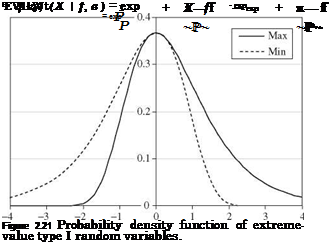
for —to < x, f < to, and P > 0. The shapes of the EV1 distribution are shown in Fig. 2.21, in which transformed random variable Y = (X — f )/p is used. As can be seen, the PDF associated with the largest extreme is a mirror image of the smallest extreme with respect to the vertical line passing through the common mode, which happens to be the parameter f. The first three product-moments of an EV1 random variable are

Px = A1 = f + °.5772p

for the largest extreme

= f — 0.5772P

for the smallest extreme

(2.86a)

= 1.645P2

for both types

(2.86b)

Kx = 1.13955

for the largest extreme

= -1.13955

for the smallest extreme

(2.86c)

The second – to fourth-order L-moments of the EV1 distribution for maxima are A2 = P ln(2) T3 = 0.1699 T4 = 0.1504 (2.87)

Using the transformed variable Y = (X — f )/p, the CDFs of the EV1 for the maxima and minima are shown in Table 2.3. Shen and Bryson (1979) showed

Подпись: XT 1 Подпись: rln( T1) _ln( T 2) Подпись: XT 2 Подпись: (2.88)

that if a random variable had an EV1 distribution, the following relationship is satisfied when f is small:

where xT is the quantile corresponding to the exceedance probability of 1/T.

Example 2.19 Repeat Example 2.17 by assuming that the annual maximum flood follows the EV1 distribution.

Solution Based on the values of a mean of 6000 ft3/s and standard deviation of 4000 ft3/s, the values of distributional parameters f and в can be determined as follows. For maxima, в is computed from Eq. (2.86b) as

Подпись: 4000 1.2826 Подпись: 3118.72 ft3/sв =

V1.645

and from Eq. (2.86a), one has

f = nQ – 0.577в = 6000 – 0.577(3118.72) = 4200.50 ft3/s

Подпись: P (Q > 10, 000) Extreme-value distributions

(a) The probability of exceeding 10,000 ft3/s, according to Eq. (2.85a), is

= 1 – exp[- exp(-1.860)]

= 1 – 0.8558 = 0.1442

(b) On the other hand, the magnitude of the 100-year flood event can be calculated as

У100 = g10° – f = – ln[- ln(1 – 0.01)] = 4.60

в

Hence q100 = 4200.50 + 4.60(3118.7) = 18,550 ft3/s.

Подпись: f W(x | f, а, в) Подпись: а в Подпись: x - f Подпись: a-1 exp Extreme-value distributions Подпись: a- Подпись: for x > f and а, в > 0 (2.89)

Extreme-value type III distribution. For the extreme-value type III (EV3) distri­bution, the corresponding parent distributions are bounded in the direction of the desired extreme (see Table 2.3). For many hydrologic and hydraulic ran­dom variables, the lower bound is zero, and the upper bound is infinity. For this reason, the EV3 distribution for the maxima has limited applications. On the other hand, the EV3 distribution of the minima is used widely for modeling the smallest extremes, such as drought or low-flow condition. The EV3 distri­bution for the minima is also known as the Weibull distribution, having a PDF defined as

Подпись: FW(x | f, a, в) = 1 - exp Extreme-value distributions Подпись: a Подпись: (2.90)

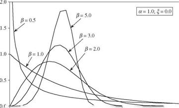
When f = 0 and a = 1, the Weibull distribution reduces to the exponential dis­tribution. Figure 2.22 shows that the versatility of the Weibull distribution function depends on the parameter values. The CDF of Weibull random vari­ables can be derived as

Extreme-value distributions Подпись: (2.91a) (2.91b)

The mean and variance of a Weibull random variable can be derived as

Подпись: (2.92)І2 = в (1 – 2-1/a) Г 1 + 1

Generalized extreme-value distribution. The generalized extreme-value (GEV) distribution provides an expression that encompasses all three types of extreme – value distributions. The CDF of a random variable corresponding to the maxi­mum with a GEV distribution is

Extreme-value distributions

Extreme-value distributions

Fgev(x | f, a, в) = exp


for a = 0


(2.93)


Extreme-value distributions

I “————— 1————————– 1————————– f———————————————– і

0.0 0.5 1.0 1.5 2.0 2.5 3.0

x

Figure 2.22 Probability density functions of a Weibull random variable.


When a = 0, Eq. (2.93) reduces to Eq. (2.85a) for the Gumbel distribution. For a < 0, it corresponds to the EV2 distribution having a lower bound x > % + в/а, whereas, on the other hand, for a > 0, it corresponds to the EV3 distribution having an upper bound x < % + в/а. For |a| < 0.3, the shape of the GEV distribution is similar to the Gumbel distribution, except that the right-hand tail is thicker for a < 0 and thinner for a > 0 (Stedinger et al., 1993).

Extreme-value distributions Подпись: (2.94a) (2.94b) (2.94c)

The first three moments of the GEV distribution, respectively, are

where sign(a) is +1 or -1 depending on the sign of a. From Eqs. (2.94b) and (2.94c) one realizes that the variance of the GEV distribution exists when a > -0.5, and the skewness coefficient exists when a > -0.33. The GEV distri­bution recently has been used frequently in modeling the random mechanism of hydrologic extremes, such as precipitation and floods.

Extreme-value distributions Подпись: 6(2-a) Подпись: (2.95a) (2.95b) (2.95c)

The relationships between the L-moments and GEV model parameters are

. FROM PLANS TO PLATES

Подпись:—4-

Chalklines are snapped on the floor to show the location of all the walls. The top and botzom plates will be tacked to the deck along those lines.

. FROM PLANS TO PLATES

plates temporarily tacked together on the sub – floor, you can mark up the plates to identify exactly where each stud, king stud, header, and trimmer is located. If you haven’t already done so, take the time to familiarize yourself with the various parts that go into a wood-frame wall (see the illustration on p. 84).

Mark wall layouts

Three marking tools are essential: a chalkline, keel, and a carpenter’s pencil. A chalkline and an ample supply of chalk allow you to snap exterior and interior wall layout lines on the

4

sublloor or slab (see the photo on p. 78). It’s not necessary to mark two lines for a wall; instead, use a carpenter’s crayon, or keel, to mark an “X" on the side of the line that will be

LAYOUT STARTS WITH SNAPPED LINES.

. FROM PLANS TO PLATESThe floor deck is clear, but not for long. Snapped chalklines identify where the walls will be located.
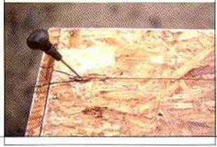
Подпись: Helping HandПодпись: An awl helps during solo layout. When working alone to mark measurements on wood floors, use an awl to hold the chalkline or measuring tape in place. If you don't have an awl, a nail will do.. FROM PLANS TO PLATES

covered by the wall plates. Keel is also useful for labeling parts, writing cripple sizes on headers, and indicating door and window – openings.

To make a snapped line easier to find, use a pencil or keel to make a crow s foot, or a large “V” mark, with the point centered on the line. If you snap a line in error, wipe it away with your foot or at least draw a wavy line through it before snapping a line in the correct place. Use a carpenter’s pencil to make stud layout lines on the plates. Try to keep all markings clear and simple, and avoid complicating things unnecessarily. The object is to get all the information you need off the plan and onto the floor in an understandable format.

PNEUMATIC NAILERS

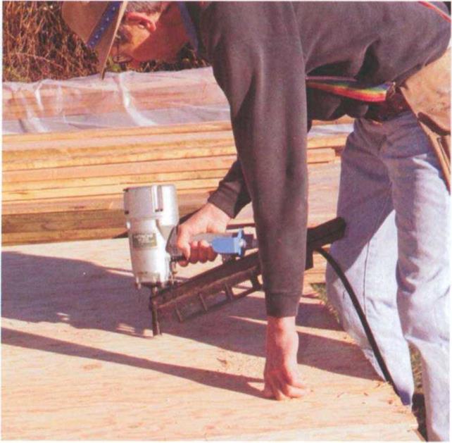
My first pneumatic tool drove only sta­ples, and I used it to nail subfloor and roof sheathing. Today, pneumatic nailers drive many types of fastener. In some areas of the country, they are almost as common on job sites as hammers.

What makes a pneumatic nailer so appealing is its speed. The nails are automatically fed into the nailer from a clip or coil (which can hold 200 nails or more), so you don’t have to keep reach­ing into your tool belt for nails.

Today, there’s a nailer for every job, from rough framing to roofing to the finest finish work. I own two framing nailers, a finish nailer, and a palm nailer. Both framing nailers drive 8d or 16d nails (see the photo below)—one feeds the nails from a clip, and the other feeds them from a coil. Both fit well in my hand,

PNEUMATIC NAILERS

A framing nailer can be used for rough framing, as well as for nailing a ply­wood subfloor to joists. (Photo by Roe A. Osborn.)


PNEUMATIC NAILERS

A finish nailer works well for trimwork, such as nailing in the stool for a win­dow. (Photo by Roe A. Osborn.)


seldom jam, and require very little main­tenance. They take a drop of oil twice a day and need to be cleaned with a wire brush now and then, but that’s about it.

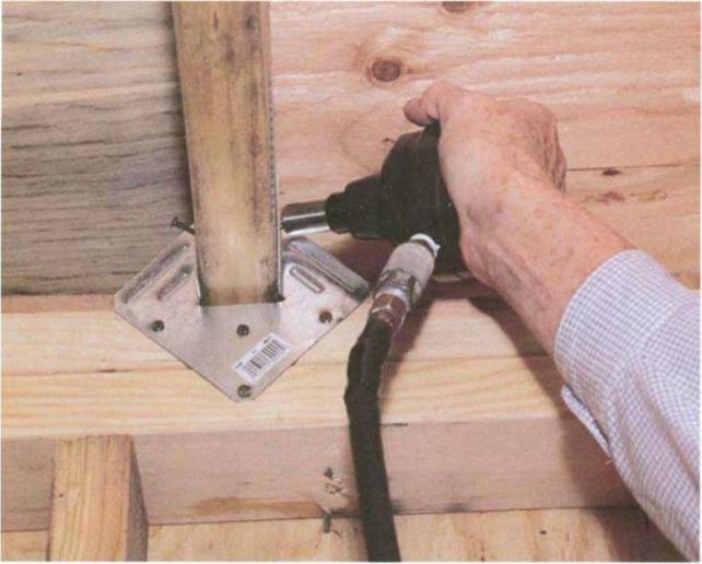
The same is true with my finish nailer, which drives nails from 1 in. (brads) to 2У2 in. (8d) long (see the photo above). Finish nailers not only drive the nails but can also set them below the surface of the wood, which saves a lot of nail­setting time. I use my palm nailer to drive nails in hard-to-get-at places, where it’s not easy to swing a hammer. It’s a
great tool for nailing in hurricane ties and joist hangers (see the photo on p. 56).

Most nailers operate off compressed air, though there are also electrically pow­ered brad nailers and staplers and propane-powered framing and finish nailers. Buying a nailer and the necessary air compressor, gauges, and air hoses represents a substantial investment, though these items can pay for them­selves in short order due to increased productivity.

Pneumatic-nailer safety

• A pneumatic nailer is as dangerous as a gun and needs to be treated with respect.

• Read and carefully follow the instruction manual regarding maintenance and use.

• Don’t point a nailer at yourself or at others.

• Don’t walk around with your finger on the trigger. You might bump the nailer against your leg, release the safety, and fire a nail accidentally.

• Adjust the air pressure as needed (larger nails re­quire more pressure). But don’t exceed the recom­mended amount of air pressure.

• Wear safety glasses or goggles.

• Don’t nail with the gun in front of your face, espe­cially if you are working on a vertical surface. If you hit a hard knot or metal strap, the gun can bounce back and strike you.

• Disconnect the gun from the air compressor when clearing a jammed nail.

• When nailing studs to a plate, drive the low nail first. Then remove the hand holding the stud and drive the high nail. If you drive the high nail first, sooner or later you will miss the wood plate and drive a nail through your hand.

• Take a break now and then to stay focused. An unfocused mind can cause you to shoot a nail into your body, which will bring you back to reality like an early morning alarm clock, sudden and unpleasant.

PNEUMATIC NAILERS

A palm nailer can drive nails in tight places, as when installing a joist hanger. (Photo by Roe A. Osborn.)


DRAIN-AND-SEWER CALCULATIONS

D

oing calculations for drains and sewers is similar, in principle, to what you will use for vents in the next chapter. The process involves fixture units, the developed length of piping, sizing tables, and so forth. Pay­ing attention to details is an important element in designing any type of sys­tem, and this certainly holds true when sizing drains and sewers. Moving too quickly and using the wrong sizing table can cause you a lot of trouble. When work is simplified, it sometimes seems so simple that it is taken too lightly. Don’t make mistakes by not paying attention to footnotes and exclusions when you use sizing tables. If you read the tables carefully and apply them properly, sizing is not difficult.

Подпись:Some plumbers get so accustomed to using sizing tables that they fail to think of code requirements that may make the tables inaccurate if all notes are not observed and followed. For example, let’s say that you are sizing a sewer for a home.

You might do your homework and find that the total number of fixture units is low enough that a 3-inch sewer can be used. This might be the case, but you could be setting yourself up for trouble.

Accuracy in sizing pipes is essential to a job in more than one way. First, you have to draw riser diagrams and size the pipes for code approval. And, you need accurate sizing to price a job for bidding purposes.

Let’s say that you did believe that a home could get by with a 3-inch sewer. Assume that the home was a town­house and that it was one of 300 in a project, where you were bidding the en­tire project. This means that you basically figure maybe four styles of houses

49

and then apply the information to the entire project. The cost difference between 3-inch and 4-inch pipe doesn’t seem like a lot when you are dealing with short runs. But, when you are dealing with 300 runs, even small differ­ences in cost can add up quickly. So, what would happen if you figured a job for 3-inch sewers and wound up having to install 4-inch sewers? You or your employer would lose money, possibly a substantial sum.

Подпись: ► sensible shortcutDRAIN-AND-SEWER CALCULATIONSПодпись: As a rule-of-thumb, don’t plan on putting more than two toilets on a 3-inch drain. There are often conditions that will allow up to three toilets on a 3-inch drain, but I would suggest running a 4-inch pipe for three toilets if you want to keep it simple.When we get further into this chap­ter you will see actual examples of how a mistake might be made when using siz­ing tables for drains and sewers. But, I’d like to point out a quick one now, so that you will keep your eyes open when we get to the sizing tables. okay, it is very likely that the total fixture load for a 3- bathroom townhouse would be low enough to allow the use of a 3-inch sewer. if you were in a hurry, did a quick calculation of fixture units and scanned a sizing table, you might jump right at using 3-inch pipe to keep costs down. This would be a mistake. Why? Be­cause even though a 3-inch pipe could handle the fixture units, most codes limit a 3-inch pipe to serving no more than two water closets in close prox­imity. If the townhouse has three toilets, a 4-inch sewer is likely to be needed.

As a teacher of plumbing courses, I’ve seen a number of experienced plumbers fall for this trap on some of the tests that I’ve created. The plumbers get into a rhythm and fail to think or to see the notes on the sizing charts and distance requirements. It’s bad to miss a question on an exam, but it would be much worse to make the mistake in the real world of plumbing. By catching the plumbers in the classroom, I hope to make them aware of the crossover traps that can be embedded in the plumbing code. There are usually excep­tions, options, and exclusions that can change the meaning of the code in cer­tain situations. The 3-inch sewer is one excellent example of such pitfalls. You do have to pay attention to what you are doing when sizing systems.

TYPES OF SANITARY DRAINS

There are several types of sanitary drains. A building sewer is usually consid­ered to be the main drain for a building that starts outside of the building and

Подпись:extends to a municipal sewer or private sewage-disposal system. Building drains are the primary drains inside of a building. Then there are branch intervals, horizon­tal branches, vertical stacks, and so forth. When you begin sizing a drainage system, you must make sure that you are using the proper sizing procedures for the type of drain or sewer that you are working with.

All types of drains and sewers can be calculated with a method that depends on the ratings of drainage fixture units.

DRAIN-AND-SEWER CALCULATIONSПодпись: ► sensible shortcutПодпись: Use the tables in your codebook to calculate fixture units, load ratings, and pipe sizing. This is fast, easy, and accurate.Fixture-unit ratings are established by lo­cal codes. A probability factor is built into the system. While a direct flow rate or discharge rate cannot be determined from the rating of fixture units, the fix­ture units are accurate enough to allow a sensible system to be designed in compliance with the plumbing code.

On the river to Nubia, navigation works on the Nile (IIIrd and IInd millennia BC)

Navigation canal at the first cataract

Nubia is rich in quarries, and in gold and amethyst mines. A concerted effort to exploit these resources of the south began in the VIIth Dynasty, under the ancient Empire. But the Aswan rapids, comprising the first cataract of the Nile (Figure 3.4), present an obsta­cle to navigation. In about 2400 BC the Pharaoh Merenre I has his close lieutenant Ouni build a flume system to allow boat passage through this obstacle. Ouni, who later becomes governor of Upper Egypt, had his autobiography engraved in his tomb, where one can read the following:

“Then His Majesty sent me to dig five canals (flumes?) in Upper Egypt and to construct three

barges and four transport boats, from acacia wood of the land of Ouaouat. The chiefs of the

lands of Ouaouat, Iam and Medla had the wood cut for this. I accomplished all of my task in

a single year. When the boats were launched, they were also loaded with big wide blocks of

1 3

granite for the pyramid (of Merenre)"

This account tells us the main reason for Ouni’s mission: the descent of boats com – [98]
ing from the stone quarries. The current in the flumes was surely too strong for upstream passage. The flumes were rebuilt, or enlarged, under the reign of the Pharaoh Sesostris III (XIIth Dynasty) in about 1870 BC, height of the middle Empire. But now the rea­sons were clearly military, since the work enabled Egyptian expeditions to travel upstream to the second cataract (in years 8, 12, 16 and 19 of the reign).[99] But clearly these flumes either were undersized or filled with sand, which would be no surprise given the strength of the currents in this area and therefore the sand load carried by the flow. New work was conducted under Thoutmosis I and Thoutmosis III, between 1490 and 1425 BC, this time including the construction of a true canal 10 m wide and 7 m deep.[100]

On the river to Nubia, navigation works on the Nile (IIIrd and IInd millennia BC)Herodotus did not travel upstream of the first cataract during his voyage in Egypt. Here is how the navigation conditions in this zone were described to him:
“From the city of Elephantine, going upcountry, the land is steep. There travelers must bind the boat on both sides, as one harnesses an ox, and so go on their way. If the rope were to break, the boat would be borne to its destruction by the strength of the current. This part of the country is four days’ journey by boat, and the Nile here is as twisting as the Maeander; there is a length of twelve schoeni to pass through in this fashion.”[101]

Strabo’s much later account of his trip up the Nile (by land route) beyond the cataract does not mention these works, indicating that the canal was no longer in serv­ice. It is not hard to imagine that it was quite difficult to permanently maintain such a project, without locks, in an area of strong currents.

Figure 3.4 Rough terrain at the site of the first cataract, upstream of Aswan, at low water (photo by the author)

Suction Plate

A simple laboratory variant of the tensiometer method for measuring matric suction of fine-grained soils uses a semi-pervious sintered glass plate. A small soil sample

Suction Plate

Fig. 3.15 Comparison between laboratory soil suction measurements with tensiometers and TCS. Reproduced with permission of D. Fredlund

is placed on the glass plate and covered immediately with a cap so that the vapour pressure around the soil comes to equilibrium with the suction in the soil, preventing drying. On the other side of the plate de-aired water is provided in a small chamber. The soil attempts to suck water across the glass plate from the chamber but the only way this can happen is by water being drawn into the chamber via a narrow-bore tube. In the tube, beyond the water, there is a small length of mercury and beyond that, air and a small hand-operated suction pump and vacuum gauge (Fig. 3.16). As the water (and, hence, the mercury) is pulled towards the soil, the operator applies a partial vacuum to oppose this and to keep the mercury in the same po­sition. Once the operator no longer needs to apply additional suction, the suction in the soil specimen and applied by the operator are in equilibrium and the suc­tion value may be read from the gauge. Typically, readings may be obtained in around 15 min (though this depends a lot on the soil type). The device is limited to measuring in the range from atmospheric pressure to approximately 70 kPa of suction.

Suction Plate

Part iii: Shape of Particles of the Coarse Aggregate Fraction

The shape of the aggregate particles, from flat and elongated to cubical ones, exer­cises a certain influence on the SMA mixture. A high content of flat and elongated particles has the following effects:

• Increases the content of air voids in a compacted mixture of coarse (active) aggregates

• Decreases the workability of a mixture

• Increases the risk of fat spots appearing when compacting the SMA course

In the German DAV handbook (Druschner and Schafer, 2000), attention has been paid to the impact of the shape of particles from the fraction 2/5.6 mm on the content of voids in SMA, especially with reference to the SMA mixtures 0/8 and 0/8S.

Step 10-Install Nail-Flange Windows

Before Wall is Stood Up

a. Check plans for correct window.

b. Check window opening for protrusions (nails, wood splinters, etc.) that might hold window away from edge.

c. Install window flashing. (See “Window Flashing Installation," Chapter 6.)

d. Set window in opening, making sure window is right side up.

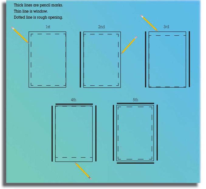
e. Slide window to each end of opening, and draw a line on the sheathing or flashing with a pencil along the edge of window. (Draw lines before caulking window.)

f. Center window in marks you have just drawn.

g. Nail window sides and bottoms, using appropriate nails.

h. Do not nail top of window.

Step 10-Install Nail-Flange Windows

11: Stand wall.

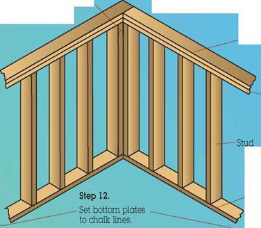
12: Set bottom plate. 13: Set double plate. 14: Set reveal.

Step 10-Install Nail-Flange Windows
Step 10-Install Nail-Flange Windows15: Nail wall.

Подпись: The reveal is the amount of space on the corner stud of a wall after another wall is joined to it.Подпись:Подпись: Double plateПодпись: Step 15. Nail walls together, and nail bottom plate. Подпись:Подпись: Bottom plateStep 10-Install Nail-Flange Windows

Nail the end stud to set the reveal* in the middle of the wall where the two walls join. The reveal in the middle of the wall should be the same as the top and bottom reveal.

Step 13.

Set double plate.

Make sure top plates are down tight to studs.