Basic Principles of Heat Transfer

The basic principles to model the complete time-dependent heat transfer in soils are described in this section. More details of these and the associated effects can be

found in some of the better or more specialist geotechnical textbooks, for example Mitchell and Soga (2005) or Fredlund and Rahardjo (1993).

The water content in various road structures and the underlying soil are subject to climatic (temperature) effects. An example of the thermal variation in a road structure is given in Fig. 4.1. It can be clearly seen that the thermal state is definitely changing, which means that it is characterised by the heat transfer properties of the material. Temperatures may be positive or negative (inducing freezing). Heat trans­fer in soils is due to conduction, radiation, convection and vapour diffusion. A gen­eral overview of thermal transfer may be found in many textbooks, e. g. Selvadurai (2000) or Lewis and Schrefler (1998).

As pavement surface temperature depends greatly on the weather, typically changing hourly and daily, the physical process never reaches a steady state (i. e. there would be only a long-term equilibrium).

Geostructures, like road pavements and embankments, are made up of porous materials with solid and fluid phases. At micro-scale, i. e. the grains and pores scale, the heat transfer is highly complex, involving convection and radiation in the pores

Подпись: о о О) З ■4—1 ГО 0) о. Е О) Подпись:Подпись: DateПодпись:Basic Principles of Heat Transfer25

20

15

10

-10

-15

-20

25

20

15

10

5

0

-5

-10

-15

and conduction in the grains. At the engineering scale (i. e. at macro-scale, at the layers thickness scale), the solid, liquid and gas phases may be considered separately as a continuum.

As discussed by Selvadurai (2000), it is known by experience that heat flows from points of higher temperature to points of lower temperature. Heat is, therefore, a form of energy, which is released by warmer regions of a body to the cooler regions.

Although heat flow cannot be measured directly, its presence manifests itself in terms of a measurable scalar quantity, which is the temperature. From the knowledge of the temperature distribution T(x, t) within a region, it is possible to calculate the heat flow within the region. As a consequence, the major part of the study of heat transfer in geostructures focuses on the determination of the temperature distribution within the medium which is subjected to appropriate boundary conditions and initial conditions applicable to T (x, t).

4.2.1 Conduction

Conduction refers to the mode of heat transfer where this energy transport takes place in the solid phase of the porous media and fluids, which are at rest. This is in contrast to convective heat transfer, which involves motion of a conducting fluid.

The grains of a soil, typically, are in contact with each other at distinct contact points and pores between grains are filled with a mixture of air and water. When completely dry the heat flow passes mainly through the grains, but has to bridge the air-filled gaps around the contact points. At very low water contents, thin adsorbed water layers cover the grains. The thickness of these layers increases with increasing water content as introduced in Chapter 2. At higher water contents, rings of liquid water form around the contact points between the grains. From this point on, the thermal conductivity increases rapidly with increasing water content. At even higher water contents, complete pores are filled with water resulting in a further but slower increase in thermal conductivity.

For a conducting medium which possesses homogeneity and isotropy with re­spect to its heat conduction characteristics (all parameters which govern the heat conduction process are assumed to be independent of direction and position), it is assumed that the amount of heat crossing an element of material in a given time, At, is proportional to the difference in temperature, T, and related to the material properties. Generalizing this concept leads to Fourier’s equation that defines a vector of heat flow Q (W/m2):

Q = – XV T = – XgradT (4.1)

where X(W/m°C) is defined as the thermal conductivity of the medium (see Section 4.3). Normally, the thermal conductivity of grains is in the range of 1-3 W/m°C. Water has a thermal conductivity of about 0.6 W/m°C at room tem­perature. In comparison with solids and liquids, the thermal conductivity of air is very small, being about 0.025 W/m°C.

For anisotropic materials like soils, Eq. 4.1 is generalized in matrix form:

Подпись: (4.2)Q = – A. V T = – XgradT

where X is the matrix of thermal conductivities.

Installing Hardware

Specifics vary, but most locksets come with paper templates that locate the center of the holes drilled in the face of the door (face bores) for handle spindles or cylinders and holes drilled into the edge of the door (edge bores) for latch assemblies. A second paper template locates holes drilled in the latch jamb of the door frame. Although the directions given in this section are typical, follow the directions supplied by your lock maker. Note: Measure the door thickness before buying locksets or key cylinders; some mechanisms are adjustable; others fit only specific door thicknesses.

Mortise Lockset

Mortise locksets combine security and convenience, because you can use a single key to operate both a latch bolt and a dead bolt.

Подпись:Подпись:MORTISE LOCKSETS

Mortise locksets house latch bolts and dead bolts in a single casing and can be operated with a sin­gle key turn. Mortising a lock case into the edge of the door takes some work, but the unit is very secure. The door stile must be solid wood for this type of lock.

1. Using the template, mark the edge of the door to indicate the outline of the lock case. Then mark a line running exactly in the center of the edge. Along this centered line, use a 18-in. spade bit to drill holes to the depth of the lock case. Overlap holes slightly to minimize the need for chiseling.

2. Use a chisel to square up the edges of the lock-case mortise. As you chisel, test-fit the lock case periodically to avoid chiseling away any more than necessary. When the lock case fits all the way into the hole, trace the outline of the main latch plate onto the edge of the door. Use a router to mortise the latch plate. Note: If the door edge is beveled, adjust the tilt of the latch plate to match the bevel beforehand.

3. Remove the lock case. Again, using the template, mark knob/spindle and key/cylinder holes on the face of the door stile. Use a hole saw to cut the cylinder hole and a Forstner bit or spade bit to cut the smaller spindle hole, holding drill bits perpendicular to the stile. Drill the holes

image221

Use a chisel to square up the rounded corners of the latch-plate mortise.

image222

Drill the face bores, which were positioned by using a paper template. Use a hole saw for the larger, key/cylinder hole and a Forstner bit for the spindle or thumb-lever hole. The small round level taped to top of drill helps the installer drill perpendicular to the door face.

image223

Properly installed, the holes in the lock case will align with the holes drilled into the door face. If they don’t line up, use a rat-tail file to gradually enlarge the face bores.

until the point of the bit just starts through the other side. To prevent splintering of the stile face, back the drill out and finish drilling from the other side.

4. Reinsert the lock case and screw it to the edge of the door. Then insert the spindles, slide the escutcheons over the spindles, attach the handles or knobs to the spindles, and see if they turn freely. Once they do, screw on all the trim hardware. Typically, door handles or thumb levers are 34 in. to 38 in. high.

Подпись: Strike plates are closely matched to the locksets they're supplied with. Typically, the larger opening receives the dead bolt. For added strength and security, use 3-in. screws that will reach framing. I Reinforced Strike-Plate Assembly

image225

Because 3-in. screws anchor this assembly to framing behind the door frame, this strike plate can’t be dislodged by a kick.

5. Подпись: oltsYou will also find a strike-plate template. The plate is often mortised into the latch jamb about 1 in. below the top of the latch plate; use a router to mortise the strike plate into the jamb. To more accurately position the leading edge of the strike plate, rub pencil lead on the latch edge; when the latch is released against the jamb, it will leave a pencil mark. For greater security, buy a unit with a strike-plate reinforcer and 3-in. mounting screws.

Part iv: impact of the Grains’ Density

The appearance of significant differences in density among individual fractions of the aggregate mix compels us to discuss volume relations in the aggregate mix and necessary adjustments to the binder content

Substantial differences in the densities of aggregates combined in an SMA can cause numerous problems. This situation happens rather seldom; however, it is pos­sible to find very light material combined with very heavy aggregate (e. g., densities of approximately 2.400 and 3.100 Mg/m3, respectively). When designing a particular mix, results of the sieve analysis of constituent aggregates, as well as the overall gradation curve of a mix, indicate the gradation sieve distribution in mass units. In fact, mass and volume distributions do not correspond with each other if there are substantial differences in the densities of aggregates. Hence, guidelines have been created to regulate the allowable difference between densities. For example, a differ­ence of approximately 0.2 Mg/m3 is allowed according to AASHTO M 325-08; if it is higher, the sieve distribution should be converted into volume units. Conducting the sieve analysis and determining the results in volume units have not always been practiced outside the United States

Besides problems with the aggregate mix, the use of aggregates with differ­ent densities brings about the necessity of correcting the binder content. For that purpose, correction coefficients have been used all over the world. Approximate, or “framework,” binder contents in SMAs have been detailed in various reference documents (e. g., standards, guidelines, recommendations) from many countries. The given minimum quantities of binder have been established based on a reference den­sity of an aggregate mix.

For example, in the NAPA SMA guidelines QIS-122 the minimum content of binder in SMA amounts to 6.0% (m/m), but that is the value for a reference aggregate density equal to 2.750 Mg/m3. If the aggregate mixture density is different from the reference one, an adjustment should be made according to the following principles:

• 0.1% of the binder for each 0.05 Mg/m3 of difference between the density of an aggregate mix and the reference density (2.75) could be added or subtracted.

• For a density smaller than 2.75 Mg/m3, the correction bears the plus sign (+); for a density larger than 2.75 Mg/m3, it bears the minus sign (-).

Since 2006 the rules for correcting binder contents have been standardized in European member states of the CEN. The correction coefficient a for aggregate mixes with densities different than 2.650 Mg/m3 has been adopted in the European standard EN 13108-5 on SMA. The minimum content of binder stipulated by the requirements of this standard should be adjusted depending on a calculated as follows:

2.650 a =

Pa

where:

• a = The coefficient adjusting the binder content

• pa = The density of the aggregate mix determined according to EN 1097-6

For a thorough description of the requirements of the EN 13108-5 standard, see Chapter 14.

Beta distributions

The beta distribution is used for describing random variables having both lower and upper bounds. Random variables in hydrosystems that are bounded on both limits include reservoir storage and groundwater table for unconfined aquifers.

The nonstandard beta PDF is

Подпись: 1

Подпись: f NB(x | a, b, a, в) = ■WI. —j—r(x – a)a 1(b – x)e 1 for a < x < b B(a, в)(b – a)a+e-1 “ “

(2.96)

Подпись: Г(д)Г(в) na + в) Подпись: B(a, в) = Подпись: (2.97)

in which a and b are the lower and upper bounds of the beta random variable, respectively; a > 0, в > 0; and B(a, в) is a beta function defined as

Using the new variable Y = (X — a)/(b — a), the nonstandard beta PDF can be reduced to the standard beta PDF as

f B(y | а, в) = 1 Уа—1(1 — y)e—1 for 0 < y < 1 (2.98)

B(а, в)

The beta distribution is also a very versatile distribution that can have many shapes, as shown in Fig. 2.23. The mean and variance of the standard beta random variable Y, respectively, are

а ав

11У = а + в °У = (а + в + 1)(а + в )2 ‘

Beta distributions Подпись: for a < x < b Подпись: (2.100)

When а = в = 1, the beta distribution reduces to a uniform distribution as

Rigid Pavement Joint Sealing

Joint sealing prohibits the infiltration of water into the pavement base and prevents incompressibles from lodging within the joint cavity. The advantages of keeping water out from under a pavement are documented extensively in the AASHTO Pavement

Rigid Pavement Joint Sealing

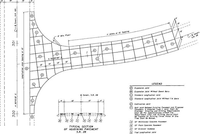
FIGURE 3.4 Layout of joints in rigid pavement at skewed intersection. Conversions: 1 in = 25.4 mm, 1 ft = 0.305 m.

Rigid Pavement Joint Sealing

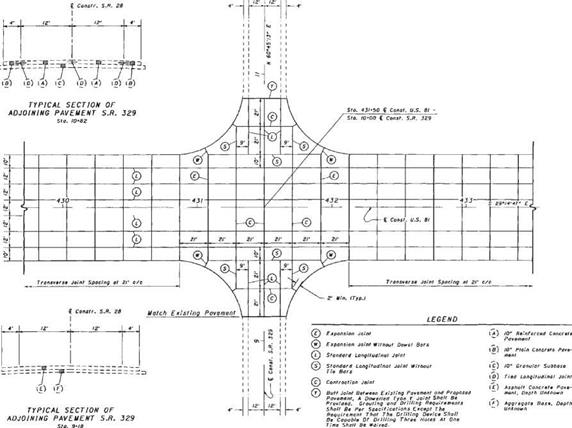
FIGURE 3.5 Layout of joints in rigid pavement at right-angle intersection. Conversions: 1 in = 25.4 mm, 1 ft = 0.305 m.


Подпись: 229

1/в" recess Top of pavement

Rigid Pavement Joint Sealing


Design Guide and in various articles in this chapter. With an unsealed joint, contraction under cooler temperatures allows joint cavities to open up and become filled with sand, stone, and other incompressible material. When warmer temperatures try to expand the length of the pavement, the joints are unable to close, compressive stresses develop, and spalling may result.

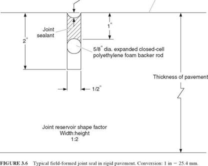
The purpose of a sealant reservoir (Figs. 3.1, 3.2, and 3.6) is to prevent water and incompressibles from entering the joint cavity. The design criteria for the sealant reservoir ensure that the sealant stays in place. The ability of the sealant to expand and contract with the movement of the joint is a function of the material properties of the sealant (defined by the manufacturer’s specifications) and the expected movement of the joint. Joint movement can be calculated using the following relationship:

AL = CL(A AT + Z) (3.3)

where AL = joint opening created by changes in temperature and loss of moisture during curing (joint movement), ft (mm)

C = constant used to adjust for friction between bottom of slab and the mater­ial that directly supports the pavement (0.65 for granular material, 0.80 for stabilized material)

L = joint spacing, ft (mm)

A = thermal coefficient of concrete, 10 6/°F (10 6/°C), multiplied by the following factors depending on coarse aggregate type: quartz, 6.6 (11.9); sandstone, 6.5 (11.7); gravel 6.0 (10.8); granite, 5.3 (9.5); basalt, 4.8 (8.6); and limestone 3.8 (6.8)

AT = difference in minimum temperature pavement will be subjected to and temperature at which pavement was placed, °F (°C)

Z = drying shrinkage coefficient of the portland cement concrete (PCC) slab, in/in (mm/mm). The coefficient depends on the indirect tensile strength, lb/in2 (MPa) as follows: 0.0008 for 300 (2.1), 0.0006 for 400 (2.8), 0.00045 for 500 (3.4), 0.0003 for 600 (4.1), 0.0002 for 700 (4.8)

(See “AASHTO Design Procedures for New Pavements,” FHWA Report HI-94-023, ERES Consultants, Inc., February 1994; and FHWA Technical Advisory T 5040.30, November 30, 1990.)

There are two categories of joint sealants. The field-molded sealant and the pre­formed compression seal are used extensively in rigid pavements. Also, field-molded sealants are gaining acceptance and being used in flexible pavements.

For field-molded sealants, the design is very simple and is controlled by the follow­ing relationship:

W = — (3.4)

where AL = joint opening to be accomodated, in (mm)

W = design width of transverse contraction joint, in (mm)

S = allowable strain specified by sealant manufacturer (typically 25 to 50 percent for field-molded sealants)

To control the strain in field-molded sealants, manufacturers recommend a reservoir shape factor (width to depth), and the use of a backer rod as illustrated in Fig. 3.6. The purpose of the backer rod is to prevent bond at the bottom of the sealant reservoir where the actual crack in the pavement exists. It is at this crack that the greatest strain will occur. Typical joint sealants are either asphalt-based or silicone-based.

For preformed compression seals, the uncompressed width of the compression seal should be chosen according to manufacturer’s specifications, as the material response characteristics are of primary importance. The calculated movement of the joint, normal­ized by the width of the uncompressed seal, should be less than or equal to the allowable movement of the compression seal, as determined by the manufacturer. Figure 3.7 shows a typical preformed seal installed in a pavement joint.

Heat Transfer in Soils

Ake Hermansson[6], Robert Charlier, Frederic Collin, SigurSur Erlingsson, Lyesse Laloui and Mate Srsen

Abstract Temperature highly affects pavement performance. High and low tem­peratures not only affects the viscosity of asphalt concrete but also has an impact on the moisture flow within pavements. At temperatures below 0°C the freezing of pavements dramatically changes the permeability and frost action might occur forcing water to flow upwards to the freezing front resulting in frost heave and other pavement distress.

Keywords Heat transfer ■ conduction ■ temperature ■ frost

4.1 Introduction

The thermal state may have a major influence on the moisture condition of a pave­ment or foundation. Thermal gradients due to temperature changes on the surface will induce not only heat flow in the pavement but also moisture flow.

Freezing and thawing are definitely the most important aspects linking temper­ature to water flow. Furthermore, a freezing temperature significantly reduces the permeability of soils but also increases the moisture flow caused by hydraulic gra­dients due to ice lens formation in the frozen soil.

Moreover, the water viscosity depends on the temperature; at higher tempera­ture, some water will flow in the vapour phase, and this depends on the temperature gradient. Heat flow and moisture flow are, therefore, linked processes with complex interaction between them. This chapter will describe the basis of heat transfer laws and models.

SOLID RAILING AT PORCH OR DECK

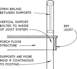
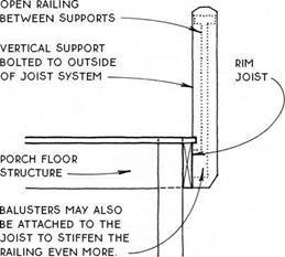
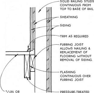
Open railings are connected to the floor of a porch or deck only intermittently, where the vertical supports occur. It is through these supports that open railings gain their rigidity. When the end of the railing is sup­ported at a wall or a column, no special connections are required. When the vertical support does not coin­cide with a rigid part of the structure, however, a rigid connection must be made with the floor system of the porch or deck. One logical place to locate this con­nection is at the inside edge of the rim joist (see the drawing below).

SOLID RAILING AT PORCH OR DECK

Another logical place to secure the railing to the porch floor is at the outside of the rim joist (see the drawing below). This is usually the most practical choice for waterproof decks, since the railing does not have to penetrate the waterproof surface.

SOLID RAILING AT PORCH OR DECK

However the railing is attached to the porch, its rigidity depends ultimately on the solid construction of the porch framing. Pressure-treated joists will con­tribute to the floor’s longevity, and metal hangers and clips will add rigidity. Block between joist bays when the railing is parallel to the joist system.

Waterproof deck with open railing—Waterproof decks surrounded by an open railing should be sloped away from the wall(s) of the building. Drainage may be distributed around all open edges, as shown below, or it can be collected in a scupper.

SOLID RAILING AT PORCH OR DECK

Open deck with open railing—Open decks sur­rounded by an open railing are relatively simple to drain. Be sure to provide adequate drainage from the surface below the deck.

(g) OPEN RAILING AT PORCH OR DECK

SOLID RAILING AT PORCH OR DECK

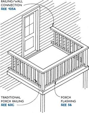
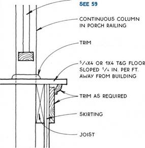
A wood porch with an open railing and a tongue – and-groove wood floor has been a tradition throughout the United States for the entire history of wood-frame construction and is still in demand. A tongue-and-groove porch floor is actually a hybrid between a waterproof deck and an open deck because although it is not water­proof, it is also not truly open like the spaced decking of open porch or deck floors. Moisture is likely to get trapped in the tongue-and-groove joint between floor boards and cause decay. To avoid this problem, the floors of these porches are often painted annually. Weather- resistant species or wood that has been pressure-treated will provide the most maintenance-free porch.

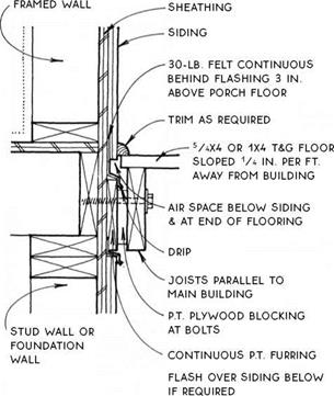
The tongue-and-groove wood porch was traditionally built without flashing. But for a longer lasting porch, the connection between the porch floor and the main structure should be flashed for the same reason as for all open porch and deck floors.

SOLID RAILING AT PORCH OR DECK

TRADITIONAL WOOD PORCH

Floor Characteristics

TRADITIONAL WOOD PORCH

Connection to Main Structure

OPEN RAiLiNG

SOLID RAILING AT PORCH OR DECK


1X4 T&G FLOOR

SLOPED

1/4 iN. PER FT.

AWAY FROM BUiLDiNG


JOiST NAiLED To FURRiNG JOiST through flashing


SOLID RAILING AT PORCH OR DECK

Подпись: TRADITIONAL WOOD PORCH Closed Railing TRADITIONAL WOOD PORCH

Open Railing

Подпись:Подпись:Подпись:Подпись:Подпись:SOLID RAILING AT PORCH OR DECKSOLID RAILING AT PORCH OR DECK

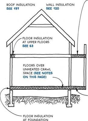
Floor insulation—Building codes in most climates require at least R-11 for floors over unheated spaces.

Installation—Floors over vented crawl spaces and other unheated areas are typically insulated with fiber­glass batts because the ample depth of the floor struc­ture can accommodate this cost-effective but relatively bulky type of insulation. The batts are easiest to install if weather and other considerations permit them to be dropped in from above. To support the batts, a wire or plastic mesh or wood lath can first be stapled to the underside of the joists, or plastic mesh can be draped very loosely over the joists.

SOLID RAILING AT PORCH OR DECK

support fiberglass-batt insulation with wire or plastic mesh, or with wood lath or wire AT 12 in. o. C.

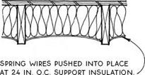
When crawl-space floor insulation must be installed from below, spring wires are cheap, easy, and effective.

SOLID RAILING AT PORCH OR DECK

Floor insulation over open areas that are exposed to varmints and house pets should be covered from below with solid sheathing (see 88A).

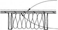
Vapor retarder—A vapor retarder is not always required in the floor structure over a crawl space because the temperature differential between the inte­rior space and the crawl space is not always enough to cause condensation. A floor over a heated basement or crawl space (see 8) would not require a vapor retarder. When conditions do require a vapor retarder or when an air-infiltration barrier (AVB) is desired, a 4-mil air/ vapor barrier may be placed on the warm side of the insulation, as shown in the drawing below.

vapor retarder can go on top of subfloor if unfaced batt insulation is below, or

vapor retarder can be integral with or on top side of insulation.

A vapor retarder placed on the subfloor is more con­tinuous than one on the top side of the batts, and it also will not trap rainwater during construction. Floor vapor retarders in any position are likely to accumulate mul­tiple nail penetrations and should be coordinated with the finish floor. For more on vapor retarders and air – infiltration barriers, see 120.

Perimeter insulation—Floors whose perimeter completes the thermal envelope, such as upper floors that are located over a heated space, need only be insu­lated at their perimeter, not throughout the entire floor. The continuity of insulation and air/vapor barriers at this location requires serious consideration (see 62B,

C & D and 63).

More to the south: hydraulic works at the second cataract

The pharaohs of the middle Empire tried to develop fluvial commerce with Nubia while at the same time protecting themselves from Nubia. Sesostris III extends the border of Egypt up to Semna, beyond the second cataract. A stela contains the following text: “Southern border established in year 8 of his majesty the king Khakaoure (Sesostris III), so as to prevent any Nubian from crossing it, by land or boat, neither any Nubian herds; except Nubians who would come to do commerce in Iken (Mirgissa), but not to the point that any Nubian boat travels to the north beyond Heh (at the northern outlet of the pass of Semna), 17

ever.

The pass at Semna is fortified to enforce this proclamation, and to tightly control traffic on the Nile. The water surface is artificially raised and the Nile flumes are blocked, so that boats can pass only through the narrow passage between the two forts constructed on each bank.

At the second cataract, the site of Mirgissa is also fortified. A slideway is built for hauling boats around the natural obstacle formed by the cataract rapids. Boats enter this slideway from a harbor built in the calm upstream waters (Figure 3.5). The slideway, likely from the reign of Sesostris III (around 1870 BC)[102] [103] has a useful width of about two meters, and is sloped to facilitate the hauling. It is lined with wood and silt kept damp.

More to the south: hydraulic works at the second cataract

Figure 3.5 Hydraulic works at Mirgissa, at the second cataract (schematic reconstitution from Goyon, 1986; Vercoutter, 1991).

FINE-TUNING FRENCH DOORS

Now it’s time for fine-tuning the installation or, as the pros call it, working the frame. Here are a few things you might see and what to do about each:

► Doors hitting in the center. Ease off the shims behind the jambs. If the problem is a bowed jamb, use additional nails to pull it back toward the RO or, better yet, use 2h-in. screws.

► Doors too far apart in the center. Shim out from the RO more. If that doesn’t work or if you must shim so much that the center of the jamb bows, the head jamb was probably milled too long and should be cut down. The gap between the double doors should be 54e in. or whatever the manufacturer suggests.

► Wider gap between doors near the top. Shim out behind a top hinge on one side.

► Uneven door heights, binding in a corner. One corner is lower than the other; drive a shim in under the jamb on the low side. Less likely, one jamb is too long. If you use a Japa­nese saw, you can cut the jamb in place; pull the nails tacking the jamb to the RO and then pry down from the top corner of the cut jamb.

► Doors aren’t in plane. The frame or RO is twisted. Use a level to see which element is out

image216Подпись:Подпись: Thumb-turn image218Подпись: PRO"ГIP Before drilling, chiseling, or routing a prehung door, insert wedges beneath it so it can't move. Alternatively, you can pull the hinges, remove the door from the frame, and support it in a pair of homemade door bucks, also called door-holding jigs. 1111

After the doors are set and the casing is installed, apply foil-faced, peel-and-strip flashing over the top flange of the head casing if the doors aren’t protected by an overhang. Note that this flashing overlaps the fiber-reinforced flashing on each side. To facilitate painting, the manufacturer premasked the lights with plastic film.

of plumb. If it’s the frame, pull the nails hold­ing it in place and push the high edges in and the low ones out. If the RO is racked (out of plane), use a sledgehammer as described earlier in this chapter to move the bottoms of the walls until you plumb them. Finally, if the walls and frame jambs are plumb, the door may be warped.

► The door won’t stay shut, or one hinge binds while the others work fine. See if the jamb is twisted. You may need to reset the shims until the jamb is square to the door. Otherwise, the hinge may be irregular. To correct it, use an adjustable wrench or locking pliers to bend the knuckles on one of the hinge leaves. Bend the leaf on the door, though, because you’ll probably split the jamb if you try to bend a leaf attached to it.

Rigid Pavement Jointing Details for Intersections

The following basic principles must be observed in developing a correct jointing detail:

1. Never taper concrete down to less than 2 ft (610 mm) in width.

2. Depending upon the amount of transverse reinforcing steel, be careful of the number of lanes that are tied together. In JPCP, tying more than three 12-ft (3.7-m) lanes together may result in uncontrolled longitudinal cracking.

3. Always design the secondary (intersecting) route as independent in movement from the primary route. Thus, as the primary route expands and contracts, no unnecessary forces will be created in the secondary route.

4. Provide for expansion wherever payment is interrupted in its longitudinal direction.

5. Terminate joints at 90° to any intersecting joints, obstructions, or edges of pavement.

6. Where possible, lay out lane widths of the same dimension. This permits the contractor to pave all the lanes without changing the paving machine setup dimensions.

7. Unless unavoidable, all joints should be in a straight line. Curved joints are diffi­cult to saw and generally require additional forming.

8. For plain (nonreinforced) concrete pavement, the slab length/slab width ratio should not exceed 2:1.

Intersection details should always be included in construction plans. A proper jointing layout ensures that cracking occurs at locations where load transfer exists (contraction joints) and away from wheel paths (longitudinal joints). The jointing detail should be a separate detail in the plan to eliminate confusion and allow field personnel to easily lay out the intersection without construction delay. Figures 3.4 and 3.5 show jointing layouts that have been used for typical intersections.