SIZING TALL STACKS

Sizing tall stacks will require you to use different sizing tables. A tall stack is one that has more than three branch intervals. Figure 4.19 and Figure 4.20 will show you the basics needed to size tall stacks for two different codes. There are differences in the number of fixture units allowed between the two codes. Since the tables are so much like others we have used, I won’t go into a lot of detail on them.

SUPPORTS

SIZING TALL STACKS

supports for drainage systems are needed. The distance between supports varies with the type of pipe being used and the local code that you are work­ing with. There are also differences between vertical and horizontal piping when you are designing your support placement. We could talk about this, but it would be faster and easier to just give you some reference tables to use when you need them. Figure 4.21 is for horizontal pipe with one code and

FIGURE 4.20 ■ Stack-sizing tall stacks in Zone Three (stacks with more than three branch intervals). (Courtesy of McGraw-Hill)

Maximum distance of supports (ft)


ABS

4

Cast iron

At

Galvanized (1 in and larger)

12

Galvanized (% in and smaller)

10

PVC

4

Copper (2 in and larger)

10

Copper (lVfc in and smaller)

6

Support material

Подпись: *Cast-iron pipe must be supported at each joint, but supports may not be more than 10 ft apart.

FIGURE 4.21 ■ Horizontal pipe-support intervals in Zone One. (Courtesy of McGraw-Hill)

Подпись: ✓ fast code fact Horizontal drainage pipe is required, normally, to be supported at a maximum interval of four feet.

Подпись: Maximum distance of supports (ft)

Figure 4.22 is for the same situation, but with a different code. Figure 4.23 deals with vertical pipes for one code, and Figure 4.24 shows vertical support requirements for a different code.

Type of drainage pipe

ABS

4

Cast iron

At

Galvanized (1 in and larger)

12

PVC

4

Copper (2 in and larger)

10

Copper (IV2 and smaller)

6

FIGURE 4.22 ■ Horizontal pipe-support intervals in Zone Two. (Courtesy of McGraw-Hill)

Type of drainage pipe Maximum distance of supports*


4 ft

At each story

At least every other story

At each storyt

Not mentioned

Not mentioned


Lead pipe

Cast iron

Galvanized

Copper

PVC

ABS


*A11 stacks must be supported at their bases. tSupport intervals may not exceed 10 ft.


Type of drainage pipe Maximum distance of supports (ft)*


Lead pipe Cast iron Galvanized

Copper (lVi in and smaller) Copper (IV2 and larger) PVC (ІУ2 in and smaller) PVC (2 in and larger)

ABS (ІУ2 in and smaller) ABS (2 in and larger)


4

At each storyt At each storyt 4

At each story 4

At each story 4

At each story


*A11 stacks must be supported at their bases. tSupport intervals may not exceed 15 ft. ^Support intervals may not exceed 30 ft.


FIGURE 4.24 ■ Vertical pipe-support intervals in Zone Two. [Courtesy of McGraw-Hill)

The Good, the Bad and the Sprawling

Over-consumption is reflected not only in the scale of our houses, but in the sizes of our yards and streets as well. Oversized lots on vast roads, miles from any worthwhile destination, have made the American suburb as inhos­pitable as it is vapid.

Like the design of our houses, the form of our neighborhoods is mandated by a long list of governmentally-imposed regulations that reflect our national taste for the enormous. In most U. S. cities it is currently illegal to build places like the older ones pictured in this book. Taos Pueblo, Elfreth’s Alley, and Rue de Petit-Champlain all violate current U. S. zoning ordinances. Narrow, tree-lined streets with little shops and houses sitting at the sidewalk’s edge are against the law. Countless state, federal and private bureaucracies work hard to uphold these restrictions. The Federal Housing Administration, the Department of Transportation, the auto, housing and oil industries and a host of others have a lot at stake in suburban sprawl and the policies that perpetu­ate it. Our government has been championing sprawl ever since the 1920s, when Secretary of Commerce, Herbert Hoover, persuaded realtors, builders, bankers, road-building interests and the auto industry to form a lobby that would push for increased development to boost the U. S. economy.

Essentially, zoning laws have been determining the form of our neighbor­hoods since the 1940s. Communities like the older ones pictured on these pages somehow managed without them. Since its inception, zoning has brought us immense, treeless streets, mandatory car ownership, and densi­ties so low that the cost of infrastructures has become nothing short of exor­bitant.

COMPOSITE PAVEMENT (OVERLAYS)

Rigid pavement constructed with an asphalt overlay is referred to as composite pavement. The advantage of constructing an asphalt overlay on a rigid pavement is solely in the areas of ridability and noise. Rigid pavements are considered by most to create more road noise inside a vehicle than flexible pavements. This phenomenon is largely due to the surface texture specified for rigid pavements to ensure proper skid resistance. By specifying an asphalt overlay with the rigid base, surface texture requirements can be relaxed and noise can be reduced.

There are few documented composite pavement design procedures available to determine the proper thickness ratios between the rigid base thickness and the flexible surface thickness. One way to determine an equivalent composite thickness buildup can be done using elastic layer theory. A convenient computer program called ELSYM5 (public domain) can be used for analysis of different layer combinations, provided the designer is willing to make some assumptions. By accepting the assump­tions, the designer is getting results that are only approximate but relative. ELSYM5 is based on elastic layer theory, which is not entirely appropriate for rigid pavement, since rigid pavement is not continuous, isotropic, and homogeneous in all directions. The procedure involves calculating the required rigid slab thickness for the conditions present where the composite pavement will be constructed. This is done using the AASHTO Pavement Design Guide or another method. The second step is to analyze the required rigid slab using ELSYM5 under the conditions designed for by calculating the deflections, strains, or stresses predicted under the maximum legal loading config­uration. Finally, using a trial-and-error procedure, replace up to 3 in (75 mm) of the rigid slab with enough thickness of asphalt to achieve the same deflections under the same loading scheme. A rule of thumb is to replace the first 1 in (25 mm) of slab thickness with 3 in (75 mm) of asphalt concrete. However, there is not a linear relationship of 1 in (25 mm) of PCC to 3 in (75 mm) asphalt concrete; for additional reductions in the rigid slab thickness, the elastic layer theory is relied upon to calculate equivalent deflections.

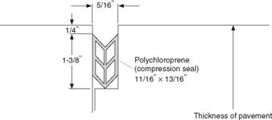
Because a composite pavement behaves more like a rigid pavement, special treat­ment is required for the transverse joints. Reflective cracking, cracks that propagate from the rigid pavement joint through the asphalt overlay, can be an intolerable distress which induces a rough riding pavement. The reflective crack allows water to enter, which induces stripping in the asphalt and slow deterioration into a spalled pothole. The suggested treatment to counter the reflective cracking is to saw and seal the asphalt con­crete overlay directly above the concrete joint. The joints should be sawed as soon as the asphalt overlay is placed, and the joint sealant reservoir should be constructed the same way as discussed previously. Figure 3.8 shows a joint in a composite pavement that has been properly sawed and sealed.

The pharaoh and the lake: the great hydraulic works of the IInd millennium BC

In prehistory the Joseph canal, or Bahr Youssouf, supplied water to Fayoum through an ancient arm of the Nile. At that time Fayoum comprised an immense body of water and marshes, with a water surface elevation somewhat below that of the Nile. Little by lit­tle, sedimentation raises the elevation of the plain. In about 7500 BC, hydraulic con­

nection of the region to the Nile is not continuous but episodic, causing periods of rising and falling lake levels. Throughout the IIIrd millennium BC, the lake level appears to have remained low, at an elevation that is thought by some to be around -2 m,[106] the level of the Nile being around +20 m at this time. At this time the large lake was natu­ral, occupying roughly the area within the contour 0 on Figure 3.6. The lake supported fishing, and hunting along its shores.

About 2000 BC, possibly because of an exceptional flood, the water level in the Fayoun Depression abruptly rose to +22 m, and then fell again.[107] This surge of water inundated Kasr el Sagah (founded about 2400 – 2300 BC) where there was an embarka­tion embankment. After this episode, men started to have a hand in the evolution of the lake, at the height of the Middle Empire. About 1890 BC, Sesostris II begins the exten­sive work that is eventually finished 50 years later by his grandson Amenemhat III,[108] the sovereign whom the Greeks later called Moeris.

The pharaoh and the lake: the great hydraulic works of the IInd millennium BC

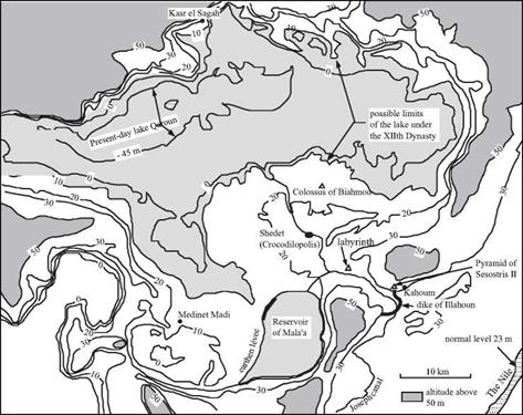
Figure 3.6 The Fayoum Depression and the “Moeris Lake”. We have shown on this map the 0,

10, 20, 30, and 50 m contours, from Ball (1939), as well as monuments and establishments of the XIIth Dynasty. Also shown are the hydraulic works (the Illahoun dike and the Mala’a reservoir) which have been dated in the 3rd century BC (Garbrecht and Jarritz, 1992). The normal level of the Nile is today at an elevation of 23 m; the flood level can attain 30 m.

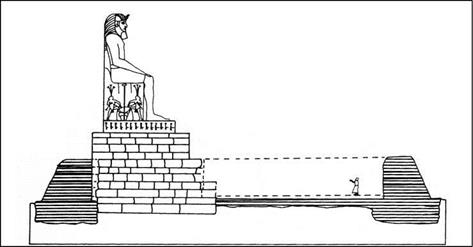
The work included widening the Joseph canal to 90 m, and building other irrigation and drainage canals. As a result, the now-cultivated region became an important eco­nomic center. The irrigation system undoubtedly used flood storage basins, as was the practice in Egypt. It is easy to suppose that the large artificial reservoir later recognized as Mala’a occupied the upper terraces to the south of the depression in one form or another, at an elevation sufficient to supply water to all of the region (there is no proof of this, however).[109] The capital of the Lake Province was then called Shedet (today Medinet el Fayoun), a city the Greeks will soon call Crocodilopolis since crocodiles are worshipped there. Amenemhat III had a tomb built so he could forever remain there, at Hawara. This is a pyramid associated with a vast temple called the labyrinthe, much admired by Greek and Roman tourists. This same king had a temple built near the pres­ent Medinet Madi, and another in the reconstructed colony of Kasr el Sagah. He also built two colossal statues at Biahmou, each twelve meters in height on a monumental pedestal, undoubtedly in his own image.

The pharaoh and the lake: the great hydraulic works of the IInd millennium BC

Figure 3.7 Amenemhat III looking over the Moeris lake – reconstitution of one of the colossi of Biahmou by the Egyptologist Sir Flanders Petrie (1899) (after Lane, 1985).

The Ptolemaic assertion that there were water control works at the entrance of Fayoun in this period (the Illahoun dike and its gates) has always been subject to some doubt. Yet one can see on Figure 3.6 that the monuments of the XIIth Dynasty are at an altitude of between +10 m and +20 m,[110] i. e. quite some distance below the flood level. Therefore it is easy to suppose that there must have been hydraulic works at Illahoun to isolate Fayoun from the rest of the valley and control the inflow of the Nile into the depression.

With the end of the XIIth Dynasty and of the middle Empire, in 1759 BC, came the troubles of the second intermediate period. During this period the maintenance of the Fayoun system was surely neglected. There is geological evidence of major inundations around 1700 BC, when the water level in the Fayoun Depression reached +22 m. Then again in 1500 BC it reached a record elevation of +24 m.[111] These floods were highly destructive, and the region never recovered its previous glory (at least not before the new developments of the 3rd century BC). Still, the region partially recovered in the period of the Ramses, when Fayoun hosted the great royal harem. A new series of troubles began in the 9th century BC, and with them surely came more uncontrolled incursions of the floods of the Nile into the Fayoun Depression. According to Butzer (1998), the water level in the Fayoun remains around +20 m from the 9th to the 5th century BC. It is easy to see from Figure 3.6 that the quasi-totality of the depression would be flooded at this level.

FLEXIBLE PAVEMENT

Asphalt concrete pavement, also referred to as flexible pavement, is a mixture of sand, aggregate, a filler material, and asphalt cement combined in a controlled process, placed, and compacted. The filler material can range from quarry crushing dust and asphalt-plant baghouse fines to wood fibers (cellulose). There are many additives that can be used in asphalt concrete mixes to encourage thicker cement coatings, more elastic mixes, stiffer mixes, and less temperature-sensitive mixes. Flexible pavements can be of a type constructed on a prepared subgrade, which is called full-depth asphalt concrete pavement (FDACP), or of a type built on an untreated granular base, which is not as carefully identified by the industry but is referred to herein as deep-strength asphalt concrete pavement (DSACP). (See Arts. 1.5.3 and 1.5.5.)

Flexible pavements are designed to bend and rebound with the subgrade. The design concept is to place sufficient layers of base and intermediate courses of pavement so as to control the strains in the subgrade so that no permanent deflections result. Loading of an asphalt pavement requires the stiffest layers to be placed at the surface with successively weaker layers down to the subgrade. The types and thicknesses of subbase materials placed above the subgrade should be selected with consideration of the strength of the subgrade. Very weak subgrades, after compaction, can lose compaction when very stiff aggregate bases are placed above. It is often advantageous to place a granular subbase, which is much weaker than an aggregate base, above weak subgrades to ensure that com­paction is sustained. Most, if not all, flexible pavement design procedures are based on a combination of elastic layer theory and experience. The elastic layer theory is used to cal­culate strains in each of the layers so as to ensure that excessive deflections will not occur. The experience is related to performance parameters that predict the number of times the pavement can bend (loadings) until cracking results.

The “marvelous” lake of Moeris. Fifteen centuries of work to devel­op Fayoum

The Fayoum Depression, located 80 km southwest of Memphis (see Figure 3.1) in the “lake province” of the ancient Egyptians, was prized by the pharaohs and viewed as a marvel by Greco-Roman travelers. Strabo wrote:

“(This region) contains also this admirable lake that is called the Lake of Moeris and has the

dimensions and color of a sea.”[104] [105]

This region has a long history. It was first developed at the beginning of the IInd millennium BC by the pharaohs of the XIIth Dynasty. It was visited by Herodotus in 460 BC, and redeveloped by the Ptolemite successors of Alexander in the 3rd century BC. Strabo visits the region in 25 BC, at the dawn of the Roman domination during which Fayoum was one of the granaries. Today, the Qaroun lake sits in the depression, 70 m below the normal level of the Nile, with its rather barren shores. The observations of travelers, geologists, and archaeologists regarding the depression are often contradic­tory. This has lead to divergent interpretations of the developments in this region. But in forming such interpretations one must not forget that the history of the region spans more than fifteen centuries.

Radiation

Radiation is a process by which energy moves through a medium or vacuum without the movement of any molecules and without heating any medium through which it passes. The quantity of energy radiated from a grain surface increases with increased surface temperature and neighbouring grains increase their temperature by absorb­ing the radiation emitted. Because the higher-temperature grains radiate more en­ergy, radiation results in a net transfer of energy to the lower-temperature grains. For coarse dry soils heat conduction is low and 10-20% of heat transfer can be due to radiation. Generally though, radiation plays a negligible role for heat transfer in soils.

4.2.2 Vapour Diffusion

Vapour moves towards a lower vapour pressure by a molecular process known as diffusion (fundamentally the same process that redistributes contaminants in static water as described in Chapter 6, Section 6.3.1.). There is no need for there to be a conventional pressure differential, only a difference in the concentration of the vapour. Vapour pressure decreases with decreasing temperature and with decreasing relative humidity. That is, cold and dry areas attract vapour. Typically, at micro­scale, water evaporates at the warm end of a pore and condenses at the cold end, thereby transferring latent heat from the warm to the cold end of the pore.

4.2.3 Convection

Convection is energy transfer by macroscopic motion of fluid (liquid and gas) parti­cles. The fluid motion is the result of a force. The force may be due to a density gradient or due to a pressure difference generated by, for example, a pump, by gravity or induced differences of density. The moving particles bring their high or low energy with them. In soils, typically, the moving particles which transport heat are water molecules. Density gradients may be due to a gradient of water or of salt content. Because the density of water varies with temperature, the density gradient may be due to temperature gradient only.

Mark exterior walls first

If the deck perimeter isn’t parallel and square, the walls won’t be either. Take the time to check this now, following the procedure explained in chapter 3 (see pp. 54-56). If nec­essary, lino-tune the exterior wall layout to correct for out-of-square corners or nonparal­lel walls. The lines you snap define the inside
edge of the exterior walls. For 2×4 walls, mea­sure ЗV: in. in from the deck edge (slightly more or less if you need to get the walls square and parallel). If the walls will be framed with 2x6s, use a 5’/-in. measurement. Instead of measuring this distance, you can simply lava scrap 2×4 (or 2×6) on the deck and mark against its inside edge. Mark all the exterior corners to establish the layout marks for snapping the exterior wall lines around the perimeter of the floor (or slab).

When you’ve marked all the comers, snap lines around the perimeter. If you’re working on a concrete slab, vou may want to move all these lines in an extra / in. so that the wall sheathing can be nailed onto the framed wall flush with the concrete. At this po nt, pay no attention to the openings for doors and windows—just snap the wall lines right through the openings.

Mark interior walls next

Begin laying out the interior walls by measur­ing from the exterior walls. For example, the illustration on p. 77 calls for a distance of

Mark exterior walls first12 ft. 7 in. from the outside comer of the house to the center of л partition wall. Add or subtract VA in. from that distance to snap the layout line for the partition wall. Remember to note how measurements are given on the plans. Layout long interior walls (such as hallways) first, then do the short walls (such as closets). There is no need to mark the door and wall openings.

For hallways, the minimum width is 37 in. in the rough, which yields a finished width of 36 in. (accounting for ‘A-in. drvwall installed on each side). I sometimes frame hallways 40 in. wide in the rough to create easier pas­sage tor a wheelchair (a standard wheelchair is 26 in. wide).

Pay particular attention to squaring bath­rooms and kitchens, which makes it easier to set cabinets and install vinyl flooring. When framing on a slab, plumbing lines will have been set in the concrete. If a pipe was placed slightly outside where a wall should be, its better to move the wall rather than the pipe. If the pipe misses the wall by a lot, you’ll need to involve a plumber.

Although a standard bathtub is 60 in. long,

I snap wall lines with a 60’Ain. space for the tub, which makes installation easier for the plumber. 1 also lay out the bathrooms plumb­ing wall with a 2×6 wall instead of a 2×4; a wider wall makes it much easier to fit all the bathroom pipes inside.

STEP2 Plate the Walls

This step involves laying out all of the lumber required for the top and bottom plates, cut­ting the plates to length, and temporarily tack­ing them on their layout lines so that match­ing marks can be made on both plates for the studs, doorways, windows, and ntersecting walls. Don’t plate, mark, and build one wall at a time. This old method is time-consuming
and makes it difficult to frame accurately. Instead, put all the plates down for every wall, beginning with the outside walls.

Подпись: Helping HandПодпись: "Tacking" is temporary. When a framing carpenter uses the word "tack," it means that parts are temporarily nailed together.It’s best to plate the long, outside through walls first, then plate the outside butt walls that extend between the through walls. As shown in the illustration above, through walls have plates that run through them from cor­ner to corner. Walls that ft between or inter­sect other walls are called butt walls. After vou finish plating the outside walls, you can move inside, beginning with the longest walls and working your way toward the shortest ones.

Continuously Reinforced Rigid Pavement

As the name implies, continuously reinforced concrete (CRC) pavement is a rigid pave­ment constructed with continuous longitudinal reinforcement. No transverse joints are installed. Instead, the pavement is allowed to develop random transverse cracks, and the steel reinforcement holds the cracked sections together. The size and spacing of the cracks are influenced by the percentage of reinforcing steel used. Current practice calls for 0.6 to 0.7 percent of the slab cross-section area. The design of the reinforce­ment is covered in the AASHTO Pavement Design Guide. The thickness of the slab is determined the same way as for other concrete pavements.

Continuously Reinforced Rigid Pavement

>

FIGURE 3.7 Typical preformed joint seal in rigid pavement. Conversion: 1 in = 25.4 mm.

A HORIZONTAL BRANCH

Подпись: *Table does not represent branches of the building drain, and other restrictions apply under battery-venting conditions. tNot more than two toilets may be connected to a single З-in horizontal branch. Any branch connecting with a toilet must have a minimum diameter of 3 in.

Let’s talk about how you can size a horizontal branch. Bet you can guess that we are going to use a sizing table. Hey, they’re easy, fast, and accu­rate, so why not use them? Look at Figure 4.16. This table shows you the maximum number of fixture units that may be placed on a single horizon­tal branch of a given size. If you look closely, you will see, once again, that not more than two toilets can be installed on a single 3-inch pipe that is in­stalled horizontally. It should also be noted that the table does not repre­sent the branches of a building drain and that other restrictions may apply if doing a series of battery venting.

Pipe size (in)

Maximum no. of fixture units

1 Vi

1

V/2

2

2

6

3

20t

4

160

6

620

A HORIZONTAL BRANCH

FIGURE 4.17 ■ Stack-sizing table for Zone Three. (Courtesy of McGraw-Hill)

STACK SIZING

A HORIZONTAL BRANCH

Stack sizing requires you to know the number of fixture units that will dis­charge into the stack from a single branch and the total number of fixture units that will be allowed on the stack. So, let’s say that you have a stack with two branches. There is a bathroom group on each branch, and those two bathroom groups are all that will discharge into the stack. What size pipe is the smallest allowable for use as the stack? To figure this, use the table in Fig­ure 4.17. So that you don’t have refer back to the fixture-rate table, I will tell you that each bathroom group is rated for six fixture units. Well, we have two toilets, so we know the pipe size must be at least three inches in diameter. With 6 fixture units per branch we might get by with a 2-inch pipe if there were no toilets involved. But, toilets are involved and the total load on the stack will be 12 fixture units, so we have to go with a 3-inch pipe. For infor­mational purposes, check out the sizing chart in Figure 4.18. Notice the dif­ference in the number of fixture units allowed on a branch with Figure 4.18 when compared to Figure 4.17. There are two codes at work in these exam­ples, and you can see that the difference for 4-inch pipe on a per-branch ba­sis is 70 additional fixture units with one of the codes.

FIGURE 4.18 ■ Stack-sizing table for Zone Two. (Courtesy of McGraw-Hill)

Fixture-unit discharge Total fixture

Pipe size (in) on stack from a branch units allowed on stack

І’Л 2 8

2 6 24

3 16* 60*

4 90 500


*N0 more than two toilets may be placed on a З-in branch, and no more than six toilets may be connected to a З-in stack.


FIGURE 4.19 ■ Stack-sizing tall stacks in Zone Two (stacks with more than three branch intervals). (Courtesy of McGraw-Hill)