WEATHERSTRIPPING JAMBS

Today, there are three main types of weather­stripping: tubular, metal-leaf, and kerf-in. Most are easy to install and require few special tools. Prehung doors usually come with weather­stripping attached, which can be a nuisance when installing the unit and trying to establish a uniform gap between the door and its jamb all around. Thus many installers remove kerf-in weatherstripping before beginning the installa­tion; it’s easy enough to slide the strips back into the kerfs when the job is done. Door shoe gaskets (which seal the bottom of a door) are removed for the same reason.

Tubular is the easiest to install on old doors and the least expensive type of permanent weather­stripping. The reinforced part of the strips is usually metal, with slots for attaching screws; slots allow you to adjust the stripping so it fits tight to windows or doors. To install tubular weatherstripping, shut the door and press the strip’s flexible seal against the door, then screw the reinforced part to the jamb; if it’s metal, use a hacksaw or aviation snips to cut it. Don’t buy tubular stripping that nails up or has round holes (not slots), because it can’t be adjusted.

Metal-leaf, commonly called a V-bronze or metal-tension strip, is a thin metal strip folded lengthwise and nailed with brads to door jambs. When the door shuts, it compresses the metal, stopping drafts. Metal tension strips are durable

image231

Kerf-in weatherstripping is essentially the same for doors and casement windows. Both compress the flexible stripping as they shut, sealing out drafts and moisture.

I Door Weatherstripping

image232

Kerf-in


TIP


Подпись: Because manufacturers often create a general hardware template for several different door styles, the template provided may be inaccurate. You may not need all the holes indicated, or you may need to reposition the template to accommodate a door edge bevel. So examine the door hardware and think things through before you mark or drill the door. If spindle holes don't line up perfectly after drilling, gradually enlarge them with a rat-tail file till they do. 1111

and, because they fit between the door or win­dow and its frame, are hidden when the door is shut. When installing it, place the leaves flush to the doorstop, spacing brads every 3 in. Install the head piece first, then the sides. To keep the leaves from snagging where they meet in the corners, snip them back at a slight angle (5°). In time, the leaves flatten, but they can be raised by running a flathead screwdriver down the center of the fold.

Kerf-in features flexible stripping (silicone, vinyl, foam) that slides into a kerf (slot) between the jamb and the doorstop. Kerf-in is the preferred weatherstripping for new prehung doors because it seals tightly and can be easily replaced if the

stripping gets worn out. To cut kerfs into existing frames, use a kerfing tool, which looks like a lami­nate trimmer on an angled base. Silicone stripping is a good choice for retrofits because it compresses so small that old doors shut easily without door­stop adjustments. At head-jamb corners, cut stripping at 45° angles so it lies flat.

CYLINDER LOCKSETS

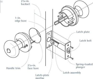
Cylinder locksets (also called tubular or key-in­knob locks) are popular because they’re cheap and easy to install. Better models have a spring – loaded dead latch that prevents the bolt from

DEAD B

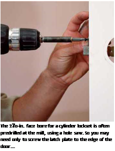
Подпись: I Cylinder Locksetimage226Подпись: Cylinder locks are relatively inexpensive and easy to install. Many interior doors come with the large face bore predrilled.Exterior doors should have a dead bolt with a minimum 1-in. throw (extension) and a reinforced strike plate that screws into the framing behind the door frame. Single-cylinder deadbolts have a thumb-turn on the interior that is easy to open in the event of a fire. Unfortunately, such thumb-turns can easily be turned by a burglar breaking a glass side light. Double-cylinder models, which require a key on both sides, are more secure but are frequently banned by fire codes.
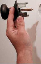
Подпись:image228"Подпись: .. .then insert the lock body into the spindle hole of the latch assembly, and screw the two handles together. Follow the instructions supplied with your lockset.image229image230

being retracted by slipping a plastic credit card between the door edge and the frame. But no cylinder lock is secure, because all can be snapped off with a pry bar or a swift kick. To be safe, install a dead bolt, too.

1. Using the template supplied by the manu­facturer, mark the centers of holes to be drilled into the face of the door (face bore) and the edge (edge bore). Use a 2f8-in. hole saw to drill the face bore. But after the tip of the hole saw bit emerges on the other side, prevent splitting by backing the bit out and finishing the hole by drilling from the other face.

2. Use a 18-in. spade bit to drill the edge bore, keeping the bit perpendicular to the edge. (Buy or rent a boring jig if you have a lot of locks to install.) Insert the latch/bolt assembly into the hole and use a utility knife to trace around the latch plate. Rout the inscribed area so that the plate is flush to the edge of the door.

3. Screw down the latch plate and insert the lock mecha­nism through the latch assem­bly. Try the handle; it should turn freely. Next, position the

strike plate on the jamb. To locate the strike plate exactly, rub a pencil on the end of the latch bolt, shut the door, and release the bolt against the jamb.

4. Using a 18-in. spade bit, drill a latch hole Я in. deep into the jamb. Center the strike plate over the hole and trace around it with a utility knife. Use a router to mortise the strike plate. Note: When the door is shut, the latch bolt should descend into the strike plate hole; the small spring-loaded plunger next to the latch bolt should not. Rather, the plunger should be stopped short by a lip on the strike plate.

5. For greater security, install a unit with a strike-plate reinforcer and З-in. mounting screws. To install the reinforcer, you’ll need to drill through the frame jamb into the framing behind; likewise, the extra-long screws will grab the framing.

Weatherstripping Door Frames

Air infiltration (drafts) can account for 20 per­cent to 30 percent of the total heat loss of an insulated house. If your budget is tight, caulking gaps and installing weatherstripping should be your first priority, even before insulating. The single most crucial piece of weatherstripping is a tight-fitting door threshold.

Step 16-Plumb & Line

String Line

Set 16d nail in corner of double plate and bend until it is in line with wall below.

“Plumb and line" is the process of making the walls straight and true.

“Plumbing" is the use of a level to set the ends of the walls plumb or perfectly upright.

“Lining" is using a tight string attached to the top of a wall as a guide for straightening it.

Set nails at either end of wall as shown, and then string line tightly between them, adjusting the line so that it is about W above the double plate. Wall should be moved in or out to align with string.

The walls are braced with 2 x 4 lumber to hold them and, if necessary, make them plumb and straight.

If a wall already is sheathed and in place, but not plumb, correct it if it is more than W out of plumb for standard height walls.

Pulling Brace


Double plate Top plate Wall

1. Push until wall is straight.

— Bottom plate


Temporary brace


2. Nail when wall is straight.


Push-brace


Blocks to hold brace


Step 16-Plumb & Line

Toenail push-brace

Relative Importance of the Different Mechanisms of Heat Transfer in Soils

4.2.5.1 Temperatures Below 0°C

The transfer of heat by conduction is the dominating factor at temperatures below 0°C (Sundberg, 1988). In the small pores of frost susceptible soils though, due to freezing point depression, some water remains unfrozen at temperatures below 0°C. This allows convection caused by so-called cryo-suction effects (see Section 4.6.2 below) and a small amount of heat transfer at temperatures below 0°C.

4.2.5.2 Temperatures Above 0°C and Below Approximately 25°C

At this temperature range, conduction of heat is still the dominating factor (Sundberg, 1988). In highly permeable soils there may be more forced convection – like groundwater flow that is natural or caused by water abstraction. High tempera­ture gradients in permeable soils may also cause significant natural convection.

4.2.5.3 Temperatures Above Approximately 25°C

For the lower temperatures in this range, conduction is still the dominating factor (Sundberg, 1988). At higher temperatures and relatively low water content, vapour transport gets successively more important. At saturation, heat conduction is always the dominating factor. Again, high temperature gradients in permeable soils may cause more natural convection. In coarse soils at high temperature, there will be more radiation but it will still play a minor role.

Laboratory Example

The relationship between the contents of air voids and coarse grains is well-illus­trated by the laboratory example described next.

Two mixes, identified by letters E and F, were produced in laboratory conditions to demonstrate the differences between SMA mixtures with the following different gradations:

• Mix E is characterized by a lesser discontinuity (more uniformity) of gradation.

• Mix F, designed according to U. S. gradation curves using NAPA SMA Guidelines QIS-122, has a much higher content of coarse aggregate particles.

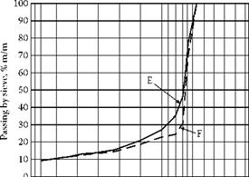
Both mixes were prepared with the use of a combination of sieves. The same combination has been applied to present gradation curves and to perform analyses of the aggregate mixes. The gradation curves of aggregate mixes E and F are shown in Figure 6.11. The aggregate mixes are compared in Table 6.12.

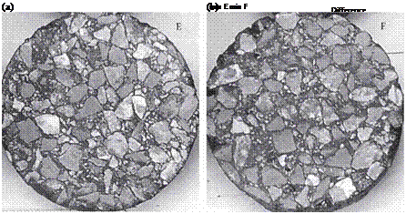
Figure 6.12 shows photographs of cross sections of the Marshall specimens of mixes E and F.

Mix F is distinguished by a higher discontinuity of gradation (aggregate 5.6/8 is missing from the composition) and a lower content of the sand fraction (by 2.5%). It is worth observing that the difference between contents of the fraction larger than 2 mm amounts only to 1.9%. The most significant differences appear on the 6.3 and

8.0 mm sieves. Differences between the mixes increase along with an increase in the sieve size. Mix F has been made in accordance with the U. S. gradation curves using NAPA QIS-122, which is based on an assumption that the direct contact within coarse

Подпись: so t--. o о d dПодпись: •Ф so со oom c-Подпись: Sieve, # mmПодпись: FIGURE 6.11 Grading curves of mixtures: E (solid line), F (dotted line)image530

10

20

30

40

50

60

70

80

90

100

TABLE 6.12

Laboratory Example

Composition of the Aggregate Mixes E and F

FIGuRE 6.12 Photograph of cross sections of Marshall specimens of mixes E and F. (Photo courtesy of Halina Sarlinska.).

chippings should be guaranteed—that is, the condition of stone-to-stone contact has to be satisfied. Both SMA mixtures were manufactured with the same fixed amount of binder (6.4% by mass), while the differences between them are obvious when com­paring the contents of voids in the Marshall specimens. The air void contents are as follows: mix E had 4.7% (v/v) and mix F had 5.2% (v/v).

Thus an increase in the content of coarse particles—and furthermore in the coarsest fraction of the coarse particles—brings about a definite opening of the SMA mixture. In other words, when moving the gradation curve toward higher contents of coarse grains, one should take into account the increase in the binder content, and probably the stabilizer as well.

The search for Lake Moeris

Among all the Greek travelers, Herodotus is the only one to have visited this region (in 460 BC) prior to the new hydraulic works implemented by Ptolemy II in the 3rd centu­ry BC. Having admired the Labyrinth, the funeral monument of Amenemhat III, he then describes a lake of very large dimensions, oriented approximately north-south:

“Such was the labyrinth; but an even greater marvel is what is called the Lake of Moeris, beside which the labyrinth was built. The circuit of this lake is a distance of about four hun­dred and twenty miles (670 km!), which is equal to the whole seaboard of Egypt. The length of the lake is north and south, and its depth at its deepest is fifty fathoms (89 m). That it is handmade and dug, it itself is the best evidence. For in about the middle of the lake stand two pyramids that top the water (these are the colossi ofBiahmou), each one by fifty fathoms, and each is built as much again underwater; and on top of each there is a huge stone figure of a man sitting on a throne. The water that is in the lake is not fed with natural springs, for the country here is terribly waterless, but it enters the lake from the Nile by a channel; and for six months it flows into the lake, and then, another six, it flows again into the Nile.”[112]

One would hope that this account reflects the work of the pharaohs of the XIIth Dynasty, but Herodotus’ account is from more than a thousand years later. Herodotus is in fact describing the rather sad sight of the depression’s complete inundation, consistent with the geological descriptions cited earlier. The dimension that Herodotus indicates (a perimeter of 640 km), and the fact that the colossi of Biahmou are “in the middle of the lake” leave no doubt that this is the case.[113] The alternating current in the Joseph canal was probably, at this period, a simple natural phenomenon caused by season variations in the level of the Nile, unregulated by man.

And yet, as we have said, there logically must have been one or more temporary reservoirs to store and distribute the flood waters in the era of Amenemhat III, distinct from the Qaroun lake that occupied the lowest portion of the depression. These reser­voirs were situated above the irrigated lands, very likely near Shedet – Crocodilopolis and the mouth of the Joseph canal. Field studies conducted in 1988[114] made it possible to reconstitute the boundaries of a vast reservoir, located on the heights to the south of the depression as expected. The southern portion of the boundary approximately follows the contour +17 m, and to the north it is closed by a dam. This dam of Mala’a is 8,000 m long and four to five meters high. But the only remnants of its masonry construction that are visible today date from the Ptolemites (3rd century BC) – along with remnants of repairs from the Roman and Islamic eras. Older vestiges have not been found. The visible traces of the Illahoun dike (remains dating also from the 3rd century BC) suggest that it was 5 km long and four meters high. It is unlikely that we will ever know the details of engineering developments from the period of Amenemhat III with any certain­ty. Since the Ptolemite engineers gave the ancient name lake of Moeris to their reser­voir, it is possible that their work more or less replicated the preexisting system – but this is only speculation.

There remains another question: what has been the evolution of the “normal” level of lake Qaroun across the ages of its existence? As we have seen, the altitude of the monuments erected in the XIIth Dynasty argue for a lake whose surface is approximate­ly at elevation +10 m. It rises to +20 m when the Fayoun Depression is not isolated from the valley, and fluctuates with the floods. In the Ptolemite period, as we will see later on (Figure 5.8), the new developments will be around elevation 0 (even -10 m), an alti­tude that is surely suggestive of the lake level at that time. It is likely not until the time of the Romans that the lake level was lowered to its present level, 45 m below sea level, to increase the amount of tillable land.

Fayoun owes its history as one of the most productive regions of Egypt to the hydraulic works of the successors of Alexander the Great. Strabo visits the region in 25 BC (the labyrinth remains one of the most attractive curiosities to travelers), long after these new works have been implemented:

“It still remains that the lake of Moeris, by its dimensions and its depth, is capable of contain­ing, during the floods of the Nile, the excess water, without overflowing onto inhabited places and their crops; and at the moment when the river waters recede, it is capable of returning this excess water by the same canal, in each of its two outlets, while keeping within itself and the canal, a reserve of water to feed the irrigation canals. Whatever be the acts of nature, they have placed locks (ports or gates?) by means of which the engineers regulated the flow of water that enters and leaves.” (Strabo, Book XVII, 1-37)

Thus it is indeed the great reservoir of Mala’a that Strabo describes as the “lake of Moeris ”, rendering unwitting homage to the nearby remains of the old pharaoh.

Streets Too Wide

One of the most readily-apparent products of zoning is the wide, suburban street. Roadways built before zoning emerged typically have 9-foot wide travel lanes. Now, most are required to have lanes no less than 12 feet wide. This allows for what traffic engineers call "unimpeded flow,” a term some crit­ics have aptly interpreted as "speeding”.

Safety concerns have played a no less significant role in the widening of America’s streets. During the Cold War, AASHTO (the American Associa­tion of State Highway Transportation Officials), pushed hard for streets that would be big enough to facilitate evacuation and cleanup during and after a nuclear crisis. Fire departments, too, continue to demand broader streets to accommodate their increasingly large trucks. Streets today are often fifty feet across because standard code after the 1940s has required them to allow for two fire trucks passing in opposite directions at 50 miles per hour.

Sometimes it is not a street’s width but its foliage that presents the problem. Departments of transportation routinely protest that trees [also referred to as FHOs (Fixed and Hazardous Objects)] should not line state roads. Now, cer­tainly safety is important, but the high costs of wide, treeless roads (financial and otherwise) might warrant some kind of cost/benefit analysis. Fortunately, we have several. The most widely published is that of Peter Swift, whose eight-year study in Longmont, Colorado, compared traffic and fire injuries in areas served by narrow and wide streets. He found that, during this period, there were no deaths or injuries caused by fire, while there were 227 injuries and ten deaths resulting from car accidents. A significant number of these were related to street width. The study goes on to show that thirty-six foot­wide streets are about four times as dangerous as those that are twenty-four

image30

image31

Streets Too Wide

image32

feet across. According to Swift’s abstract, "current street design standards are directly contributing to automobile accidents.”

This study and others like it suggest that we should begin to consider the issue of public safety in a broader context. Fire hazards are only part of a much larger picture. The biggest threat to human life is not fire but the count­less accidents caused by America’s enormous roadways.

Suburbs did not grow out of any particular human need or evolve by trial and error as an improvement to preexisting types of urbanism. The ‘burbs, as we know them, were invented shortly after World War Two as a means of dis­persing urban population densities. This invention precluded virtually all les­sons learned from the urban design of years past. Even the most universal principles of good planning, used successfully from 5000 B. C. Mesopotamia to 2005 A. D. Seaside, Florida, were ignored. Perhaps the most startling de­parture from tradition was the omission of contained outdoor space. Human beings have a predilection towards enclosure. We like places with discernible boundaries. To achieve this desired sense of enclosure, a street cannot be too wide. More specifically, its breadth should not far exceed the height of the buildings that flank it. A street that is more than twice as wide as its buildings are tall is unlikely to satisfy our inherent desire for orientation and shelter. Rows of trees can sometimes help to delineate a space and therebyincrease the recommended street-to-building ratio, but generally, anything wider than a proportion of 2:1 will compromise the quality of an urban environment.

America’s suburbs incessantly ignore the 2:1 rule. The distance from a house to the one directly across the street is rarely less than five times the height of either structure, and there are seldom enough well-placed trees around

Подпись: 51Sprawl, U. S.A. (pages 48 & 49). Quebec City (opposite)

to compensate. The empty landscape that results is one most of us have become far too familiar with.

To evoke a sense of place, a street, much like a dwelling, must be free of use­less space. When given a choice, pedestrians will almost always choose to follow a narrow street instead of a wide one. That we frequently drive hours from our suburban homes to enjoy a tiny, lakeside cabin or the narrow streets of some old town is nearly as senseless as it is telling. That we then return to toil in our cavernous dwellings on deficient landscapes is more sense­less, yet. The environments we see pictured in travel guides are typically the walkable, little streets of our older cities. The marketing agents who produce these guides are undoubtedly no less aware of our desire for contained, out­door space than were the architects of the streets depicted.

People like places that were designed with people in mind, so it should come as no surprise that property values and street widths appear to share an in­verse relationship. Apparently, we are willing to pay more for less pavement. The funny thing is that the skinny streets we like are actually much cheaper to build and maintain than the wide ones we so often choose to live with.

image33

Quebec City

DEVELOPMENT OF AASHTO PAVEMENT DESIGN EQUATIONS

Perhaps the most widely used pavement design method in the United States and throughout the world is that presented in the AASHTO Guide for Design of Pavement Structures. A long history of pavement studies has led to the current (1993 with 1998 supplement) edition.

DEVELOPMENT OF AASHTO PAVEMENT DESIGN EQUATIONS

FIGURE 3.8 Joint in composite pavement that has been sawed and sealed.

The developments leading to the current AASHTO design procedure began with the Bates Experimental Road, which was constructed in 1922 near Springfield, Illinois. The purpose of the experimental road was to determine what factors affected pavement per­formance. The researchers found that pavement performance could be correlated with truck loading. No further major research was conducted over the ensuing 25 years.

The changes in truck configuration and expansion of the highway network resulting from World War II brought pavement performance to the forefront again. In 1949, the Council of State Governments held a meeting in Columbus, Ohio. At this meeting, highway officials decided there was a “need for more factual data concerning the effects of axle loads of various magnitudes on pavements.” The effort to advance the science of pavement design was led by the American Association of State Highway Officials (AASHO, which later became AASHTO). The regional AASHO associations decided to construct test pavements in each region. The first of these test roads was constructed by the Southeastern AASHO states. Named Road Test One, two test loops were con­structed in 1950 near La Plata, Maryland, each loop containing two 12-ft-wide (3.7-m) pavement lanes. All sections constructed were concrete with a pavement thickness of 7 in (178 mm) thickening to 9 in (229 mm) at the edge of the pavement. Each lane of a loop carried only one loading and axle configuration.

A second regional test road was constructed by the Western Association of State Highway Organizations (WASHO). Named the WASHO Road Test, two test loops were constructed in 1952 near Malad, Idaho, each consisting of two 12-ft (3.7-m) lanes. All pavement was comprised of asphalt concrete on a crushed aggregate base, constructed on subbases from 0 to 16 in (406 mm) thick. Each lane of a loop carried only one load­ing and axle configuration. Because of the limited number of sections constructed in Maryland and Idaho, a rational design procedure could not be developed.

In 1951, support was growing within AASHO for an expanded road test. This led to the construction of the AASHO Road Test near Ottawa, Illinois, which contained six loops with two 12-ft (3.7-m) lanes. The AASHO Road Test contained 468 asphalt sec­tions and 368 concrete sections. Each lane of a loop carried only one loading and axle configuration. A total of 1,114,000 load applications were applied over a 2-year period.

The rigid pavements in the AASHO Road Test were concrete slabs ranging in thickness from 2lA to 121/2 in (63 to 317 mm) thick. The slabs were placed either on a granular subbase or directly on the subgrade. Flexible pavements at the AASHO Road Test consisted of asphalt pavements placed on a base and/or subbase. As confirmed by these tests, rigid pavements carry traffic loads through beam action whereas flexible pavements carry traffic loads by spreading the stress through the underlying layers.

Unpublished preliminary results from the road test were released to the states in 1961 and 1962. The AASHO Interim Guide for Design of Pavement Structures was published in 1972. Chapter 3 of the interim guide was revised in 1981. The first edition of the AASHTO Guide for Design of Pavement Structures (1986) introduced many new con­cepts including the reliability concept. It was published in two volumes, the first giving design procedures and the second providing documentation and explanatory information. The second edition of the guide was published in 1993 and a supplement in 1998.

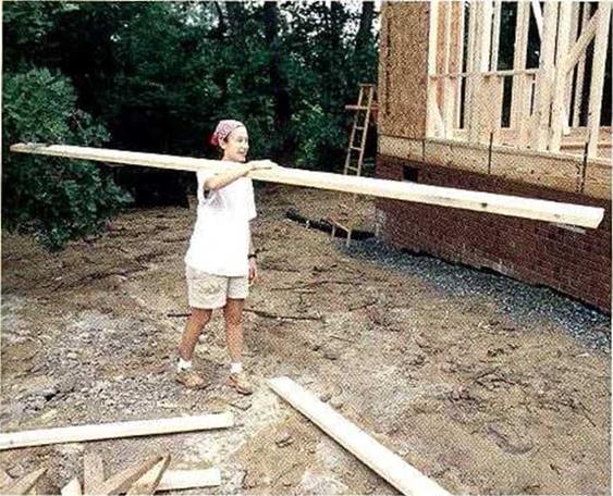
Techniques CARRYING LUMBER

Techniques CARRYING LUMBER

FRAMING LUMBER CAN be heavy.

A 2×4 stud isn’t a big deal, but a wet, 16-ft. 2×12 sure is—and there are many boards of that heft even in a small house. Dor’t carry lumber by holding the board at your waist; this puts undue strain on your elbows and lower back. Instead, grab a long, heavy board at its balance point and, in one fluid motion, lift and flip it gently onto your shoul­der. With your entire body helping absorb and distribute the weight, the load is much easier to carry.

Подпись: 6]/4 in. (top cripple length) Make a story pole from a 2x s:ud. This pole will help you accurately lay out trimmers, headers, rough sills, and top and bottom cripples.

Tool Talk MAKING A STORY POLE

THE BEST WAY to obtain accurate lengths for cripples and trimmers is to make a story pole. As the name sug­gests, this straight length of wood (I use a 2×4) tells a story. In this case, it’s the description of a wall layout, with the locations of sills and headers for windows and doors providing the measurements for cutting cripples and trimmers. Wi:h a story pole, you do all the measur­ing once, double-check everything, then use the pole as a reference for the entire layout. Instead of repeatedly measuring crip­ples and trimmers with a tape measure, you simply transfer the layout marks from the story pole.

To make a story pole, select a straight stud and nail a short scrap of 2×4 on one end to act as the bottom plate. Then, mea­suring upward from the

base of the bottom plate, clearly mark the underside of the header at 6 ft. 10 in. (assuming that is the header he’ght). Measure upward another VI? in. for a single flat header, ЗУг in. for a 4×4 header, and 5У> in. for a 4×6 header, making clear marks across the story pole. The distances remaining above the header layout lines are

the lengths of the top cripples. Remember that headers for pocket and bifold doors may be higher, so their cripples will be shorter. Label the layout lines on your story pole to avoid confusion.

To locate windowsills, mea­sure the window height down from the bottom of the header. Measure down another Г/г in. for a single 2x rough sill. The amount remaining is the length of the bottom cripples. The trimmer lengths are measured from the bottom plate to the bottom of the header.

Подпись: Helping HandПодпись: "Scrap" pieces are valuable. It's smart to collect and organize the offcuts that accumulate as you cut plates, sills, and other wall parts. (This is a great job for one or two volunteers who haven't worked on a construction crew before.) Shorter pieces of 2x lumber can be used to make essential small parts, such as top cripples and blocking.

STEP3 Count and Cut the Headers, Rough Sills, Cripples, and Trimmers

1 helped build my first house in 1948. It was a mail-order house brought to our small town by the Chicago and Northwestern Railroad, then to the site by horse and wagon. Every piece of the house frame was precul and tied in bundles. My job was to untie the bundles and bring the pieces to the carpenters who nailed them together.

Today, the same house pieces are needed, but most of them are cut to length on site. Headers are needed over door and window openings to transfer roof loads down to the
subfloor and foundation. Rough sills support windows. Cripples or jack studs either support a rough sill or transfer weight from a top plate to a header. Trimmers extend on both sides of door and window openings lo support head­ers (see the illustration on p. 84).

Before you can begin cutting or marking framing members, you need some basic infor­mation, including the standard stud length, the height at which headers will be set, the size and location of door and window openings, and the way in which headers will be con- siructed. A good wav to carrv around this

о t і

information is with a story pole, <> explained in the sidebar above. Recording wall-building

WAYS TO PLATE WALLS

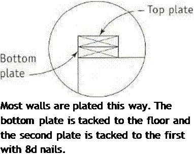
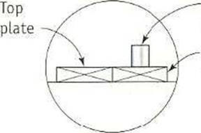
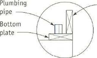
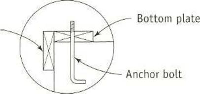
Подпись: Most walls are plated this way. The bottom plate is tacked to the floor and the second plate is tacked to the first with 8d nails. WAYS TO PLATE WALLSПодпись: Top plate Подпись: Two ways to plate walls that house pipesWAYS TO PLATE WALLSПодпись: Top plateПодпись: On exterior walls with bolts, hang the top plate on the outside.WAYS TO PLATE WALLSStack, tack, and cut

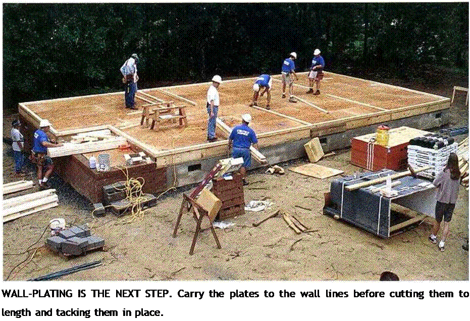
Plating a wall involves three procedures.

STACK THE PLATES. Place two layers of plate slock (2x4s are used for the wall framing on this house) along the layout line for the wall. These layers will become the top and bottom plates. Reserve the straightest 2x4s for the plates, and use the longest plates (typi­cally 16 ft.) on the longest exterior walls. Pay attention to where the top plate stock hulls together. These butt joints should be at least 4 ft. away from an intersecting wall.

TACK THE PLATES IN PLACE. After you’ve dis – trihuted the plate stock, you can start tacking it down. Using 8d nails, tack, or temporarily nail, the bottom plate to the subfloor right on the line. Drive an 8d nail about 1 ft. from the end of each board and another near each intersecting wall. Tack the top plate directly on top of t he bottom plate. Continue stacking and tacking until you reach the end of the wall.

Helping Hand

Подпись:Select straight plates. Check 2x plate lumber for bow and twist and select only the straightest boards for plates. This makes for strong, straight walls.

Подпись: Helping HandПодпись: Add anchor bolts to slabs. Anchor bolts need to be within 1 ft. of the end of a wall plate. If necessary, additional bolts can be epoxied into holes drilled in the slab, or suitable masonry anchor bolts can be installed.

CUT THE PLATES TO LENGTH. As vou’re stack-

4

ingand tacking, you’ll also be cutting plates to length with a circular saw. Where 2x plate stock butts together, make sure that the ends are square-cut and that they meet snugly. Although it’s acceptable for the bottom plate to be a little short, the top plate must be as close as possible to the exact length. The bottom plate of a framed wall is nailed to the subfloor. Roof trusses arc na led to the top plates.

When the outside walls have been plated, you can start scattering plate stock for the interior walls. Don’t do this haphazardly, lust as when you were laying out the walls, its best to plate the long, parallel interior walls first. These long walls become through walls into which shorter walls butt. Plate the shortest

walls last. Pav attention to which interior walls

/

are butt walls and which ones are through walls. If the walls are plated properly, it is eas­ier to build and raise them. I run all plates
continuously, ignoring door and window openings. The bottom phr. e will be cut from the door openings later.

Plating on a concrete slab and around plumbing

When working on a slab with anchor bolts, use an anchor-bolt marker to locate the holes in exterior wall plates (see p. 57 for more on anchor holts). After the holes are drilled, you

4

can fit the bottom plate or the anchor bolts and nail the top plate along the bottom plate’s outside edge (see the illustration on p. 80). It can also be toenailed on edge to the top of the top plate.

If you encounter plumbing in the walls, cut the bottom plate to fit around the obstruction. You can place the top plate alongside the bot­tom plate or toenail the top plate on edge to the bottom plate. These plating strategies maintain the alignment of the top and bottom plates so that your markings will be accurate.