U. S. METHOD

This method emerged in 1990 after a tour of Europe when some U. S. engineers learned of the benefits of SMA. A series of research efforts started soon after to develop a method of designing SMA. This resulted, among other things, in publica­tions (Brown and Haddock, 1997; Brown and Mallick, 1994) that tried to reach to the heart of the matter of SMA mixtures and suitable methods of designing and testing them.

The essential aspect of designing an SMA aggregate mix using the U. S. method is the introduction of the idea of stone-to-stone contact, or a direct contact among coarse particles. Those grains, called active grains, make a strong mineral matrix and give the SMA its deformation resistance. The method of testing the stone-to-stone contact has also been defined. It is called the dry-rodded test and will be explained later in greater detail. Designing SMA in the United States has been described in different publications (e. g., in NAPA SMA Guidelines QIS 122 and the standards AASHTO M325 and AASHTO R46). The method described in these guidelines will be discussed here. It consists of the following stages: [28]
mix exceed 0.2 g/cm3, the composition of an aggregate mix should be converted from mass into volume, and only such values can be compared with gradation limits (the requirement using AASHTO MP 8-00, currently M325).

7.2.2 Stage 2: Selecting a Gradation Curve

Composing an adequate aggregate mix is the crucial step in the design process. Adequate in this case means meeting the following conditions:

• A design gradation curve lying between the gradation limits

• Suitable contact among coarse particles—that is, the fine aggregate and filler do not interfere with the contact among the largest particles (the stone – to-stone contact is guaranteed)

When the standard method is used, at least three trial aggregate mix composi­tions are designed, with their gradation curves lying close to the upper, middle, and lower gradation boundaries of the allowable ranges of gradation. Obtaining three such curves involves changing ratios between the fine and coarse aggregate contents.

The quantity of filler is generally assumed to be constant, depending on the size of the SMA’s biggest particle. With that in mind, the content of particles smaller than 0.075 mm should amount to approximately 14% (m/m) in the finest SMA 0/4.75 mm, while in coarser SMA mixtures the filler content should be approximately 10% (m/m). With the filler amount essentially fixed, the ratio between coarse and fine particles may be changed to adjust the position of the SMA aggregate mix gradation curve.

U. S. METHOD
image55 image56,image57,image58

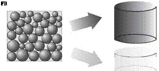
How do we secure contact between the coarse particles? Before discussing this, the aggregate mix should be remembered. The volume division between coarse (skeleton, active) particles and fine ones (filling, passive) is displayed in Figure 7.2. As shown, this division displays a strong particle skeleton made up of appropriate coarse grains. The term coarse aggregates has been intentionally omitted because,

FIGURE 7.2 The volume distribution of the elements in a mineral mix.

after all, the particles are bigger than 2.36* mm; however, these are too small to create a strong skeleton. The boundary sieves for SMA mixtures (called breakpoint [BP] sieves), from which the coarse skeletons start, depend on the following nominal maximum aggregate size (NMAS[29] [30]) of the mixture:

• NMAS > 12.5 mm BP sieve: 4.75 mm

• NMAS = 9.5 mm BP sieve: 2.36 mm

• NMAS = 4.75 mm BP sieve: 1.18 mm

The most common mix is probably SMA 0/12.5 mm with the 4.75 mm BP sieve. According to the method, the skeleton making aggregates are 4.75 mm or larger. So these particles are not simply chippings but a slightly coarser aggregate. A 0/9.5 mm SMA with the 2.36 mm BP sieve has a skeleton made up of typical coarse fraction only (i. e. larger than 2.36 mm).

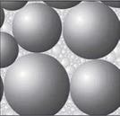
Now let us look again at an SMA 0/12.5 mm. Coarse grains making a skeleton have to be in contact with each other. Next let us consider a compacted layer consist­ing only of coarse aggregate particles. During compaction, the particles will become interlocked tightly so that they will come to rest against each other; and there will be nothing to prevent them from touching. As a result, we have the full, 100% stone – to-stone contact we are aiming at. Now, looking at that compacted layer of coarse aggregate, we can easily see some free space among the coarse particles. If we are able to insert passive (filling) particles into that space, then our aim of preventing the coarse particles from being shoved aside will be achieved. Putting it in a nutshell, particles smaller than 4.75 mm cannot have a higher volume than the remaining air voids in the compacted skeleton part. This way of packing the mix is displayed in Figure 7.3.

image59 U. S. METHOD

Further steps are self-evident; because all particles bigger than 4.75 mm create the aggregate structure, they have to be examined separately from the aggregate

mix. The next objective will be determining the air voids in a compacted coarse aggregate—namely, the space for filling aggregates.

Safety on the Job MAKING A LAYOUT STICK

Подпись: ISafety on the Job MAKING A LAYOUT STICK

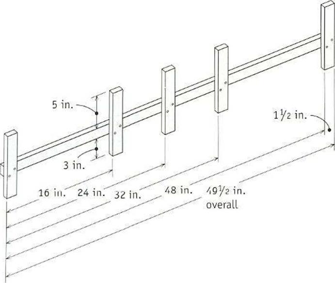
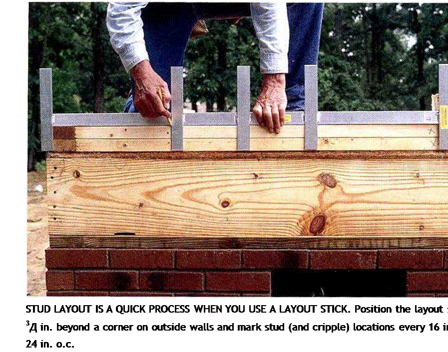
WHETHER YOU USE a store-bought layout stick or make your own, this tool will save you a lot of time when marking plates in preparation for wall con­struction. A stick like the one shown here can be used to lay out studs on 16-in. and 24-in. centers.

To make your own layout stick, cut a series of ІУг-in.-wide strips from a panel of 34-in.-thick ply­wood. Cut one strip 497? in. long and five strips 97? in. long. Glue and nail the short pieces to the long piece at right angles and at the spacing shown in the illustration. The З-in. legs allow you 😮 mark top and bottom plates at the same time. The 5-in. legs make it easy to mark two plates side by side and to mark headers and rough sills along with the plates.

indicate the studs’ locations. This will give vou a 14k:-in.-wide rough opening for the medi­cine cabinet. Write UMC>> on the plates between the two stud locations.

Include blocking requirements when mark­ing up plates. As explained in the sidebar on p. 89, blocking between studs provides solid backing for important items, such as towel bars, built-in shelves, and so on, which will be installed after the interior walls are finished. II you’re building a porch, this is also the time to mark the location of any porch beams (see chapter 6). Porch beams recess 3 in. inside the walls and require two trimmers underneath to support them.

Mark stud locations last

1 don’t know who made the first layout stick for marking stud locations, but I have been using one for almost 50 years. You can either make one (see the sidebar above) or buy one (see Resources on p. 278). 1 learned howto do stud layouts with a long tape and a small square, but 1 think it is taster and easier to use a layout stick.

Take a look at the building plans. Exterior walls generally have studs spaced 16 in. o. c. Interior wall studs may also be spaced 16 in.

o. c. but are more often 24 in. o. c. When exte­rior walls arc sheathed with plywood orOSB, the studs arc spaced to fit these 4-ft. sheets.

Start the stud layout at one end of a long exterior wall. Place the layout stick on the out – side edge of the plates, with the first tab rin.

Подпись:Safety on the Job MAKING A LAYOUT STICK

beyond the end of the wall. This sets up a 16-ІП.-О. С. or a 24-in.-o. c. layout that will accommodate the 4-ft.-vide sheathing sheets (see the photo at right). Mark both sides of the remaining tabs to note the locations of the next three studs. Move the layout stick, line up the end tab with the last mark, and mark again. ІГ you’re nailing a sheet of OSR at the outside corners for bracing, make sure you lay out a stud 4 ft. from each comer in both directions.

When you come to a door or window

»

opening, just continue the stud layout, mark­ing cripple locations on the headers and the rough sills. Lay out all exterior walls and then begin on the interior walls. The layout of inte­rior walls is not as critical as that of exterior walls, because most drvwall hangers use long

j О О

sheets of drvwall, which often run from corner to corner, fust put the stick in a corner against a through wall and start marking. Make sure you put the stud markings on the same side of the plates as the header markings. When you encounter rough plumbing, don’t pat a stud next to a pipe. Give the plumbers room to fin­ish their work. Kach intersecting wall automat­ically has a stud on each end, so there’s no need to mark those locations.

Old codes required that a stud be placed tinder every break in the top plate. Here in the West, this hasn’t been a requirement for nearly 40years, but check with your local building inspector. My guess is that few, if any, areas in

the country still require it. As long as you have a double top plate, locating a stud under a plate break adds little to the structural integ­rity of the frame.

Because of the sheer number of marks required on walls, it’s a good idea to walk through every “room” after you have finished marking all the plates. Visually check whether all of the wall plates, headers, rough sills, cor­ners, and channels are proper у marked. The time you take to inspect your work now can save vou much more time later. It takes a lot

4

longer to tear out studs and frame a door that was missed during layout than it does to take a leisurely but focused stroll through the house to make sure everything is in order.

||

X

h

O

S

CL

3

z

X


Before we can nail the walls together, other parts


Driving nails is satisfying work, whether you use a


must be assembled. . .


pneumatic nailer or a hammer. . .


W7.

-vjby

I

W, __


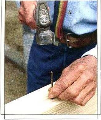
Подпись: Helping HandПодпись: Dull tips are useful! When you need to drive a nail near the end of a board, first blunt the tip of the nail. This helps prevent splitting the wood.Safety on the Job MAKING A LAYOUT STICKSafety on the Job MAKING A LAYOUT STICK

Services Too Dispersed

Zoning as we know it basically began in nineteenth-century Europe. Indus­trialized cities were shrouded in coal smoke, so urban planners rightly sug­gested that factories be separated from residential areas. Life expectancies soared, the planners gloated, and segregation quickly became the new solu­tion to every problem. So, while in the beginning only the incompatible func­tions of a town were kept apart, now everything is. Housing is separated from industry, low-density housing is kept separate from existing, higher-density housing, and all of this is kept far from restaurants, office buildings and shop­ping centers, which are all kept separate from each other.

With the dispersal have come mandatory car ownership and the end of pe­destrian life as we once knew it. Where no worthwhile destinations can be easily reached on foot, there are no pedestrians, and where there are no pedestrians, there is no vitality.

This separation has simultaneously brought about an increase in the per­ceived need for ultra-autonomous houses. The idea that a house should con­tain everything its occupants could ever possibly need and then some is cer­tainly not a new one, but it has achieved unprecedented popularity as houses have become increasingly remote from the services they traditionally relied upon. It now seems that every new residence must contain not only its own washer, dryer, dishwasher, high-speed internet access and big-screen home entertainment center, but enough kitchen, bathroom, dining and living space to serve as a nightclub for forty. The needs fulfilled by the corner grocery and local bar in our older neighborhoods are now assumed by 700 cubic-foot re­frigerators and spacious, walk-in pantries. The resources currently required to support several million personal outposts cannot be sustained.

Volumetric Parameters

The volumetric relationship in an asphalt mixture is shown schematically in Figure 7.1 in German terms. Equations are based on TP A-08 2007 and Hutschenreuther and Woerner (2000).

Symbols in Figure 7.1 include the following:

Hbit = Volume of voids in compacted asphalt samples, % (v/v)

Bv = Binder volume, % (v/v)

Mv = Mineral aggregate volume, % (v/v)

HMbit = Voids in mineral aggregate (VMA), % (v/v)

Obviously, the sum of all the parts should equal 100%.

MV + BV + Hbit = 100%

The way of calculating volume parameters and defining them is outlined here.

Подпись: Hhit

Volumetric Parameters Подпись: Binder volume

Air voids

Aggregate volume

Mv

FIGURE 7.1 Volume relationship in an asphalt mixture according to terminology adopted in Germany. (From Graf, K., Splittmastixasphalt—Anwendung und Bewahrung. Rettenmaier Seminar eSeMA’06. Zakopane [Poland], 2006. With permission.)

Volumetric Parameters

The binder volume in an asphalt mixture

В = Binder content in the mixture, % (m/m)

pA = Bulk density of the asphalt mixture (sample), g/cm3

pB = Binder density at a temperature of 25°C, g/cm3

Volume of mineral aggregate

Подпись: MV =Pa (100 – В)

pR, M

pA = Bulk density of the asphalt mixture (sample), g/cm3 В = Binder content in the mixture, % (m/m) pRM = Density of the aggregate mix, g/cm3

Content of air voids in compacted asphalt mixture

Hbit = PR-bit Pa -100%

PR, bit

pA = Bulk density of the asphalt mixture (in German Raumdichte), g/cm3 pRbit = Maximum density of the asphalt mixture (in German Rohdichte), g/cm3

Air voids in compacted mineral aggregate (the hypothetical voids content)

HM, bit = Hbit + BV

Bv = Binder volume, % (v/v)

Hbit = Air voids in the compacted asphalt mixture, % (v/v) Voids filled with a binder

hfb = -^- • 100%

HM, bit

Bv = Binder volume, % (v/v) HM, bit = VMA, % (v/v)

7.1.3 Comments

• In most cases of designing an SMA, the steps described in Section 7.1.1 are sufficient.

• The void contents in compacted Marshall specimens after the application of various compactive efforts (2 x 50 and 2 x 75 blows [Graf, 2006]) have also been compared. For a designer, a large difference between samples of the same SMA mixture under different compactive efforts is an indicator of too high a compactability under the influence of an excessive effort. However, that practice has not been formalized.

• Some German engineers check the voids in mineral aggregate (HMbit) to find out if it is higher than 18% (v/v), as do their fellow U. S. engineers. However, this practice remains unsanctioned.

Coupled Physical-Mechanical Water-Induced Damage

One of the important realizations is that the problem cannot be solved by mechanical considerations alone. Clearly, water has an effect on the material characteristics of the asphaltic components and their bond, even without mechanical loading. There­fore, both physical and mechanical water damage-inducing processes are included in the model. Another realization is that, in order to acquire a fundamental insight into the processes which cause water damage, the asphaltic mixture needs to be considered at a micro-scale. This implies that the experimental characterization and the computational simulations of the water damage-inducing processes must be dealt with at mixture component level; i. e. the aggregates, the mastic, the bond between the aggregates and the mastic and the (macro) pore space. Each of these

Coupled Physical-Mechanical Water-Induced Damagep – Moisture diffusion Ш -»Advective transport

Weakening of mastic Weakening of aggregate-mastic bond

-Mumpirg action – Mechanical damage

Fig. 5.7 Separation of water damage into physical and mechanical processes (Kringos, 2007) contributes to the mechanical performance of the mixture as well as to its moisture susceptibility.

The physical processes that have been identified as important contributors to wa­ter damage are (c. f. Chapter 6, Section 6.3.1):

• the molecular diffusion of water through the mixture components and

• the advective transport, i. e. ‘washing away’, of the mastic due to the moving water flow through the connected macro-pores.

A mechanical process that is identified as a contributor to water damage is the oc­currence of intense water pressure fields inside the mixture caused by traffic loads and known as the ‘pumping action’. In the model, these physical material degrada­tion processes interact with a model for mechanical damage to produce the overall water-mechanical damage in the mixture – see Fig. 5.7.

Rehabilitation of Flexible Pavement

Asphalt Overlay. Without question the most common method of rehabilitation for flexible pavement is an asphalt overlay. There are many variations of this technique ranging from pavement planing and a thick asphalt overlay to a thin skin patch placed infrequently along a pavement. The existing condition of the asphalt pavement and the results of nondestructive testing dictate the most economical strategy. The pavement can be designed as a layered system.

Whitetopping. The construction of a concrete pavement on an existing asphalt pave­ment is termed whitetopping. An asphalt pavement provides an excellent base for a rigid pavement. The concrete pavement is designed as if it were a new pavement con­structed on an asphalt base. The AASHTO design procedure can be used to design the concrete pavement, and the strength of existing pavement is utilized. A concrete overlay is an acceptable rehabilitation technique for flexible pavements beyond economical repair. However, construction is difficult unless lane lines are shifted permanently, and the thickness of the overlay makes elevation transitions at bridges difficult.

METHODS OF PAVEMENT REHABILITATION

Once a pavement is determined to have unacceptable smoothness or has lost its ability to properly transport goods, it is reasonable to determine the best strategy to return the pavement to its original intended function. Many of the decisions that define the point where corrective action should be taken are management decisions and can be addressed properly only in a comprehensive study of pavement management data. Many considerations must be addressed before determining a list of good rehabilitation options. Leading rehabilitation techniques are reviewed in the following articles.

3.9.1 Rehabilitation of Rigid Pavement

CPR. The most common method of restoration for jointed pavement, both reinforced and nonreinforced, is termed concrete pavement restoration (CPR). CPR includes load transfer, restoration, joint removal and replacement, construction of rigid shoulders (if not already present), profile grinding to reestablish smoothness, and usually resealing joints and sealing any cracks. The CPR technique is only used when nondestructive testing measurements indicate that an asphalt overlay is not needed for the future

METHODS OF PAVEMENT REHABILITATION

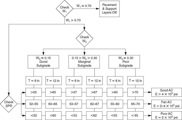
FIGURE 3.52 Evaluation of thick (thickness 8 to 12 in or 200 to 300 mm) flexible pavements from Dynaflect measurements. Conversion: 1 psi = 6.895 X 10⁻³ MPa. (From К. Majidzadeh and V. Kumar, Manual of Operation and Use of Dynaflect for Pavement Evaluation, Resource International, Inc., Columbus, Ohio, Report No. FHWA/OH-83/004, October 1983, with permission)


Подпись: 297

METHODS OF PAVEMENT REHABILITATION

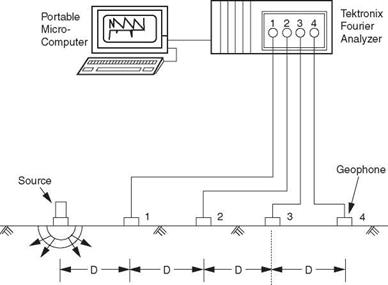
FIGURE 3.53 Schematic diagram of spectral analysis of surface waves (SASW) testing setup. (From S. Nazarian, D. Yuan, and M. R. Baker, Rapid Determination of Moduli with Spectral-Analysis-of-Surface-Waves Method, The University of Texas at El Paso, El Paso, Texas, Report No. TX-94 1243-1, November 1995, with permission)

design traffic. The disadvantage of this type of treatment is that, if the joints are not repaired properly, they will fail prematurely. Joint repair quantities are difficult to esti­mate, because joints continue to fail between the time the rehabilitation was designed and the time construction begins. The advantage of this type of treatment is that it utilizes the strength of existing pavement rather than an overlay, so overhead clearance problems are postponed or eliminated.

Repair and Overlay. When nondestructive testing measurements indicate that the existing slab thickness is insufficient to carry future design traffic, a common tech­nique is to repair failed joints or pavement and add an asphalt overlay. Generally, rigid repairs are preferred over flexible repairs. Flexible repairs in a rigid pavement do nothing to reestablish load transfer across the failed joint. Flexible repairs also have a tendency to heave because they are weak in compression and the rigid pavements expand during hot weather. Flexible repairs allow joints to open up beyond the design of the joint sealant, causing the joint sealant to fail. Finally, flexible repairs reduce pressure in a pavement and allow midpanel cracks to open up and lose aggregate inter­lock. The advantages of flexible repairs are the favorable cost and construction time. Disadvantages of rigid repairs include the construction complexity and time. It is important to realize that the biggest drawback of the repair and overlay strategy is the inability to estimate the amount of repair required at each pavement failure and, for jointed pavements, the number of joints that need repair. Designed overlays are usually thin (3 to 6 in or 75 to 150 mm). In cold climates, joints usually reflect through the overlay after one or two winters. Joint reflection cracking can be addressed by sawing and sealing a joint in the asphalt overlay at the exact same location as the joint in the underlying rigid pavement. Failure to align the flexible joint with the rigid joint will result in premature joint spalling of the asphalt layer.

Bonded Concrete Overlay. Another technique to increase pavement structural capacity is to bond additional concrete to the surface of the existing concrete pavement. The required overlay thickness is determined by subtracting the effective thickness, determined by nondestructive testing of the pavement, from the thickness required for a new pavement. Cracks in the underlying pavement will reflect through the overlay. Therefore, all joints and working cracks must be established in the overlay directly over joints and cracks in the existing pavement. For CRC pavement, this is generally not a concern. The existing pavement must be cleaned to ensure a proper bond. This technique is advised only for pavements that are in sound condition with little distress. Any areas showing deterioration must be repaired prior to the overlay.

Break and Seat for JRCP. The break and seat method for jointed reinforced concrete

pavement is accomplished by breaking the long slabs into shorter slabs to distribute the expansion and contraction movement of the pavement over more cracks or joints. This reduces the strains in the asphalt overlay over the cracks or joints to the point where reflective cracking is retarded. The smaller slabs are seated in the subgrade by rolling to reduce vertical deflections. The overlay is designed as a new flexible pave­ment section with the broken and seated pavement as a base. The broken and seated pavement is given a structural coefficient as determined by nondestructive testing. One disadvantage of this technique is that, to fail or debond the reinforcing steel, tremen­dous breaking effort is required, and this results in a weak and nonuniform base. Where the reinforcing steel is not failed or debonded, large slabs continue to behave as large slabs, causing the joints to reflect through the overlay. Additionally, breaking does not correct problems at joints. Failed joints continue to be weak points in the pavement and usually heave, creating a hump in the overlay. The advantage to this technique is that broken and seated pavements tend to require thick overlays and maintain a high level of serviceability. Additionally, reflective cracking is of low severity when compared with cracking in thin asphalt overlays.

Crack and Seat for JPCP. The crack and seat method for plain concrete pavement (nonreinforced) is accomplished by producing several transverse cracks in each slab, thus transforming the long slabs into shorter slabs to distribute the expansion and con­traction movement. This reduces the strains in the asphalt overlay over the joints to the point where reflective cracking is retarded, and the smaller slabs are seated in the subgrade to reduce vertical deflections. By definition, crack and seat produces a crack visible when the pavement is wetted with water. As with break and seat, the overlay is designed as a new flexible pavement section with the cracked and seated pavement as a base, and with a structural coefficient as determined by nondestructive testing. The disadvantage of this method is that the cracking does not correct problems at joints. Joints that have failed continue to be weak points in the pavement and usually heave, creating a hump in the overlay. The advantage of this method is that cracked and seated pavements with thick overlays (7 in or more) exhibit a high level of serviceability, and reflective cracking is of low severity when compared with cracking in thin asphalt overlays.

Rubblize and Roll. Rubblize and roll is applicable for all types of rigid pavement. This method is accomplished by breaking the existing pavement into 6 in (152 mm) size or less using a resonant beam breaker or multihead breaker. The rubblized concrete is compacted with a roller and used as a base for a new pavement. The overlay is designed as a new flexible pavement section with the rubblized and rolled pavement as a base. The rubblized pavement is given a structural coefficient based on nondestruc­tive testing. One disadvantage of this technique is that rubblizing weakens the pavement and thereby increases the required overlay thickness. Areas with soft subgrade require removal of the pavement and undercutting; otherwise, the rubblization process cannot be achieved properly. The geometry of the equipment prohibits breaking near portable barriers used for traffic control. Another disadvantage of this technique is that, because the resulting overlay is thick, elevation transitions at bridges require pavement replacement. One advantage of this technique is the complete utilization of the exist­ing pavement as a uniform base without discontinuities. For reinforced concrete pave­ment, the technique serves to completely debond the steel from the concrete.

Thick Asphalt Overlay with No Repairs. A thick asphalt overlay with no repairs is a quick and inexpensive rehabilitation strategy that can be used on any rigid pavement beyond eco­nomical repair. As the overlay thickness is increased, vertical deflection is decreased as a result of the increased structure. Horizontal movements in the slab are decreased because of lower temperature variations. This decreases the strain at the interface of the over­lay and pavement, which retards reflective cracking. The overlay is designed as a new flexible pavement section with the existing pavement as a base. The existing pavement is given a structural coefficient based on deflection testing. A disadvantage of this strategy is that problems at joints are not corrected. Joints that have failed continue to be weak points in the pavement. Another disadvantage is that the thick overlay neces­sitates pavement replacement to make elevation transitions at bridges. The advantages of this strategy are the low initial cost and ease of construction. Reflective cracking is of low severity when compared with cracking in thin asphalt overlays.

Unbonded Concrete Overlay. The purpose of breaking the bond between the old pavement and the proposed overlay is to separate the distresses in the old pavement from the new concrete overlay. Thus, the concrete overlay can be treated as a separate pavement, and the existing distressed pavement as a uniform base. There is little bene­fit derived from repairing the existing pavement prior to placing the overlay, as the bondbreaker will provide uniform support and interface for the concrete overlay. The bond – breaker is placed as a thin (1- to 3-in) asphalt overlay on the existing pavement, and the concrete overlay is placed on the bondbreaker. The thickness required for the concrete overlay can be determined using the following modified version of an equation developed by the Army Corps of Engineers:

T = V(RT)2 – (ET)2 (3.8)

where T = the required thickness of the concrete overlay, in (mm)

RT = required thickness of new concrete pavement on the existing subgrade and for the anticipated truck loading, in (mm); the existing subgrade strength can be determined from original construction and design records or from nondestructive testing

ET = effective thickness of existing concrete pavement as determined by non­destructive testing, in (mm)

This technique is most efficient if the entire width of the roadway is available for overlay at the same time, but this makes maintenance of traffic difficult. However, the strength of the existing pavement is utilized, and the performance can be expected to be similar to that of a new pavement.
Overview of SMA Design Methods

The basic and universal rules of stone matrix asphalt (SMA) design were described in the previous chapter. Chapter 7 provides an overview of SMA design methods devel­oped in various countries. Undoubtedly, there are many of them, so their description could be the subject of a separate book. We will focus here on the most distinctive or the most interesting ones available in the technical literature.

The literature about SMA design methods can be both instructive and creative. You may judge for yourself which method most closely fits your needs or seems to have the most merit.

7.1 GERMAN METHOD

7.1.1 Description of the Method

The German method is based on long-standing experience in the application of repeatable materials and mixes. Such an approach not only makes analyzing cases of successful and unsuccessful SMA much easier but also drawing conclusions and ultimately proposing changes to technical specifications.

It was discussed earlier that the recommended ratios of SMA ingredients (see Table 2.1), combined with precisely determined gradations of each aggregate frac­tion supplied by quarries, enable SMA design in principle almost without the use of boundary gradation curves. Obviously, such gradation curves are being published— the first one for SMA was ZTVbit-StB 84—and then widely applied in practice. The new ZTV Asphalt-StB 07 and TL Asphalt-StB 07 standards have been in use since 1st January 2009.

The following stages may be identified in the German method:

• Design composition of an aggregate mix according to gradation limits

• Determination of a series of binder contents in the mixture

• Preparation of Marshall samples (2 x 50 blows) for each variant of SMA mixture

• Determination of the volumetric parameters of the SMA specimens

• Selection of an optimum variant of the mixture meeting requirements

• Air voids in compacted asphalt samples at 2.5-3.0% (v/v)[27]

• Voids filled with binder

• Draindown testing with Schellenberg’s method

• Wheel-tracking (rutting) test (for selected types of SMA)

The content of the coarse aggregate fraction specified in ZTV Asphalt-StB 07 amounts to 70-80% (m/m) for SMA 8S and SMA 11S but only 60-70% (m/m) for SMA 5N.*

SIZING TABLES

Sizing tables are often used when sizing vent pipes (Fig. 5.21). There can be many different types of tables to use during a sizing procedure. For example,

lVa

’Л

lVi

Unlimited

lVi

V4

1V2

Unlimited

2

Vi

1 Vi

290

2

Vi

lVi

Unlimited

3

Vi

1V2

97

3

Vi

2

420

3

Vi

3

Unlimited

4

Vi

2

98

4

Vi

3

Unlimited

4

Vi

4

Unlimited

Drain pipe size (in)

Drain pipe size

(in/ft)

Vent pipe size (in)

Maximum developed length of vent pipe (ft)

FIGURE 5.21 ■ Vent sizing table for Zone Three (for use with individual, branch, and circuit vents for horizontal drain pipes). (Courtesy of McGraw-Hill)

Подпись: Wet-vented fixtures 1 to 2 Bathtubs or showers 3 to 5 Bathtubs or showers 6 to 9 Bathtubs or showers 10 to 16 Bathtubs or showers Подпись: Stack size required (inches) 2 2 Vi 3 4

you might use one table to size a vent stack (Fig. 5.22) and another table to size a wet stack vent (Fig. 5.23). Some codes might use one table for both types of vents (Fig. 5.24). Then you might have a different table to use when sizing branch vents or circuit vents (Fig. 5.25). Battery vents may require a dif­ferent table (Fig. 5.26). Once you have a sizing table to work with, sizing a vent system is not a complicated process.

FIGURE 5.22 ■ Sizing a vent stack for wet-venting in Zone Two. (Courtesy of McGraw-Hill)

Pipe size of stack (inches)

Fixture-unit load on stack

Maximum length of stack

2

4

30

3

24

50

4

50

100

6

100

300

FIGURE 5.23 ■ Sizing a wet stack vent in Zone Two. (Courtesy of McGraw-Hill)

Drain pipe size (inches)

Fixture-unit load on drain pipe

Vent pipe size (inches)

Maximum developed length of vent pipe (feet)

VA

8

VA

50

VA

8

VA

150

VA

10

VA

30

llA

10

VA

100

2

12

VA

75

2

12

2

200

2

20

VA

50

2

20

2

150

3

10

VA

42

3

10

2

150

3

10

3

1040

3

21

VA

32

3

21

2

110

3

21

3

810

3

102

VA

25

3

102

2

86

3

102

3

620

4

43

2

35

4

43

3

250

4

43

4

980

4

540

2

21

4

540

3

150

4

540

4

580

FIGURE 5.24 ■ Vent sizing for Zone Three (for use with vent stacks and stack vents). (Courtesy of McGraw-Hill)

Drain pipe size (inches)

Drain pipe grade per foot (inches)

Vent pipe size (inches)

Maximum developed length of vent pipe (feet)

1У2

Vi

I1/*

Unlimited

VA

%

ІУ2

Unlimited

2

lA

lVi

290

2

‘A

VA

Unlimited

3

Vi

VA

97

3

Vi

2

420

3

‘/4

3

Unlimited

4

Vi

2

98

4

‘/4

3

Unlimited

4

Vi

4

Unlimited

FIGURE 5.25 ■ Vent sizing for Zone Three (for use with individual, branch, and circuit vents for horizontal drain pipes. (Courtesy of McGraw-Hill)

WALL FRAMING ANATOMY

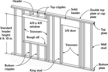
WALL FRAMING ANATOMYSTUDS are spaced on 16-in. or 24-in. centers. The length of the stud determines the overall height of the wall. Stan­dard stud length is 92% in.

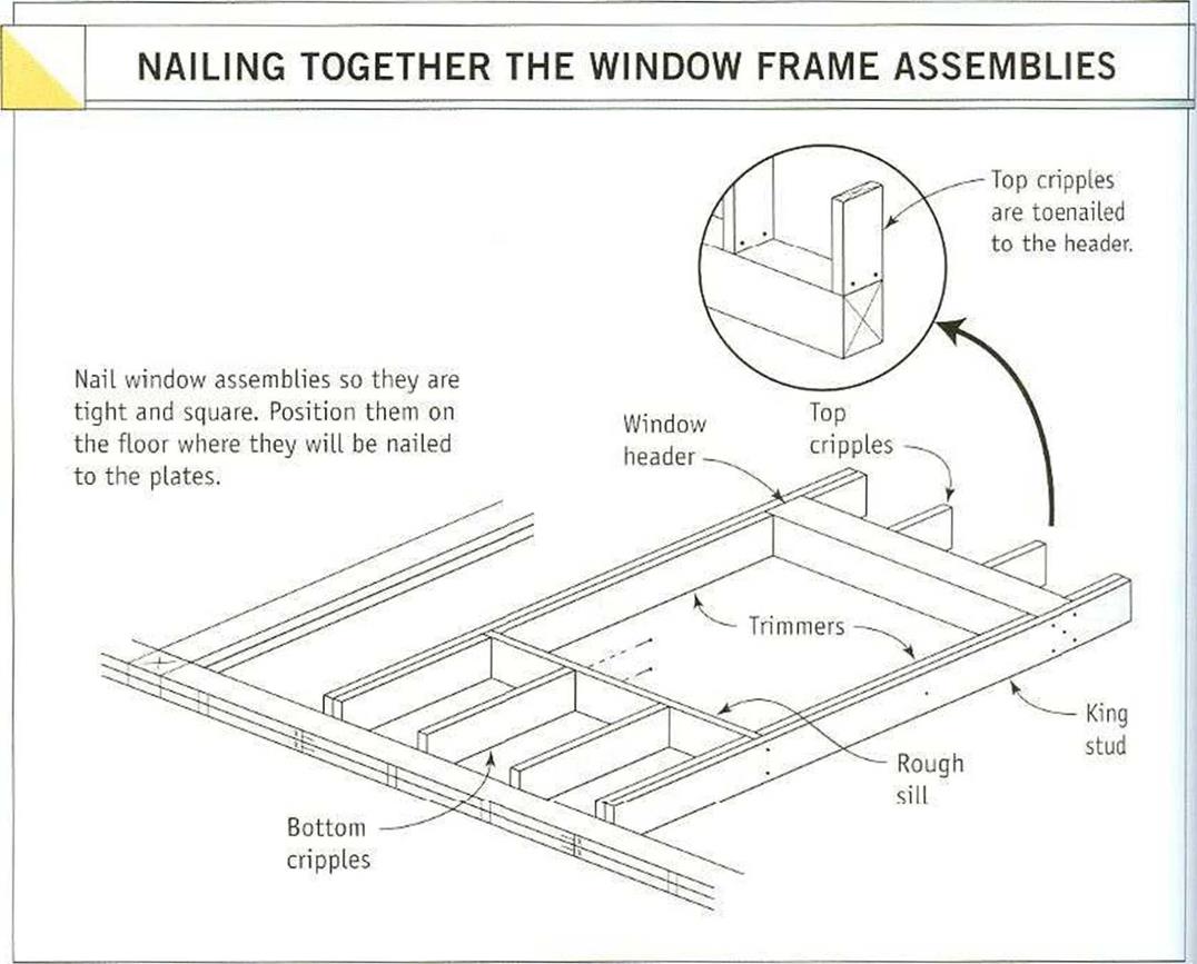
KING STUDS are full-length studs used on either side of a door or window opening. They back up trimmer studs and are nailed against the ends of the header and (for window openings) to rough sill.

TRIMMERS (also called trimmer studs) frame the sides of rough openings. They extend along king studs to support ends of headers.

CRIPPLES, often called jack studs, span the distance be­tween top plates and headers and between bottom plates and rough sills.

The BOTTOM PLATE is fastened to the floor deck or to a concrete slab floor.

The TOP PLATE is nailed to studs and cripples.

The DOUBLE TOP PLATE adds rigidity to the top of the wall and overlaps the top plate at wall intersections.

second is the height, and both are expressed in feet/inches. These dimensions are the actual door or window dimensions. To figure out your rough openings, you’ll have to add space for the jambs and trimmer studs. This is discussed in the following pages.

After you have a list of headers and all their dimensions for every opening in the house, you can cut and nail them together. Guidelines for sizing and building headers are explained in the sidebar on p. 84. If a door header requires cripples, mark their length on the header, then place the header along the plate where the doorway will be. On window headers, mark the length of the top and bottom cripples, then place each header near the plate location where it will be installed (see the photo at right).

Подпись: header height is 6 ft. 10//2 in.). Cut two trimmers for every window less than 8 ft. wide. For windows that are 8 ft. or wider, double up the trimmers on each side. Although you can cut door trimmers at this stage, I prefer to wait until the walls have been raised. The width of a rough window opening tells you how long to make the rough sill. Taking the Подпись: Label the grouped parts. Marked with the top and bottom cripple lengths, the rough sill for a window rests on the header. Both parts are placed on the wall plates where the window will be installed.Cut trimmers, rough sills, and cripples

Trimmers are cut and installed in pairs. The two trimmer studs set on the bottom plate support the ends of the header. Trimmers for 6/8 doors and windows are typically 801/2 in. long (81 in. in parts of the country where the

WALL FRAMING ANATOMY
Before the walls go up, we start with a bare floor deck and lots of lumber. Pretty soon there are 2x4s in all directions. Making cuts with a handsaw is no picnic, so be sure to have a good circular saw on hand.

Подпись: Laying out wall plates begins at the corners of the subfloor or slab. A piece of scrap that is the same width as the plates can be used to mark the corners quickly and accurately. Подпись: iiiiiiiiiiiiiiiiiiiiiiiiiiiiiiiiiiiiiiiiiiiiiiiiiiiiiiiiiiiiiiiiiiiiiiiiiПодпись: A chopsaw cuts parts quickly and accurately. To cut a number of framing members quickly and accurately, set up a chopsaw on a large work platform.

trimmers into account, the rough still for a win­dow is 3 in. shorter than the window header. A 36 in. window with a 39 in. header gets a 36 in. rough sill. Tack rough sills to the header with one 8d nail, and make sure that the sizes of the window and cripples are marked on the header or sill. For windows that are 6 ft. or wider, you’ll need to double up on the rough sills and shorten the cripples by 1 /6 in.

Cut the cripples after you have cut all the headers, trimmers, and rough sills. Use a story pole, and make sure that your head is clear and your mind is focused. Making a mistake in the cripple length can result in window frames not fitting inside their openings, but you may not know that until all the walls have been built and raised. I once cut all of a house’s top cripples 1 in. too long. As a result, I had to remove every door and window header and shorten all of the cripples. Not a good way to start the week.

Cut enough top and bottom cripples to nail one on each end of every header and rough sill and one every 16 in. or 24 in. o. c., depending on the stud spacing. A chopsaw set up on a good work platform is great for cutting cripples (see the photo at right). A stop block, secured to the worktable or to an extension attached to the chopsaw, will enable you to cut identical cripples quickly and precisely.