Important Considerations for Cutting Rafters

When cutting rafters, you need to consider the following four factors:

1. The length: determined by two factors— distance spanned and slope.

2. The adjustment to the length at the top and bottom. The top and bottom adjustments can depend on a number of factors and are almost always a little different. The two main factors are the distance from the true ridge or framing point, and the connection with other framing members.

3. The angle of cuts at the top, bottom, and the bird’s mouth. The angle cuts relate to the pitch of the roof and the position of the framing member the rafters are attaching to.

4. The height at the bird’s mouth. The height of the bird’s mouth can be set by details on the plans, for bearing, or to keep the roof level at the plate height.

There are many different ways to cut and set rafters. It doesn’t matter which method is used as long as the completed roof is structurally sound and looks the way it was intended. Different approaches work best on different types of roofs. Sometimes a combination of methods works best.

This chapter will not discuss the specifics of all the different rafter cutting methods, but will instead describe what is possibly the easiest way for figuring the information needed to cut rafters. Using this method, you will be able to “cut and stack" a roof. That is to say, you will be able to cut all the rafters on the ground and stack them ready for installation before the first one is installed.

Step 1-Find the Lengths of Common Rafters

There are six methods for finding common rafter lengths. Study them all and use the one that works best for you.

They are:

A. The Pythagorean Theorem

B. Framing Square Rafter Method

C. Framing Square Stepping Method

D. Chalking Lines Duplication Method

E. Computer Software Method

F. Diagonal Percent Method

Methods for Finding Common Rafters

A. Pythagorean Theorem

B. Framing Square Rafter Method

E. Computer Software Method

C. Framing-Square Stepping Method

„.і.

-”’VyS’®..

Pythagoras was an ancient Greek philosopher and mathematician. His famous theorem states that the square of the hypotenuse of a right triangle is equal to the sum of the squares of the two other sides. Thus: A2 + B2 = C2 In roof framing:

A = the Rise B = the Run

C (the hypotenuse) = the Rafter Length.

Run = У2 building width – У2 ridge board width H = is given on plans = the amount of rise per foot of run

Rafter Cut Length = Rafter Length + Rafter Tail Length

First, find the run by using this formula:

Run = У building width – У ridge board width

Second, find the rise by using this formula:

Rise = H/12 x Run

Third, find the rafter length by using this formula:
Rafter Length =/(Rise x Rise) + (Run x Run)

To apply this formula, multiply Rise x Rise, and then Run x Run. Add the two products, then press the square root key on your calculator. The result is the Rafter Length.

Finding Rafter Tail (T) Length

First, find the TRun by using the following formula: TRun = Overhang – Fascia

Second, find the TRise using the following formula:

TRise = H/12 x TRun

Third, find the Rafter Tail Length by using the following formula:

Rafter Tail Length =

/(TRise x TRise) + (TRun x TRun)

Note: Be sure to mark crowns on rafters prior to measuring and cutting. Crowns are always up.

Example: Finding Rafter Cut Length

12

Rafter Length: Let the pitch be 4 p and the building width be 20′ and the ridge board be Ш" thick.

Step 1: Run

= % (20′) – % (1%") = 9′-11/"

Step 2: Rise

= 4/12 x 9′-111/4"

= .3333 x 119.25" = 39.75 = 39%"

Step 3: Rafter Length

= У(119.25 x 119.25) + (39.75 x 39.75) = /14,220.56 + 1,580.06 = ч/15,800.62 = 125.70

= 125 11/16"

Rafter Tail Length: Let overhang be 2′ and fascia be Ш".

Step 1: TRun

= 2′ – 1%" = 1′-10%"

Step 2: TRise

= 4/12 x 1′-10%"

= .3333 x 22.5" = 7.49 = 7.49 = 7%"

Rafter Cut Length

= 125 11/16 + 2311/16 = 149 3/8"Step

Step 3: Rafter Tail Length

= /(7.49 x 7.49) + (22.5 x 22.5) =/56.10 + 506.25

= 562.35 = 23.71

= 23 11/16"

TRun = length of a horizontal line from the building’s exterior wall to the outermost point on the fascia (overhang distance). (See diagram on page 76.)

TRise = Amount of vertical rise in the length of TRun.

Steps

4. Find run of rafter and multiply by multiplication factor.

5. Subtract V2 thickness of ridge board to determine the rafter length.

Step 1 = 4 Step 2 = 4 Step 3 =

Step 4 =

Step 5 =

Rafter Tail Length for overhang is found using the same method as for the rafter length, except that Step 5 (subtraction for ridge board) is eliminated. The rafter tail length is then added to the rafter length to produce the rafter tail cut length.

The pitch of the roof is given on the plans in this

way: 12

6H

The number 12 is constant and indicates 12 inches of run, or horizontal distance. The other number represents the rise and varies, depending on how steep the roof is. In the example below, for every 12" of run, or horizontal distance, there is 6" of rise, or vertical distance. The greater this number, the steeper the roof.

To find the rafter length, first lay the framing square on the rafter at 12" on the blade and the

amount of rise on the tongue, 6". Once the framing square is set with stair nuts, just step off the amount of run along the rafter.

Example

Let the run equal 10′-4"

Let the overhang equal 1′-6"

1. Set framing square with stair nuts: the run 12" on the blade; the rise 6" on the tongue.

2. Step off 11′.

3. Perpendicular to the end lines, mark 4" (top), and 6" (bottom). Place the square at those marks to draw the plumb lines for the ridge and tail cuts.

The Space around the Chimney Needs a Fire-Resistant Seal

T

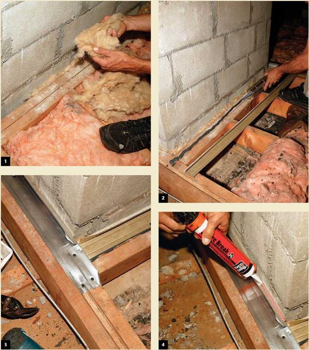
here’s usually a 2-in.-wide gap, required by code, between framing and masonry chimneys. To close the gap, I first stuff it with rockwool (1), then apply a bead of adhesive caulk to the framing (2). Next, I screw down wide strips of metal (recycled drip edge)
along the perimeter (3). I seal the metal to the chim­ney with fire-rated intumescent caulk (4). For continu­ity, you need to seal the ceiling joists to the drywall below and at inside/outside corners of the rough opening with expanding foam.

The Space around the Chimney Needs a Fire-Resistant Seal

The Physical Processes Contributing to Water-Induced Damage

The existence of a water flow through an asphaltic mixture may cause desorption of parts of the mastic films which are in direct contact with the water flow, Fig. 5.8(a) carrying away elements of the bitumen[8] by advection (see Chapter 6 for a fuller definition of advection). Exposure of an asphaltic mixture to stationary water (i. e. no

The Physical Processes Contributing to Water-Induced Damage

Fig. 5.8 Schematic of physical water damage-inducing processes (Kringos & Scarpas, 2005a; Kringos, 2007) (a) Loss of mastic due to advective transport (b) Damage of the bond due to water diffusion

water flow) would, therefore, show no advective transport damage. Since practice has shown that exposure of asphaltic mixtures to stationary water does, in time, cause ravelling of the mixture, this process cannot be the only phenomenon causing water damage. In asphaltic mixtures, diffusion of water through the mastic films surrounding the aggregates is a molecular process that may eventually lead to water reaching the interface area between the mastic and the aggregates. Depending on the bond characteristics, the water can then cause an adhesive failure of the mastic – aggregate interface, Fig. 5.8b).

The Physical Processes Contributing to Water-Induced Damage

Fig. 5.9 Simulation of loss of mastic from around a coarse aggregate particle due to a fast water flow field

Aggregate is omitted in Finite Element model shown in the lower part of the figure.

As time increases, the diffusion of water through the mastic weakens the cohesive strength and the stiffness of the mastic and may actually aggravate the desorption. These are modelled using the approaches set out in Chapter 11. More details about these mathematical formulations can be found in Kringos & Scarpas (2004; 2005a & 2006), Kringos (2007) and Kringos et al. (2007). Figure 5.9 shows an example of a mastic desorption simulation with RoAM, in which a coated aggregate is exposed to a fast water flow field.

Fog Sealing

A fog seal is an application of a diluted asphalt emulsion to a weathered asphalt surface. It is used to seal and enrich the surface, seal out moisture, close up hairline cracks, and prevent oxidation and raveling. Fog seals are generally restricted to low-volume, low-speed roadways and parking lots, as they have a tendency to cause loss of friction for a short period of time after application. Fog seals should only be used on suffi­ciently weathered pavements that have the ability to absorb the asphalt emulsion. Fog seals should be placed on dry, clean pavements, when temperatures are warm or hot. Traffic should be kept off the fog seal until the emulsion has cured. Up to 3 h may be necessary to ensure sufficient cure. Fog seals can be expected to last as long as 3 years.

3.10.1 Chip Sealing

Chip seal is a sprayed application of a polymer-modified asphalt binder covered immediately by a washed limestone, dolomite aggregate, or trap rock and rolled with a

pneumatic roller. The binder is applied by an approved bituminous distributor, and the aggregate placed by an approved aggregate spreader. The rolling operation is intended to seat the aggregate into the binder and ensure chip retention. Chip seals can be placed as single or double applications, depending on pavement condition. Chip seal is most generally applied to low-volume roadways, but has been applied to roadways with average daily traffic levels (ADTs) as high as 30,000. Chip seals are intended to pro­vide a new wearing surface as well as to eliminate raveling, retard oxidation, reduce the intrusion of water, improve surface friction, and seal cracks.

Chip seals should only be applied to pavements that are structurally sound and suit­able for preventive maintenance. The following conditions should be given careful consideration prior to a chip seal:

• Localized wheel track cracking should be repaired full depth.

• Any potholes must be repaired full depth.

• Areas which exhibit debonding must be patched partial depth.

• All existing patches must be in good repair prior to chip sealing.

• All existing cracks must be crack-sealed prior to chip sealing.

• Localized high-severity edge cracking must be repaired full depth (see Fig. 3.56) prior to a chip seal.

• Rutting must be no more than 1/8 in (3 mm) deep.

Traffic should be restricted and speeds reduced to minimize the loss of chips from the pavement surface. Length of time for traffic restrictions depends largely on ambient weather conditions at the time of construction of the chip seal. The construction season for this work is relatively short. Chip seals should not be placed in cool weather. It usually requires about 1 month of warm weather following construction for the aggregate

Fog Sealing

FIGURE 3.56 Localized edge cracking must be repaired full depth before chip sealing.

particles to become reoriented and properly embedded in the asphalt membrane. The expected service life of a chip seal is 5 to 7 years.

Crack Sealing

Crack sealing is the placement of a sealant into existing cracks of a pavement. The sealant is made of a mixture of a neat or modified asphalt cement binder, with a number of possible additives such as rubber, polyester or polypropylene fibers, or polymers. Crack sealing can be placed into routed crack reservoirs using backer rods (see Fig. 3.6) or can be placed directly over the crack using an overband technique. Crack sealing is used to minimize the intrusion of water into the pavement. By keeping water out of the pavement, erosion of the mix is kept to a minimum, deterioration of the crack is slowed, and less water is available to saturate the base materials.

There is a wide window of opportunity for cost-effective crack sealing of flexible or composite pavements. In general, cracks that display significant raveling of the crack face and secondary branch cracking (see Fig. 3.54) need more than just a crack seal and should be considered for some other type of preventive maintenance, which may include crack sealing.

Crack Sealing

FIGURE 3.54 Secondary cracking of asphalt surface.

Rigid pavements are not expected to have cracks wider than hairline. Crack sealing hairline cracks in a rigid pavement has not been shown to be cost effective (see Fig. 3.55), and will result in a noisier and rougher riding pavement. Where cracks are found to be wider than 1/8 in (3 mm) and less than 1/4 in (6 mm), crack sealing may be beneficial; however, further investigation is recommended, as more serious problems may be present.

Best practice is to select pavements that have sufficient cracking for crack sealing mobilization to be worthwhile, yet preclude excessively cracked pavements. Furthermore, pavements that require the use of crack sealing material in excess of 5000 lb/lane mile (1400 kg/lane km) are questionable candidates for crack sealing.

Crack Sealing

FIGURE 3.55 Hairline crack in rigid pavement.

TABLE 3.28 Rubber-Asphalt Joint Sealing Compound Quantities Needed for Different Depths and Widths of Openings

Pounds required per 100 lineal ft for indicated width of opening

in

К in

38 in

V-2 in

58 in

% in

78 in

1 in

34

8.3

12.4

16.5

20.6

24.8

28.9

33.0

78

9.6

14.4

19.3

25.0

28.9

33.7

38.5

1

11.0

16.5

22.0

27.5

33.0

38.5

44.0

1%

12.4

18.6

22.8

31.0

37.2

43.3

49.5

1%

13.8

20.7

27.5

34.4

41.3

48.1

55.0

138

15.2

23.8

30.3

37.8

45.4

52.9

60.5

118

16.5

24.8

33.0

41.3

49.5

57.8

66.0

158

17.9

26.8

35.8

44.7

53.6

63.5

72.5

134

19.3

28.9

38.5

48.1

57.8

67.4

77.0

178

20.6

30.9

41.3

52.5

61.9

73.2

82.5

2

22.0

33.0

44.0

55.0

66.0

77.0

88.0

Conversions: 1 in

= 25.4 mm,

1 ft = 0.305

m, 1 lb

= 0.454 kg.

Where crack sealing is not a suitable method of preventive maintenance, other forms of pavement preservation should be considered. Table 3.28 is provided for quantity esti­mation. The table is based on a unit material weight of 63 lb/ft3 (1000 kg/m3), and does not account for waste or spillage. This table is applicable for crack sealing materi­als meeting the requirements of ASTM D-6690.

Maintenance of traffic is required to apply the sealant and allow it to cure. Cure time is usually less than 1 h. Crack sealing operations are most effective when pavement temperatures are cool to cold. As pavements cool they contract, and thus widen the cracks, allowing more sealant to enter the pavement. Crack sealing should not be done on wet or damp pavements and should be applied on pavements when both surface temperature and ambient air temperature are above 40°F (4°C).

Crack sealing will have little effect on the current pavement condition. The intent of crack sealing is to slow the rate of deterioration and prolong pavement life. Crack sealants are expected to last 2 to 3 years before reapplication is necessary.

Skylight above a Flat Ceiling

Positioning a skylight above a flat ceiling is an inexact science. Situating the skylight between rafters is easy enough, but because lightwells flare out, sizing and positioning the ceiling opening can be tricky if you’ve never done it before. Here are a few tips to demystify and simplify the process.

► Use a pencil or painter’s tape to roughly outline the lightwell opening on the ceiling. Push nails up through the corners of the opening so you can spot them from above.

► Go into the attic or crawl space above to find the four corner nails and determine if there are wires, pipes, and ducts that would be a problem to relocate. Avoid positioning skylights where roof planes converge, by all means. It’s far easier to reposition the skylight.

► If the space over the ceiling is inaccessible, turn off the electricity and use

a cordless recip saw (or a hammer) to punch a hole big enough for your head, so you can take a better look before enlarging the hole.

► If you can position skylight openings to avoid cutting rafters or ceiling joists, do so. If you must cut more than one rafter, have an engineer review your plans. Otherwise, double up headers and trimmers around the rough opening(s) to redistrib­ute the loads, and use steel connectors to ensure solid connections.

► Flare the top and bottom of the lightwell but, if possible, leave the sides vertical. To simplify layout further, make the upper (end) wall of the lightwell perpendicular to the rafters and the lower (end) wall, plumb, as shown in "Skylight Positioning," at left. It’s possible to flare all four surfaces, but compound-angle cuts on all studs are a monster to do correctly.

► When you have a better sense of the lightwell’s location, enlarge the hole

in the ceiling but don’t cut it to its final size yet. To mark the corners of the opening in the roof, drive 16d nails up through the sheathing. Note: Thus far you’ve cut into finish surfaces only, not into framing.

After snapping chalklines to outline the rough opening, use a utility knife with a hooked blade to cut the shingles. Then use a shingle ripper (left) or a flat bar (right) to pry up the shingle nails and remove the shingles within the cutout area. Kneepads are a must for most roof work.


Unless you are highly skilled with a reciprocating saw, like this pro, use a circular saw to cut through the roof sheathing. To avoiding gumming up a blade, remove the building paper before cutting. Be sure to wear eye protection.


Standing outside the cutout area, pry up the sheathing and pass it through the hole to your helper inside. By the way, many old-timers don’t like sneakers because nails can pierce the thin soles; on the other hand, sneakers can improve your footing. Your call.


image258

After removing the sheathing, the installer used a hooked blade to cut back the shingles more precisely so the Velux skylight’s mounting brackets could sit on the flat plane of the roof sheathing, rather than on an uneven shingle surface.


Here, all four lightwell walls will flare out toward the bottom (none plumb). Using his level as a straightedge, the installer marks the rafter cuts; the level runs from the edge of the roof opening to the doubled headers in the ceiling opening. After cutting the rafters, he’ll attach a doubled header behind the cut-line.


image259

Подпись: PROnP Cut the Length of the light- well a little long. It's difficult to know exactly where the grooved lower edge of the skylight curb will meet the finish surface on the plumbed lower wall, so you're better off cutting the opening long and shimming it up as needed, using thin pieces of plywood. Ultimately, '/2-in. dry- wall edges should fit perfectly into curb grooves. llll

shingles within the RO without disturbing those around the perimeter.

Once you’ve removed the shingles within the RO, use a circular saw with demolition blade set to the depth of the roof sheathing. If you’re skilled, you can use a reciprocating saw with a bimetal blade to cut through the sheathing, as the pro is doing in the photo on p. 121, but don’t cut through a rafter while you’re standing on it! Whatever tool you use, wear eye protection because you’re likely to hit nails. After you’ve cut around the perimeter of the RO, use a claw ham­mer or a flat bar to pry out the sheathing.

Next slide a shingle ripper under the shingles around the RO, gently breaking the self-sealing shingle spots and pulling out any nails within 1 ft. of the opening. This nail-free perimeter will enable you to properly flash the skylight curb with building paper or self-adhering bituminous flashing. Finally, if you’re installing a skylight with L-shape mounting brackets, cut back the shingles an additional 1 h in. to 2 in. around the RO so the brackets can sit on a uniformly flat surface and be screwed easily into sheathing.

Framing. Frame the roof opening and the light – well. Before cutting through the rafters, install temporary braces to the ceiling joists below; those rafter braces stay in place till the rafters are head – ered off. If the upper wall of the lightwell will be perpendicular to the rafters, use a framing square to mark a square cut back 3 in. from the edge of the opening (a doubled header is 3 in. wide).

The lower end of the lightwell is a bit trickier to frame because it intersects the roof plane at an obtuse angle (greater than 90°). Hold a 4-ft. level plumb against the lower edge of the roof RO, and then mark that angle onto the face of the trimmer rafters on each side of the opening. Bevel-cut the top edges of the doubled headers at that same angle. Once you’ve headered off the top and bot­tom of the RO, double up the trimmer rafters along the sides of the opening, using as long a board as possible. (Space is tight in an attic.)

Finally, install studs running from the RO in the roof to the RO in the ceiling below. If you install the four corner studs first, you can run taut strings between them to align the interven­ing studs. If the lightwell sidewalls are plumb, rather than flared out, you will have saved your­self a lot of work.

Stage 3: Determining Air Voids in a Compacted Coarse Aggregate

The Americans have undertaken analyses on the usefulness of various methods of testing for contact between coarse particles. Ultimately, they have settled on the dry – rodded test according to AASHTO T 19-00 (Brown and Haddock, 1997). It has also been standardized as ASTM C29-97.

Let us remember what we are considering now; we are looking for the content of air voids among the compacted coarse particles that make a skeleton. Thus we are screening the coarse aggregate (regarded as the active fraction) of each of three trial aggregate mixes (three design gradation curves of Stage 2) through the boundary sieve (BP sieve) selected in accordance with the NMAS. Furthermore, three such screened samples of the coarse aggregate will be tested according to the dry-rodded method.

What does the dry-rodded method involve? All in all, it consists of compacting the coarse aggregate and determining the air voids among the particles. As a result, dry-rodded testing provides the percentage of air voids in a compacted skeleton of coarse aggregate denoted as VCAdrc. It should be remembered that Volume of coarse Aggregate-Dry Rodded condition (VCAdrc) has been determined for the part of an aggregate mix that is larger than the BP sieve for the size of SMA being designed.

And now the first stage of control in creating the skeleton is behind us.

PAVEMENT PREVENTIVE MAINTENANCE

Preventive maintenance (PM) is a cost-effective strategy of early maintenance done to a pavement as a preemptive measure to preserve the pavement by retarding deterioration. PM is traditionally a low-cost treatment done early in a pavement’s deterioration cycle. By definition, pavement preventive maintenance extends the service life and maintains or improves the functional condition of the system without substantially increasing struc­tural capacity.

Pavement PM treatments reduce the amount of water infiltrating the pavement structure and correct surface deficiencies such as roughness and non-load-related distress. These treatments contribute little or no improvement to the pavement structure. PM should never be applied if fatigue-related distress exists in the pavement.

If applied at the proper time, pavement PM will lower the life cycle cost of any given pavement section, and when applied on a network of pavements, will improve the system condition at a lower cost. Some of the more common pavement preventive maintenance treatments are discussed in Arts. 3.10.1 to 3.10.4.

Other fittings 9

In last article we got acquainted with a spring safety valve. It is possible to consider such design as the most vserasprostranenny, on the last measure, for introduction in a life. But without considering a spring drive other designs were extended also. Namely, the lever and cargo safety valve completely can meet. The scheme of that device is provided Continue reading

STEP5 Build the Walls

In addition to being a carpenter for the past 50 years, I’ve also been a gardener my entire life, and I see a lot of similarities between framing and gardening. If you take the time to prepare the ground, add lots of compost, plant good seeds, mulch well, and nurture young plants, you can’t help but grow out­standing vegetables. The situation is similar when you’re framing walls, if you take the time to lay out, cut, and correctly position every part of every wall, then the actual fram­ing will go smoothly and you’ll produce a quality building.

A Habitat volunteer once said to me, “Now the fun starts,” as we began to nail together all the wall pieces. I guess everything in life is rel alive. If you have to stand out in the blazing sun building walls day in and day out, the joy of framing does eventually wear off. On the

О «■

other hand, when working as a team, a group of people building walls will see a lot of progress in one day, and that is satisfying.

Before I start building walls, I a ways begin by cleaning up the work area. Some scrap will have been generated as you cut the parts for the walls and there’s no need to leave it lying around for someone to trip over.

Begin with door and window assemblies

1 begin framing by building the door and win­dow assemblies. All window headers and most door headers need top cripples (sometimes called jacks) and all rough sills need bottom cripples (see the illustration below). A chop – saw volunteer has probably already cut these to size, grouped them, and labeled them. Grab an armload and carry them to their proper locations. Check to see that the cripples match

Подпись:the lengths written on each header, livery header takes a cripple im each end and one on each layout mark. Pay close attention! Place bottom cripples perpendicular to the wall plates, exactly where they will be nailed in place. 1 also place a trimmer and a king stud next to each window opening before I do any nailing.

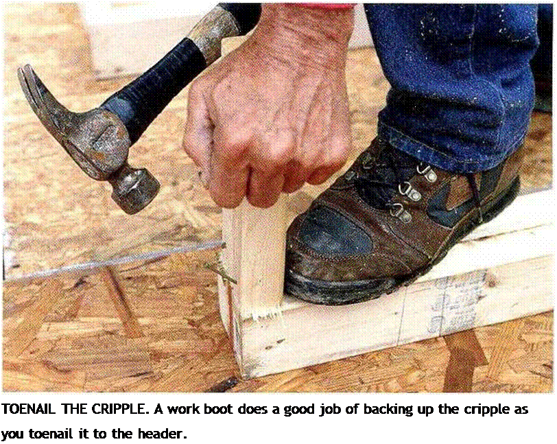
To make toenailing cripples to headers eas­ier, back up the cripple with your foot before starting the first two 8d toenails (see the photo at right). Make sure each 2x cripple is on its layout mark and flush with the sides of the header, then drive the nails home. After nailing off one side, toenail two more <8d nails into the other side. Repeat the process until all the top cripples for each wall have been nailed to their headers.

Attaching the bottom cripples to rough windowsills is easier. Move the rough sill to the upper ends of the cripples placed against the plates. There should be one cripple at each end of the sill and one at each layout mark. Drive two 16d nails about 4 in. from each edge of the rough sill into each cripple. When nailing near the end of 2xs, set the nail back from the end and drive it at an angle or blunt the nail point to reduce your chances of split­ting the board.

Finish the window-frame assemblies bv

/

nailing on the trimmers and king studs. This is easy to do now because y ou are working flat on the floor. Don’t move these units around. Keep them in place where they will be nailed to the plates. Nail the window trimmers flush with the ends of the bottom cripples. Secure the trimmers to the rough sill with just two 16dnails each. Then nail the king studs along­side them so they are flush with the top of the Hop cripples and with the bottom of the trim­mers. Secure the king studs on each side bv driving two 16d nails into a 2x header or four or five 16d nails into a larger header. Finally,

drive a nail near the top of the trimmer into the king stud. T he trimmers will be perma­nently nailed later, before you install the exte­rior sheathing or set the windows. As for door trimmers, wail to install them until after the walls have been raised.

Подпись: A FULL DECK OF DOOR AND WINDOW ASSEMBLIES. These assemblies are nailed together and ready to be installed between the top and bottom wall plates. [Photo Larry Наші.] With all the walls plated and the window and door frames nailed together, you’re ready to frame the walls. At tins stage, its smart to check vour work. Make sure that the framing members are flush with each other and nailed tightly together. Keep the door and window