REPOINTING MORTAR JOINTS

Even materials as durable as brick and mortar break down in time, most commonly near the top of a wall or chimney, where masonry is most exposed to the elements. Often, the struc­ture wasn’t capped or flashed properly. If the bricks are loose, remove them till you reach bricks that are solidly attached. If joints are weathered but bricks remain firmly attached, repoint (or tuck-point) the joints by partially cutting back the mortar, adding new mortar, and shaping the joints. If the brick is painted, see "Stripping Painted Brick,” on p. 191.

Finally, if vertical or diagonal cracks run through several courses, there may be under­lying structural problems, which must be corrected before repointing. In this case, consult a structural engineer.

Raking old mortar. For best results, rake out (scrape out) mortar joints in an inconspicuous area as a test, starting with the least destructive tool. If the mortar is soft enough, an old screw­driver may be all you need. But if the mortar is as hard as the brick, you’ll need to be patient. Cut

FOR RAKING MORTAR

Before you can repoint joints, you must rake (cut back) old mortar, preferably without damaging surrounding brick. You’ve got several options:

► TUCK-POINTING (PLUGGING) CHISELS are usually thinner than mortar joints. Used with a 2-lb. hand sledge, they’re slow but exact.

► ANGLE GRINDERS with an abrasive wheel cut quickly into old mortar, but they can easily damage soft brick and leave a ragged line.

► PNEUMATIC AIR CHISELS represent a good balance of speed and control, but you’ll need to special-order mortar-removal bits. Trow & Holden (Barre, VT) offers a set that includes Vin. and V4-in. cape chisels, a V4-in. swept cape chisel, and a 4-tooth ripper. Wear safety glasses and a respirator mask when cutting mortar.

Подпись: Use a tuck-pointing (or plugging) chisel to cut back eroded mortar before repointing joints. The tool's narrow blade fits easily into joints and so is unlikely to damage brick faces. Подпись: PROnP Though it may seem counterintuitive, start washing brick walls at the bottom and work up, keeping the whole wall wet as you progress. If the entire wall is wet, dirty water and diluted cleaners running down won't streak the cleaned sections, but dirty water and chemicals running over unwetted dirty sections will leave marks. Подпись: lllljoints 1 in. deep, and try to cut a square trough (not a V-groove) in the old mortar.

Once you’ve raked the joints to the correct depth, brush them out well, using a whisk broom or a wallpaperer’s brush, which you can also use to wet down the joints before adding fresh mortar. Remove debris with an air hose or a heavy-duty vacuum. Of course, wear safety glasses and a respirator mask for this work.

The mortar mix. Try to match the old mortar mix when repointing an older brick building. Before portland cement was widely used, mortar joints were usually a resilient mix of hydrated lime and sand, which compressed slightly as the bricks expanded during summer and expanded slightly as the bricks contracted during cool weather. Soft, lime-rich mortars also show auto­genous healing, an ability to self-repair hairline cracks caused by seasonal temperature shifts. Mortar joints with portland cement, on the other hand, are relatively hard and inflexible: As old bricks heat up, they have no room to expand, so they crack and spall (flake).

Although mortar analysis is the best way to match old mixes—historic preservation agencies can suggest mortar analysts—type О mortar (described earlier in this chapter) should be a close match for most old mortars. For this, mix 1 part portland cement, 2 parts hydrated lime, and 8 parts fine sand. The mix should be fairly stiff as mortar mixes go, keeping its shape when squeezed into a ball. If the mix becomes too stiff to work, periodically sprinkle on and stir in small amounts of water.

If you’re repointing only a section of a struc­ture, however, and don’t want it to stick out like a sore thumb, experiment with combinations of mortar dye, cement, sand, and lime, carefully labeling the proportions of each batch and allow­ing it dry for a month before committing to a recipe. Masonry supply houses stock such mate­rials; they also carry new bricks manufactured to look old, should you need to replace bricks as well.

Repointing technique. Using a spray bottle or a brush, dampen the newly cleaned-out joints before applying fresh mortar. There are two ways to fill joints with new mortar. If you’re repointing a relatively small area, use a brick­layer’s trowel as a palette for the mortar and a tuck-pointing trowel to push the mortar into the joint. (See the photo on p. 198.) Press the mor­tar firmly, so that it will stick.

Подпись: WORKING MORTAR INTO JOINTSПодпись: Option 1: Let your bricklayer's trowel serve as a palette as you scoop mortar from it with your smaller pointing trowel and press mortar into joints. Two trowels are useful when repointing old joints. Подпись: Option 2: Or you can use a grout bag if you've got a lot of joints to fill. But this is hard work: The bag is heavy, and you need to twist hard to force the mortar out a small opening—a bit like wringing water from a stone. Подпись: Here a bullhorn jointer compresses mortar joints. If you’re repointing a large area, use a grout bag to squeeze the mortar into the joint. A grout bag looks like the pastry bag used to dispense fancy icing onto cakes. You force the mortar out by twisting the canvas bag. But you’ll need strong

hands and forearms to twist the filled 5-lb. to 10-lb. bag. And you may need to thin the mix slightly so it will flow easily through the bag.

After using a grout bag, you’ll still need to tuck- point the mortar joints.

When the mortar has dried enough to retain the imprint of your thumb, tool the joints. In most cases, use a jointer that creates mortar joints the same shape as the old ones. Point the head joints first, then the bed joints. As you work, use a trowel to clean the mortar from the brick faces, but don’t disturb the mortar joints. Then wait 2 hours or 3 hours before using a stiff plastic-bristle brush to remove the mortar still stuck to the brick faces.

Estimation of Runoff by Peak Flow Equations

Where there are no or insufficient stream-gauging records available, peak-flow methods such as the “rational method” and the Natural Resources Conservation Service (NRCS) method may be used. The rational method is the most common procedure for determin­ing the quantity of flow for the design of minor hydraulic structures. Its use in the United States dates back to the late 1800s. One of the basic design assumptions for its use is that
the rainfall intensity is uniform throughout the watershed. This assumption limits its use to relatively small watershed areas (in the neighborhood of 200 to 300 acres, or 1 km2).

The rational method is based on the simple intensity-runoff equation

Q = KCiA (5.2)

where Q = design discharge, ft3/s (m3/s)

C = runoff coefficient

i = average rainfall intensity, in/h (mm/h) for selected frequency and duration equal to time of concentration A = drainage area, acres (km2)

K = 1.0 for U. S. Customary units (0.278 for SI units)

Подпись: C Подпись: CA + C2 A+~ A1 + A2 +■" Подпись: (5.3)

After precipitation falls to the earth, it either is infiltrated into the earth, is evaporated back into the atmosphere, is subjected to depression or detention storage, or becomes runoff. The runoff coefficient C in Eq. (5.2) depicts the percent of precipitation that will run off the ground from the storm. Representative values of C for undeveloped and developed areas, respectively, are given in Tables 5.1 and 5.2. Also, if the watershed is made up of various surfaces, a weighted average should be used for C. This may be determined for surfaces with coefficients C1, C2, etc., and areas A1, A2, etc., as follows:

The intensity value i in Eq. (5.2) is dependent upon the time of concentration of the storm and the frequency of the design storm selected. Once these two parameters are selected, the rainfall intensity may be determined from an intensity-duration-frequency (IDF) curve. Such curves, which are derived from an accumulation of rainfall data recorded over the years, are available from both local and regional public agencies. (See, for example, U. S. Weather Bureau Technical Paper No. 25, “Rainfall Intensity – Duration-Frequency Curves for Selected Stations in the U. S.”) A method for developing rainfall intensity curves and equations is shown in FHWA publication HEC 12, “Drainage of Highway Pavements.” A typical IDF curve is shown in Fig. 5.1.

Estimation of Runoff by Statistical Methods

Estimating the peak discharge for which highway drainage structures are to be designed is one of the most common problems and biggest challenges faced by the highway engineer. The problem may be separated into two categories: (1) watersheds for which historical runoff data are available, those with gauged sites, and (2) areas for which no data are available. Gauged sites lend themselves to analysis of runoff by statistical methods, whereas ungauged sites rely upon hydrologic equations based on the hydrologic and physiographic characteristics of the watershed.

The runoff data necessary to utilize statistical methods are available through the USGS, which is the primary collector of such data. Additional data sources are given in Chapter 3 of FHWA publication HDS 2 “Highway Hydrology.” Provided that suffi­cient data are available for a specific site, a statistical analysis may be made that will result in a reasonable determination of the peak discharge. Water Resources Council Bulletin 17B, 1981, suggested that a minimum of 10 years of historic data are necessary to make an accurate estimation based on statistical methods. The USGS has no specific time requirements for historical hydrologic data collection. In the past, however, the rec­ommended time period varied between 10 years for a 10-year design flood to 25 years for a 100-year design flood. HDS 2 should be referenced for different techniques avail­able for determining the inferences of population characteristics from statistics.

Data collection can be categorized and arranged in groups that lend themselves to statistical analysis. The common groupings are by magnitude of peak annual discharge, by time of occurrence, and by geographic location. Of the three, magnitude of peak annual discharge is the most useful in determining peak discharge. Time of occurrence is the most useful in trend analysis or determining the effects of changing land use on runoff. Grouping by geographic location is the most useful when looking at sites that
have insufficient flood data either because they are ungauged or because the historical time frame of the collected data is too short.

There are several standard frequency distributions that have been extensively studied in the statistical analysis of hydrologic data. Three of the most useful are (1) log-Pearson type III distribution, (2) lognormal distribution, and (3) Gumbel extreme value distrib­ution. The log-Pearson type III distribution is popular largely because the distribution very often fits the available data closely and it is flexible enough to be used with many other types of distributions. Because of this flexibility, the U. S. Water Resources Council has recommended that it be used by all governmental agencies as the standard distribution for flood frequency studies. The characteristics of the lognormal distribu­tion are the same as those of the classical normal or Gaussian mathematical distribution except that the flood flow at a specified frequency is replaced with its logarithm and has a positive skew. Positive skew means that the distribution is skewed toward the high flows or extreme values. The characteristics of the Gumbel extreme value distribution (also known as the double exponential distribution of extreme values) are that the mean flood occurs at the return period Tr of 2.33 years and that it has a positive skew.

If runoff data are unavailable for a specific watershed area, one method that may be used to determine the peak stream discharge is a regional flood-frequency analysis. By using historical runoff records from similar drainage basins in the immediate area, estimates of peak discharges may be developed. The USGS is continuously updating the methodology by which the agency performs regional flood-frequency analyses. Recent advances include the use of the “ordinary least squares” and “region of influence” methods for regionalizing historic stream flow data.

Подпись: Y Подпись: aXb1 Xbf Xb3 ••• Xb Подпись: (5.1)

The statistical distributions commonly used for regional flood-frequency analysis result in an equation of the general form:

where Y = dependent variable

a = intercept coefficient Xj, X2,…, Xn = independent variables b1, b2,…, bn = regression coefficients

In practice, the dependent variable is the estimated stream flow for a given return period. The intercept coefficient is a constant used to differentiate the regions used in the analysis and the required return periods. The independent variables are drainage basin characteris­tics such as drainage area, basin or channel slope, and types of land cover; meteorological characteristics such as annual rainfall; and channel characteristics such as cross-sectional area, active channel width and depth, and flood-plain width and depth.

It is important to note the limitations of regional flood-frequency analyses and the resulting regression equations. In general, independent variables should be determined using the same techniques as were used during the regression analyses. For example, if USGS 7.5-minute quadrangles were used to determine basin characteristics for the regression analysis, then basin characteristics should also be obtained from 7.5-minute quadrangles for peak discharge estimations.

Flood Frequency

There are two accepted alternatives for determining the design flood frequency at a specific site: (1) by policy and (2) by economic assessment. An example of an estab­lishment of a design flood frequency by policy is the Code of Federal Regulations, which specifies that the design flood for encroachment onto through lanes of interstate highways shall not be less than the 50-year discharge. Most state and local agencies have established guidelines for policy requirements of design flood frequencies. For example, whereas bridges are designed to convey a 50-year discharge with a specified freeboard and to convey the 100-year discharge with no freeboard, California has adopted the policy that culverts may be designed for a 10-year flood without headwa­ter or to convey the base flood without damage to the facility or adjacent property. The base flood is defined as the flood or tide having a 1 percent chance of being exceeded in any given year, which is also defined as the 100-year flood. A design flood is a flood that will not inundate the highway—that is, will not cause the through lanes to be overtopped. An overtopping flood is a flood that will overtop the roadway, culvert, or bridge.

Blind adherence to the policy guideline to determine the design storm should be avoided. As a minimum, a range of peak flows should be considered and their poten­tial effects on the traveling public, the potential damage to upstream and downstream properties, and the possibility of loss of life should be analyzed. This preliminary assessment will indicate whether the policy determination for the design flood fre­quency was applicable or whether further analysis is required. Additional studies could take the form of providing the greatest flood hazard avoidance at the least total expected cost, as recommended in Federal Highway Administration (FHWA) Hydraulic Design Series (HDS) 6, “River Engineering for Highway Encroachments.”

. . Spreading the trusses

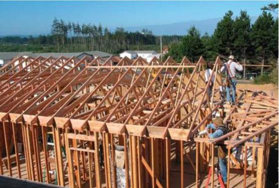
The temporary catwalk allows you to take a truss from a bundle and move it across the walls. Pull each truss, peak first, and spread it out near its layout mark. Each truss overlaps the previous one like a fallen domino.

STEP 2 INSTALL THE GABLE TRUSS

The first truss to be installed is the gable truss (also called an end truss or a rake truss) that rests on the top plate of an end wall. This truss is usually built differently from regular trusses. Instead of having angled web pieces, these end

. . Spreading the trussesRolling roof trusses. The first truss you should nail in place is the one for the gable end. Then it’s just a matter of rolling the remaining trusses in place, setting them on their layout marks, and nailing them down. You can do this while standing on the walls or by working off a ladder. [Photo by Don Charles Blom, courtesy Fine Homebuild­ing magazine © The Taunton Press, Inc.]

Подпись: Making gable-end notches. Whether you're installing trusses (see the photo below) or traditional rafters and ridge boards (see the photo above), the gable-end rafters require notches every 4 ft. to hold the lookout boards that support the barge rafter. Each lookout butts against the face of the closest inboard rafter, where it's nailed fast. [Top photo © Larry Haun; bottom photo © Roger Turk] . . Spreading the trusses

trusses often have vertical webbing spaced 16 in. or 24 in. o. c. to allow for easy installation of sheathing or siding.

Some carpenters like to sheathe end trusses with OSB and even finish siding before raising them upright. Another option is to cut all the sheathing pieces on the ground, raise the truss, and then nail the precut sheathing in place. It is certainly easier to sheathe a truss on the ground, but it makes the truss substantially heavier and more difficult, even dangerous, to handle. If you do decide to sheathe the trusses before raising them, let the sheathing lap down below the ceiling joist chord by a couple of inches. The lap will be nailed to the top plates once the gable is raised upright. This helps ensure a strong union between the truss and the wall, which is especially important in windy areas.

Notch the gable-end truss

Notches for lookouts are exceptions to the “never cut a truss” rule. Lookouts hold the barge rafters, which extend beyond the building line at each gable end to create a roof overhang (see the photos at right). Gable trusses are not self-supporting. They can be notched because they are nailed directly over a load-bearing wall. As a result, the entire joist chord of each a gable-end truss is fully supported.

It’s best to cut notches for 2×4 lookouts while the gable truss is still lying flat. For the first lookout, measure and mark 48 in. from the end of the truss tail. Cut a 2×4 notch (which is actu­ally ІУ2 in. deep and ЗУ2 in. wide) below the first 48-in. mark and every 48 in. thereafter (see the illustration on p. 121). With the gutter board or fascia in place, 4-ft.-wide sheathing will fall on the lookouts.

CHOOSING NOT TO NOTCH. Some houses (especially in northern areas) are designed without gable-end overhangs so that more sunlight can get into the house. If this is how you plan to build a house, lookouts or notches are not necessary. Instead, furr out the rake board with 1 x lumber, so that the exterior siding tucks under it (see the illustration on p. 120).

Weatherstripping

Подпись: INSULATION■ BY MATTHEW TEAGUE

Подпись: Durability: Good Cost: 50Ф/П. to about $2/ft. Weatherstripping

Weatherstripping

O

ver time, houses settle, doors sag, and weatherstripping wears out, creating small cracks around windows and doors. These leaks can account for 20% to 40% of a home’s heat loss. As warm air escapes in winter (and cool air in summer), the good money you’ve paid for heating (or air­conditioning) disappears, too.

Various contractors can bring in high – tech detectors to determine where your house is losing heat, but doing a close in­spection on your own reveals more trouble spots than you might imagine. Adding or replacing weatherstripping around windows and doors as well as sealing door bottoms are the obvious remedies to start with.

Many types of weatherstripping are avail­able at your local home center or hardware store. You can install several products easily without specialized tools; others are more difficult to install but can give you much longer service. This survey covers the range of weatherstripping products you’re likely to find at a local home center and provides you with the information you need to weigh cost, life expectancy, insulating efficiency, and installation effort.

Rigid Jamb

This type of weatherstripping consists of a metal or vinyl flange attached to a tubular section of either hollow vinyl or rubber. Tu­bular sections on higher-quality versions are filled with silicone or foam, which provides better insulation and allows the weather­stripping to hold its shape over time.

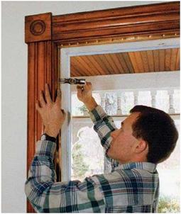
The flange is nailed, stapled, or screwed to the jamb, and the tubular section compresses to seal the open­ings. This product can be installed on either doors or windows: Simply close the window or door, butt the tubular section against it, and at­tach the flange to the jamb. Choose rigid-jamb styles that are adjustable; they usually have elongated holes for fasteners. Don’t paint the tubular sections because that reduces their flexibility and efficiency.

Подпись: Durability: Nail-on V-strips: good Adhesive V-strips: good Cost: $1/ft. to $2/ft. WeatherstrippingПодпись: Durability: Poor Cost: about ІЗФ/ft.WeatherstrippingWeatherstrippingVinyl

V-Strips

Sold in rolls, this flexible V-shaped weather­stripping compresses to seal gaps inside the tracks on windows and doors. V-strips come in bronze, vinyl, stainless steel, copper, and aluminum. One advantage of V-strips is that they disappear into the tracks of windows and doors. Adhesive-backed V-strips are the easiest to install.

Metal V-strips hold up better than the vinyl versions but are trickier to install. The ends of mating pieces must be cut (using tin snips) for a tight fit, and driving brads every 3 in. amounts to a lot of hammering. (Use a nailset for the last taps on the brads.) To prevent the leaves from overlapping at the corners, trim the leaves at an angle. Metal V-strips are quite durable; as they age and compress, run a putty knife, nailset, or screwdriver down the inside of the crease to extend their life.

One caveat: If doors and windows al­ready fit tightly, adding springy V-strips in the tracks will make them harder to open and close. On both windows and doors, you need to trim away parts of the weather­stripping to accommodate locks and pulley mechanisms.

Felt

Felt weatherstripping can be purchased in rolls of various thicknesses, widths, and colors. It comes in either pressure – sensitive or nail-on versions; some are adhered to a flexible vinyl or metal backing. The increased rigidity of the metal (or, to a lesser extent, vinyl) improves felt’s efficiency.

Wool felt is the most durable. However, because
felt can snag on splinters or catch between sliding parts, it tends to wear out quickly on operable windows and doors. In areas prone to moisture, avoid using felt altogether. Although it’s easy to install (and was the standard 50 years ago), felt is relatively inef­ficient compared to other weatherstripping products now on the market.

Roof Sheathing

Roof sheathing is placed on top of roof fram­ing members and under the roofing. As with exterior sheathing, exterior-grade plywood or OSB is most commonly used for this purpose. Unlike wall sheathing, roof sheathing will be exposed to high temperatures and will there­fore be subject to more intense outgassing. Roof sheathing usually has less time to air out in place since it is roofed over as soon as possi­ble to avoid water damage from precipitation. We therefore recommend that plywood, if used, be stickered and aired on site. We do not recommend OSB because it can develop mold and deteriorate more rapidly if it happens to get wet. When roofing members are exposed to the interior, as is often the case when beams or vigas are used, solid wood or tongue-and – groove planking is commonly used.

For sloped roofing, when structural condi­tions permit, purlins or skip sheathing maybe acceptable in place of solid sheathing. Purlins are wooden members spaced to receive metal roof panels, while skip sheathing consists of solid wooden members spaced more closely together for shingle and tile roof applications. Both purlins and skip sheathing eliminate the need for sheet goods and allow ample air movement to ventilate the roof space. How­ever, they do not provide the shear strength that plywood provides and their use must also be weighed from an engineering standpoint.

Roof Sheathing
Roof Sheathing

Where a continuous air barrier is installed be­tween the framing members and the living space, the choice of sheathing material is less crucial.

Consider the following guidelines for in­clusion in your specifications:

шяшшшшяшяшшяшяшяавяяшшшшяяшяшшI

• The use of solid wood boards, tongue – and-groove board, solid wood skip sheathing, or purlins is preferred where structurally acceptable.

• CDX-grade plywood, when used for roof sheathing, should be purchased as far in advance as possible to allow time to air
out. Provide protection against moisture damage.

• Provide a continuous air barrier on the inside face of the ceiling assembly as out­lined in Division 7.

CREATING EXTERIOR SOFFITS

In the dry Southwest, open, exposed rafter tails are preferred. But elsewhere—especially in cold, wet locations—soffits are more popular. Eave soffits are usually vented.

There are quite a few ways to frame soffits. The easiest way is to have the truss company extend the joist chord beyond the building line to form a level overhang. This is called a raised-heel truss.

If the trusses do not have a raised heel, you can still build a sof­fit easily by sheathing the underside of the sloped rafter tails. For a level soffit, nail a long 2x to the building and sheath between it and the gutter board or subfascia. If only a fascia board is used, cut a groove near the bottom edge to support the outer edge of the soffit board. No matter which type of fascia treatment you choose, make sure you install fire-stops between the studs to help prevent a fire in the wall from spreading into the soffit area. Check with your building department to find out which fire-stop details are required.

exterior walls and mark the entire length of the building at 2 ft., 4 ft., 6 ft., and so on, putting an “X” on the far side of each mark. Do the same on any long interior walls that run parallel to the outside walls. Mark the same 2-ft. o. c. layout on several straight 16-ft. 1×4 boards. These 1xs will later be nailed near the ridge to hold each truss upright at the proper spacing.

Despite your best efforts to line the walls (as explained in Chapter 4), the exterior eave wall plates may not be totally straight. If you hold the truss overhang to a wall that is not straight, the rafter ends and fascia won’t be straight, either. There is an easy way to remedy this. Measure 1 in. in from the outside at each end of the exterior wall’s top plate. Snap a chalkline the full length of the wall to create a straight reference line. Make an alignment mark on the joist chord of each truss. Measure in from the end of the truss the planned eave overhang distance plus 1 in. When install­ing each truss, put the truss mark right on the plate’s snapped reference line. As long as the truss fabricators cut all the tails the same length, the truss ends will be aligned.


WITH A RAISED-HEEL TRUSS


-Roof

sheathing


With a raised-heel truss, th e joist chords provide the framing for the eave soffit.


Rafter chord


Fascia
Soffit vent


Joist chord Exterior wall —


Soffit sheathing


Wall sheathing

WITHOUT A RAISED-HEEL TRUSS


CREATING EXTERIOR SOFFITS

Subfascia


A groove in the fasciai supports soffit board.


CREATING EXTERIOR SOFFITS

2x – nailer


Fire-stop


CREATING EXTERIOR SOFFITSCREATING EXTERIOR SOFFITSCREATING EXTERIOR SOFFITS

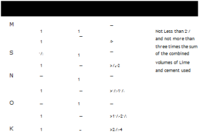
Mortar Types (ASTM C 270-68)*,t

Подпись: TYPE PORTLAND CEMENT MASONRY CEMENT HYDRATED LIME or LIME PUTTY AGGREGATE* M 1 1 — Not Less than 21/ 1 — fir and not more than three times the sum S 1/2 1 — of the combined 1 — >/4-2 volumes of Lime and cement used N — 1 — 1 — >1/2-11/4 O — 1 — 1 — >11/4-21/2 K 1 — >21/2-4 Подпись: Adapted from the publications of the American Society for Testing and Materials, as are the compression figures given in the text. t Parts by volume. t Measured in a damp, loose condition. TWO WAYS TO CUT BRICK

image381

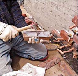
Using a mason’s hammer, score all the way around the brick, then strike the scored lines sharply.

Such cuts will be more accurate if you place the bricks on a bed of sand.

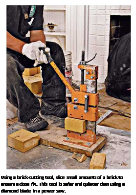
Подпись: Using a brick-cutting tool, slice small amounts of a brick to ensure a close fit. This tool is safer and quieter than using a diamond blade in a power saw.

Mortar will remain usable for about 2 hours, so mix only about two buckets at a time. If the batch seems to be drying out, “temper” it by sprinkling a little water on the batch and turning it over a few times with a trowel. As you seat each course of bricks in mortar, use the trowel to gen­tly scrape excess mortar from joints and throw it back into the pan or onto the mortarboard. Periodically turn that mortar back into the batch so it doesn’t dry out. Don’t reuse mortar that drops on the ground.

Trowel techniques. Hold a trowel with your thumb on top of the handle—not on the shank or the blade. This position keeps your thumb out of the mortar, while giving you control. Wrap your other fingers around the handle in a relaxed manner.

There are two basic ways to load a trowel with mortar. The first is to make two passes: Imagine that your mortar pan is the face of a clock. With the right-hand edge of the trowel raised slightly, take a pass through the mortar from 6:30 to 12:00. Make the second pass with the left-hand side of the blade tipped up slightly, traveling from 5:30 to 12:00. According to master mason and author Dick Kreh, a trowelful of mortar should

I Throwing Mortar

image383

As you turn the trowel to unload the mortar, pull it toward you quickly, thus stringing the mortar in a line.

resemble "a long church steeple, not a wide wedge of pie.”

The second method is to hold the trowel blade at an angle of about 80° to the mortarboard. Separate a portion of mortar from the main pile and, with the underside of the trowel blade, com­press the portion slightly, making a long, tapered shape. To lift the mortar from the board, put the trowel (blade face up) next to the mortar, with the blade edge farthest away slightly off the board. With a quick twist of the wrist, scoop up the mortar. This motion is a bit tricky: If the mor­tar is too wet, it will slide off.

To unload the mortar, twist your wrist 90° as you pull the trowel toward you. This motion spreads, or strings, the mortar in a straight line.

It is a quick motion, at once dumping and string­ing out the mortar, and it takes practice to mas­ter. If you are laying brick, practice throwing mortar along the face of a 2×4, which is about the same width as a wythe of brick. Each brick course gets a bed of mortar as wide as the wythe.

After you’ve strung out the mortar, furrow it lightly with the point of the trowel to spread the mortar evenly. Trim off the excess mortar that hangs outside the wythe, and begin laying brick.

Laying brick. If the first course is at floor level (rather than midway up a wall), snap a chalkline to establish a baseline. Otherwise, align new bricks to existing courses.

Throw and furrow a bed of mortar long enough to seat two or three bricks. If you’re fill­ing in an opening, "butter” the end of the first brick, to create a head joint, as shown in the bot­tom left photo at right. Press the brick into posi­tion and trim away excess mortar that squeezes out. Both bed and head joints are ’/2 in. to 58 in. thick until the brick is pressed into place, with a goal of compressing the joint to about 58 in. thick.

Use both hands as you work: One hand maneuvers the bricks, while the other works the trowel, scooping and applying mortar and tap­ping bricks in place with the trowel handle. If you use a stringline to align bricks, get your thumb out of the way of the string just as you put the brick into the mortar bed. As you place a brick next to one already in place, let your hand rest on both bricks; this gives you a quick indica­tion of level.

When you have laid about six bricks in a course, check for level. Leaving the level atop the course, use the edge of the trowel blade to tap high bricks down—tap the bricks, not the level. Tap as near the center of the bricks as the level will allow. If a brick is too low because you have scrimped on mortar, it’s best to remove it and reapply the mortar.

Next plumb the bricks, holding the level lightly against the bricks’ edges. Using the handle of the trowel, tap bricks till their edges are plumb. (Hold the level lightly against the brick, but avoid push­ing the level against the face of the brick.) Finally, use the trowel handle to tap bricks forward or back so that they align with a mason’s line or a level held lightly across the face of the structure

The last brick in a course is called the closure brick. Butter both ends of that brick liberally and slide it in place. The bed of mortar should also be generous. As you tap the brick into place with the trowel handle, scrape excess mortar off, ensuring a tight fit. If you scrimp on the mortar, you may need to pull the brick out and remortar it, per­haps disturbing bricks nearby.

Striking joints. Striking the mortar joints, also called tooling the joints, compresses and shapes the mortar. Typically, a mason will strike joints every two or three courses, before the mortar dries too much. To test the mortar’s readiness for striking, press your finger into it. If the indenta­tion stays, it’s ready to strike. If the mortar’s not reading for striking, wet mortar will cling to your finger and won’t stay indented.

Use a jointer to strike joints. First strike the head joints and then the bed joints. The shape of the joint determines how well it sheds water. As suggested in "Mortar Joints,” joints that shed water best include concave (the most common), V-shaped, and weathered joints. Flush joints are only fair at shedding water. Struck, raked, and extruded joints shed poorly because they have shelves on which water collects.

image386

Experienced masons lay up bricks from the corners in, moving string guides up as they complete each course.


image387

Before the mortar is compressed, it is ’/> in. to 5/8 in. thick, as shown. Press the brick into the mortar to create a good bond, compressing the mortar to 3/8 in. thick.


image384

Flush


ill

"V"


image385

Raked and tooled


C

Extruded


7

Struck


image388

Weathered


After using a bricklayer’s trowel to throw and furrow a mortar bed, butter one end of the brick to create a head joint.


After using the end of the trowel handle to tap the brick down, trim off the excess mortar.


Concave


image389

Mortar Types (ASTM C 270-68)*,t

Подпись: After the mortar joints have set enough to retain a thumbprint, strike (tool) them to compress the mortar and improve weatherability. Strike the head joints, as shown, before striking the bed joints. (This tool is a convex jointer.)

Mortar Types

Mortar is usually classified according to its strength and weatherability: The table at right describes the correct proportions of ingredients for each.

► Type M has the highest compressive strength, at least 2,500 pounds per square inch (psi). This durable mix is recommended for load-bearing walls, masonry below grade, and masonry that is not reinforced with steel.

► Type S has a relatively high compressive strength (1,800 psi) and the best tensile strength of any mortar listed here; so it best resists wind and soil movement.

► Type N offers medium compressive strength (800 psi) and is suitable for all above-grade uses, including those subject to heavy weathering, such as chimney mortar.

► Type O has a low compressive strength (325 psi) and is limited to non-load-bearing, interior uses. However, it is sometimes specified for repointing chimneys with soft, old brick that would be destroyed by stronger mortar (see "The mortar mix," on p. 190, for more information).

► Type K is an extremely low strength (100 psi) mortar and is not recommended.

Of the mortar types listed here, type N is the most versatile. A simplified version of its pro­portions is 1 part portland cement, 1 part lime, and 6 parts sand (or 1 part masonry cement and 3 parts sand). Before portland cement became widely used in the nineteenth century, mortar was usually a mixture of lime and sand (animal hair was often added to reduce cracking). If brickwork 100 years old or older needs repoint­ing, use type O so it won’t destroy the brick (roughly, 1 part portland cement, 2 parts lime, and 4 parts fine sand).

Dry mixing. When mixing mortar, mix the ingre­dients dry first to ensure a uniform mixture. That done, create a pocket in the middle, and add water gradually. As you add water, be fastidious about turning out the material in the corner of the mixing pan, so that there will be no dry spots. Mortar should be moist, yet stiff. A batch that’s too wet will produce a weak bond. Once the mix is nearly right, its texture will change radically if you add even a small amount of water.