Mark truss locations

Before trusses arrive on the job site, take some time to lay out their locations on the top of the wall plates. Hook a long tape on the end of the exterior walls and mark the entire length of the building at 2 ft., 4 ft., 6 ft., and so on, putting an "X" on the far side of each mark.

Do the same on any long interior walls that run parallel to the outside walls. Mark the same 2-ft. o. c. layout on several straight 16-ft. 1x4boards. These lxs will later be nailed near the ridge to hold each truss upright at the proper spacing.

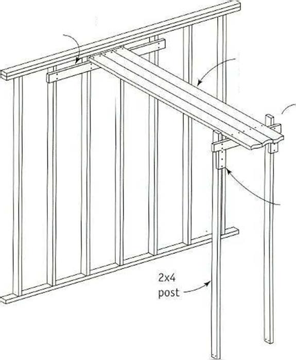
Подпись: BUILDING A CATWALKПодпись: Nail 2x4 cleat across four studs, 2 in. down from top plate.Подпись: 2x4 support block Support catwalk every 6 ft. Toe-nail supports to floor. Nail all cleats and support blocks securely. Подпись: To work on roof framing above a large room, you may need to construct a catwalk. At a wall near the center of the room, securely nail a 2x deal with 16d nails across four studs about 2 in. down from the top plate. Install a similar cleat on the opposite wall. Build a sturdy 2x support every 6 ft. Lay two or three 2x6 boards flat on this cleat and support and nail them in place.Mark truss locationsПодпись:Despite your best efforts to line the walls (asexplained in chapter 4), the exterior eave wall plates may not be totally straight. If you hold the truss overhang to a wall that is not straight, the rafter ends and fascia won’t be straight, either. There is an easv wav to remedy this. Measure 1 in. in from the outside at each

Подпись: «

end of the exterior wall’s top plate. Snap a chalkline the lull length of the wall to create a straight reference line. Make an alignment mark on the joist chord of each truss. Measure in from the end of the truss the planned eave overhang distance plus 1 in. When installing each truss, put the truss mark right on the plate’s snapped reference line. This guarantees that the truss ends are aligned.

General Considerations

The most common materials used are concrete, steel, aluminum, and plastic. The material used may affect the hydraulic capacity of the culvert, as different materials and wall configurations have different entrance loss coefficients and coefficients of roughness. The choice of the material is often controlled by structural and durability considerations.

The inlet configuration generally has a direct effect on the hydraulic capacity of the cul­vert and the backwater upstream from the site. The natural channel approaching the culvert is usually wider than the culvert, and thus the inlet operates as a flow contraction and can be the control for determining the hydraulic capacity. In many instances, the culvert is designed to operate hydraulically with the inlet submerged. This is one advantage that cul­verts have over bridges, which are designed for freeboard between the high-water elevation and the soffit. If the inlet provides for a gradual transition from the wider natural channel to the narrower culvert barrel, energy losses can be limited. Figure 5.11 depicts some com­mon transitions used to improve culvert hydraulics. Some of the common end treatments used at inlets and outlets include projecting ends, mitered ends, flared ends, and headwalls and wingwalls.

Projecting ends exist when the barrel of the culvert extends out from the face of the embankment. This is probably the least expensive but most hydraulically inefficient of the listed end treatments. It is unsightly, is potentially hazardous to traffic, and can induce scour damage. For these reasons its use should be limited to smaller culverts.

General Considerations

Подпись: 390

(b)

FIGURE5.il (Continued)


General ConsiderationsGeneral ConsiderationsGeneral ConsiderationsGeneral Considerations

Mitered ends exist where the culvert is formed or manufactured to be in the same plane as the embankment. Mitered ends, when compared with projected ends, are more aesthetically pleasing. However, the projected end is structurally more stable and the mitered end may require the addition of a headwall to compensate for this instability. The hydraulic efficiency of both the mitered and the projected inlets is approximately the same.

Flared ends are generally precast or prefabricated for use with concrete, corrugated steel or aluminum, and plastic pipes. They are used to retain the earth embankment and provide a hydraulic efficiency comparable to that of a headwall.

Headwalls and wingwalls are usually cast-in-place structures. They are designed to retain the embankment, improve hydraulics, prevent erosion, and, in larger-diameter flexible structures, provide support at the inlet and outlet ends. Retaining the earth has an economic benefit for larger structures in that the culvert may be shortened, thereby providing cost savings. The hydraulics may be improved by skewing or warping the wingwalls to provide for a smooth transition between the wider channel and the nar­rower barrel.

The preferred location of the culvert is in the natural streambed. This alignment usually provides for efficient inlet and outlet configurations and keeps construction costs to a minimum by limiting excavation and backfill work. Aligning the culvert in this manner can result in an inordinately long structure if the natural channel is on a high skew (over 45°) with respect to the roadway. This may be avoided by realigning the channel so that the culvert is placed perpendicular to the highway, but this may lead to erosion and siltation problems. Erosion may occur where the channel is angled to provide for the perpendicular crossing. Siltation may occur as the slope is necessarily reduced because the flow travels a longer distance to traverse the roadway. If a perpen­dicular culvert crossing is determined to be appropriate, it should be aligned so that the necessary channel realignment occurs downstream of the roadway embankment.

Comparing Two Chainsaw Milling Guides

Before commenting on the inexpensive chainsaw milling guides, I figured I’d better test them. Friends Bruce Kilgore and Doug Kerr, both of whom play a part in Chapter 5, were interested in helping to conduct the test. I already had a Beam Machine (www. beam machine. com) and Bruce had recently purchased a Granberg Mini-Mill (www. granberg. com). On the advice of Ted Mather, the inventor of my Beam Machine, I used an ordinary crosscut chain, not the special ripping chain recommended by most other chainsaw mill manufacturers. The regular chain, Mather says, gives a much smoother cut.

Granberg International says on their website: "Your regular stock chain on your saw works okay when it is sharpened correctly. All top angles must be the same uniform angle (25, 30, 35 degrees) and your depth gauges must be at the same height, no more than thirty – five thousandths inch below the cutting edge of the tooth. For better ripping results, resharpen your stock chain to a zero-degree top plate angle from the 25-, 30-, or 35-degree angle mentioned before. The zero degree top plate angle reduces the power needed to rip and produces smoother lumber than regular stock chain." However, Granberg goes on to say that ordinary chain, even with the specialty sharpening, does not work as well as their own Granberg Ripping Chain.

Bruce and I did not have any ripping chain and conducted our test with a machine-sharpened crosscut saw — regular crosscut sharpening — as per Mather’s advice. Our test logs were balsam fir, about 12 inches in diameter and eight feet in length. First, we tried the Beam Machine, which requires that an ordinary (finished) two-by-four be screwed along the length of the log as a guide for the first cut. We propped the log up on a couple of shorter logs so that the tip of the 18-inch bar on my Stihl 029 chainsaw was well clear of the ground.

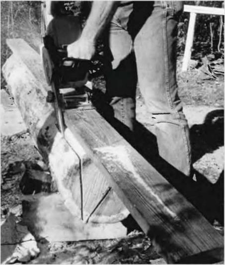
The Beam Machine is simply a 12-inch-long (30.5 centimeter) piece of channel iron welded to a pivoting mechanism which clamps onto the chainsaw’s bar with two strong setscrews. The channel iron fits neatly to the two-by-four that has been fastened along the log’s length. The mechanism allows the operator to import a vertical and straight cut as the unit is slid along the two – by-four guide track. All three of us tried the Beam Machine, and we found that we could rip the first slab off the edge of the log in about three minutes. We also tried Bruce’s saw, but it was not sharpened as well, and took considerably longer, pointing out the importance of a well-sharpened chain. We were all impressed with the smoothness of the cut using a regular chain.

After the first slab was cut away, we had a nice flat surface for remounting the two-by-four guide. Always, the Beam Machine must travel along the guide. We simply rotated the log by 90 degrees, so that we could work vertically once again on the adjacent (second) cut. We marked the small end of the log with a pencil, showing the square eight-by-eight cross-section of the beam that we wanted to make. Just before beginning a cut, we would barely tickle the end of the log with the saw to find out if we would, indeed, be cutting on the correct — outside — side of our line. On the second cut, I failed to keep the metal guide firmly on the two-by-four track and the saw came out of the other end of the log almost an inch out of plumb.

On this first test log, we also tried Bruce’s Granberg Mini-Mill, which operated on the same principle, but used a two-by-six guide instead of a two-by-four. Combined with a superior bearing for a pivot mechanism, we found the Granberg on its wider track was easier to keep on a straight vertical line. As we used the same saw, there was no difference in the time it took to make a cut.

In four cuts, we had a passable eight-by-eight post or beam, except that — thanks to my inexperience on the second cut — the last three feet of one end took a decided turn, so the cross section of that end is an inch out of square. Well, it would do as a post!

We made a nearly perfect eight-by-nine beam out of the next log, again using both machines. All dimensions were within a quarter-inch. Again, the $80 Granberg was easier to control than the $40 Beam Machine. In fairness, I think that with practice, an operator can do an adequate job with the less expensive tool, but if I were cutting a number of heavy timbers for a job, I’d say it’s probably worth the extra money for the Mini-Mill. Doug and Bruce concurred. All told, with experience, a sharp chain, and an adequately powerful saw, an eight – to ten- foot heavy timber should be possible to make every half hour with either of these simple chainsaw attachments.

image35

Fig. 3.3a: The Granberg Mini-Mill uses a wide two-by-six trackway for improved stability.


image36

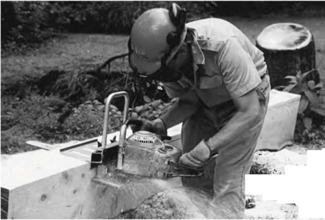
Fig. 3.3b: Doug Kerr cuts a slab off a fir log with the Beam Machine.

vertically-mounted chainsaw along the rail. About $80. Again, please see the Sidebar on pages 54-55.

• Alaskan Small Log Mill. This is the smallest of the Alaskan series of chainsaw mills, “perfect for the homeowner, woodworker or carpenter who owns a 3.8 cubic inch saw with a 20-inch bar,” according to the manufacturer. The Alaskan mills employ a different sort of guide from the Beam Machine or the Mini-Mill. The saw runs horizontally along the log, not vertically. The first cut is made using a plank guide, and additional cuts run along the first cut. About $120 in 2003.

• Basic Alaskan Mill. These mills range from the 24-inch Alaskan Mill, which will make a 20-inch (51 centimeter) cut ($150), all the way to the big 56-inch Alaskan Mill which will cut a 54-inch (137 centimeter) swath through the log ($220), although I can’t imagine why you would need any more than the 20-inch cut for making heavy timbers. None of the prices, of course, include the saw, special bar, or the special chainsaw milling chain, also called a “ripping chain.” It is not recommended to try to run any Alaskan Mill with a saw of less than 3.8 cubic inches of displacement, and larger is better.

• Complete Alaskan Mills. These are big, heavy-duty items and will allow you to cut wide thick slabs easily. You can hook up two chainsaw power heads to one bar and chain, which more than doubles the effective power. These mills run from $470 to $600, and the chainsaws, bars, and chains would add a great deal to these figures. [5]

narrow-kerf ripping chain supplied by Logosol, Richard was able to cut through white pine at a rate of about 3.2 feet per minute. Richard concludes, “For the hobby wood­cutter, the Timber Jig is a $155 investment that will probably pay for itself in short order. In touting the tool as an economy lumber maker, the manufacturer may be hiding the fact that its actually an excellent timber maker as well.

Подпись: Fig. 3.4: Richard Freudenberger tests the Logosol Timber Jig portable chainsaw mini-mill. Photo by Don Osby, reproduced by permission of BackHome Magazine, No. 66, p. 48.image37Even limited by its 8V^-inch (21.6 centimeter) depth, ripping out your own eight-by-twelve beams for a timber-frame project would save a bundle over buying them.” Richard’s complete article, with details of how to use the Timber Jig, is available in BackHome back issue No. 66. Write BackHome Back Issues, RO. Box 70, Hendersonville, NC 28793, call: (800) 992*2546 or log on to: www. BackHomeMagazine. com.

Both the Logosol and the various Alaskan Mills are a step up from the simple chainsaw guides like the Beam Machine and the Granberg Mini – Mill, and are recommended for larger projects. Yet another step up, and reflected in the cost, is the… [6]

An excellent source for purchasing many of these mills is Baileys, a woodsman’s supply house. Much of the information above comes from their 2003 Master Catalog. See Appendix C: Resources.

Making your own lumber with a chainsaw mill or bar guide is hard work, and great care must be taken both for safety and to maintain an acceptable standard of quality. Still, with a little practice, even the simplest guide attachments will yield good and useful heavy timbers.

Making timbers with a chainsaw presupposes that you are handy in the woods with the tool, as the first task will be felling the trees and maneuvering them to a clearing where you can work on the trunks. If you are not already an experienced woodsman, have someone who is teach you how to operate the saw safely and how to take down trees. Even better, take a chainsaw operation and safety course, as I should have done. I learned from experience and by necessity, but once, after about ten years of experience, I cut through a log and the tip of the saw kicked back on some hard object below. The bar, with the chain still moving, kicked back and bounced off my nose. It took a skilled plastic surgeon to make me into the good-looking guy I am today.

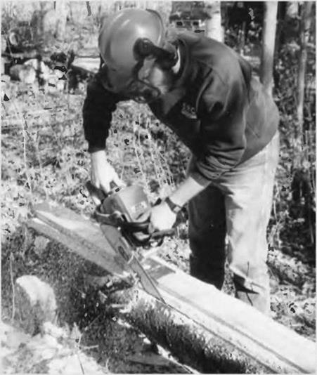
This book will not attempt to teach chainsaw skills. There are books and articles that do — you can search the internet — but a certified course is better. I will say that you should always wear safety chaps to protect your legs and body, and safety helmets for eye, ear and head protection. My son and I share a set of chaps, and, yes, they have been grazed on occasion. The reality is that chainsaws, handled incorrectly, can maim or kill, and so they must be treated with respect and vigilant concentration.

Having said all that, people comfortable with a chainsaw and not afraid of work can use these chainsaw mills to provide all the lumber they need, if they’ve got the trees. In a wooded building site, just clearing the house site itself, and a driveway to it, will often yield enough material to build a house. Just be careful out there!

HYDRAULIC DESIGN OF CULVERTS

Culverts convey surface flow from one side of the roadway to the other. Culvert design comprises three general considerations: culvert size, location, and shape. The size of the culvert is directly related to the results of the hydrologic investigation. The location of the culvert is derived from the site geometry and comprises the alignment, length, and

slope. The site hydraulics and available roadway fill height (height of fill from creek bed to profile grade) are the controlling criteria for determining the shape of the culvert. However, shapes, sizes, and material types used for culvert construction can be precluded from use based on manufacturing limitations. Since only the site hydrology and geomet­rics are known and all other parameters are variable, a trial and selection process must be used to determine the appropriate culvert size and type.

WELL-X-TROL QUICK SIZING FORM

(We suggest you make an office copy of this page when ready to calculate.)

For selecting WELL-X-TROLs for a different running time than ESP I or ESP II, and/or at pres­sure ranges the same or different than 20/40,30/50, 40/60:

THINGS YOU MUST KNOW

1, System flow rate (pump capacity or discharge) GPM


. Min.

. Psig. Psig

. ESPVol.


2. Desired running time, in minutes and fractions of minutes (1.5 min. = 1 min. 30 sec )

3. Pump cut-in. in gauge pressure

4. Rump cut-out, in gauge pressure

CALCULATING TANK SIZE

5. Multiply Line 1 by Line2 and enter ESP Volume

  WELL-X-TROL QUICK SIZING FORM

, P. F.


, Gals.


Refer to Table 2 and select WELL-X-TROL model that is greater than Line 7 tor “Total Volume” and Line 5 is less than “Maximum ESP Volume"

  WELL-X-TROL QUICK SIZING FORM

THINGS YOU MUST KNOW

1. System flow rate (pump delivery)


12.5 GPM


1.5 Min. 25 Psig 45 Psig


2. Desired running time, in minutes and

fractions of minutes(1.5 min. = tmin.30sec.)


3. Pump cut-in. in gauge pressure

  WELL-X-TROL QUICK SIZING FORM

18.8 ESPVol. 34 P. F.


7. Divide Ltne 5 by Line 6 and enter minimum total WELL-X-TROL volume


55.2 Gals

  WELL-X-TROL QUICK SIZING FORM

WX-251


FIGURE 8.35 ■ Pressure tank sizing form. (Courtesy of McGraw-Hill)


WELL-X-TROL QUICK SIZING FORM

WELL-X-TROL QUICK SIZING FORM

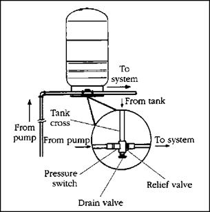
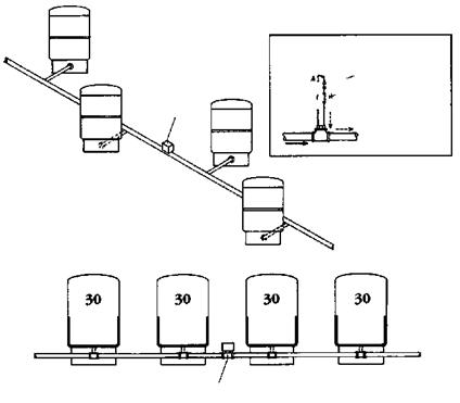
FIGURE 8.36 ■ Tank tee being used with a stand – type pressure tank. (Courtesy of McGraw-Hill)


To

WELL-X-TROL

Union

If /’^–Shut-off Г ’’ valve


WELL-X-TROL QUICK SIZING FORM

To system


WELL-X-TROL QUICK SIZING FORM

psig


psig


psig


psig


Pressure switch


WELL-X-TROL QUICK SIZING FORM

WELL-X-TROL QUICK SIZING FORM

FIGURE 8.37 ■ Diagram of multiple pressure tanks being installed together. (Courtesy of McGraw-Hill)

The appearance of the water mill

The water mill, the first energy source to replace muscle power, appears in the Hellenistic cultural sphere at the end of the 2nd or beginning of the 1st century BC. The region of origin of this important invention, somewhere in Asia, is not well known. The first traces are claimed to be from the kingdom of Pontus, at Cabeira, by Strabo (who is a native of that region), in the proximity of the new palace of Mithridatus VII Eupator, king of Pontus from 111 to 63 BC. He fought against the Roman expansion in the region, but was finally defeated by Pompey in 63 BC.

“… at their junction (i. e. of the two rivers Lycos and Iris) is situated a city which the first man who subjugated it called Eupatoria after his own name, but Pompey found it only half-fin­ished and added to it territory and settlers, and called it Magnopolis. Now this city is situat­ed in the middle of the plain, but Cabeira is situated close to the very foothills of the Paryadres mountains about one hundred and fifty stadia farther south than Magnopolis, the same dis­tance that Amaseia^1 is farther west than Magnopolis. It was at Cabeira that the palace of

Mithridates was built, and also the water-mill; and here were the zoological gardens, and, near

32

by, the hunting grounds, and the mines.”

Another piece of written evidence, essentially from the same time as the text of Strabo, is attributed to Antipatros of Thessaly. It speaks poetically of the new pleasures to be enjoyed by the miller, liberated by hydraulics from the need to turn the mill with his own muscles. It also suggests that this is a recent invention:

“Women who toil at the querns, cease now your grinding;

Sleep late though the crowing of cocks announces the dawn.

Your task is now for the nymphs, by command of Demeter,

And leaping down on the top of the wheel, they turn it,

Axle and whirling spokes together revolving and causing The heavy and hollow Nisyrian stones to grind above.

So shall we taste the joys of the golden age

33

And feast on Demeter’s gift without ransom of labour.”-”

Some see in this sentence the proof that the mill to which the text refers (the one at Mithridatus? Another mill?) has a vertical axis and horizontal wheel (the Nymphs turn the axle in bounding to the top of the wheel). But this would appear to be thin proof at best. It is only under the Roman Empire, and in particular during the 1st and 2nd cen – [192] [193] [194] [195] turies AD, that the use of the water mill spreads into the Roman provinces of Asia and the West. We will return to this in more detail in Chapter 6. Note that in China we find hydraulic energy applied to complex industrial uses as early as the 1st century AD, (Chapter 8).

Organizing Principles

The success of a work of art hinges, more than anything else, on the strength of its composition. Here the term "composition” is used to mean "a whole comprised of parts.” A strong composition is one in which all its parts work to strengthen the whole. This is as true of a piece of music as it is of a painting or the design of a small house.

The last chapter described subtractive design as the means to distilling a house to its essential components. This chapter will focus primarily on how the remaining parts are to be organized into a comprehensive whole. Seven principles: simplicity, honesty, proportion, scale, alignment, hierarchy and procession will be presented as essential considerations to meeting this end.

Soil Gas Management

A variety of natural and human-caused soil gases can infiltrate structures and lead to in­door air quality problems. Soil gases can be sucked into basements, crawl spaces, and floor slabs if negative pressurization exists within or under a structure. You can prevent this prob­lem by creating a physical barrier between the soil and the home and by controlling the air pressure conditions under and within the home.

Harmful human-source soil gases include

trie company sent a team of specialists to his house to investigate. The readings on the Geiger counter showed levels 700 times higher than the maximum considered safe for human exposure. Researchers concluded that the culprit was radon, a naturally occurring radioactive gas derived from underground uranium.

Discussion

At that time, very little was known about radon and its health effects. The Watras house was used as a laboratory for radon researchers who wanted to learn how radon gets into a house and how to get it out. Low-grade uranium ore was discovered beneath the basement of the structure, in direct contact with the house. The foundation of the house was removed, along with the soil under­neath, to a depth of four feet. Ventilation fans were installed to pull radon-laden air out from under the house. Watras and his family were eventually able to move back into their home.

pesticides, herbicides, and gases from nearby landfills or industrial sites. In new construc­tion, most of these problems can be avoided through careful site selection and through home and yard maintenance that is free of toxic chemicals.

Water vapor and radon gas are two natu­rally occurring soil gases that may infiltrate a structure and result in health problems. The intrusion of water vapor into the home may cause structural damage and mold prob­lems. These gases are both easily dissipated or blocked from entry by installing appropriate controls during the construction process.

Radon Gas Infiltration

Radon is a clear, odorless gaseous byproduct of the natural breakdown of uranium in soil, rock, and water. While radon gas dissipates in open spaces, it tends to cling to particu­late matter and accumulates when enclosed. When inhaled, radioactive particles become lodged in the mucous membranes of the re­spiratory system. The Surgeon General has stated that radon exposure is second only to tobacco smoke as a cause of lung cancer.

It has been estimated that as many as one in 15 homes in the United States contains ele­vated radon levels. The EPA recommends mit­igation at levels higher than 4.0 picocuries per liter of air. Even at 4.0 picocuries per liter, there is an increased risk of lung cancer. Therefore, reducing radon to between 1.0 and 1.5 pico­curies per liter is a prudent target, ensuring a margin of safety.

Radon mitigation is most effective and least costly when incorporated into the con­struction of the home. If you are building a new home and there is reason to suspect a ra­don problem, a soil test is advisable. Although the test will not tell you definitively what the radon levels will ultimately be in the finished home, it will help you decide whether to in­clude mitigation measures in your construc­tion plans. For more information about this test, refer to Division 13.

Habitat Houses—Built to Take a Licking

Habitat Houses—Built to Take a Licking

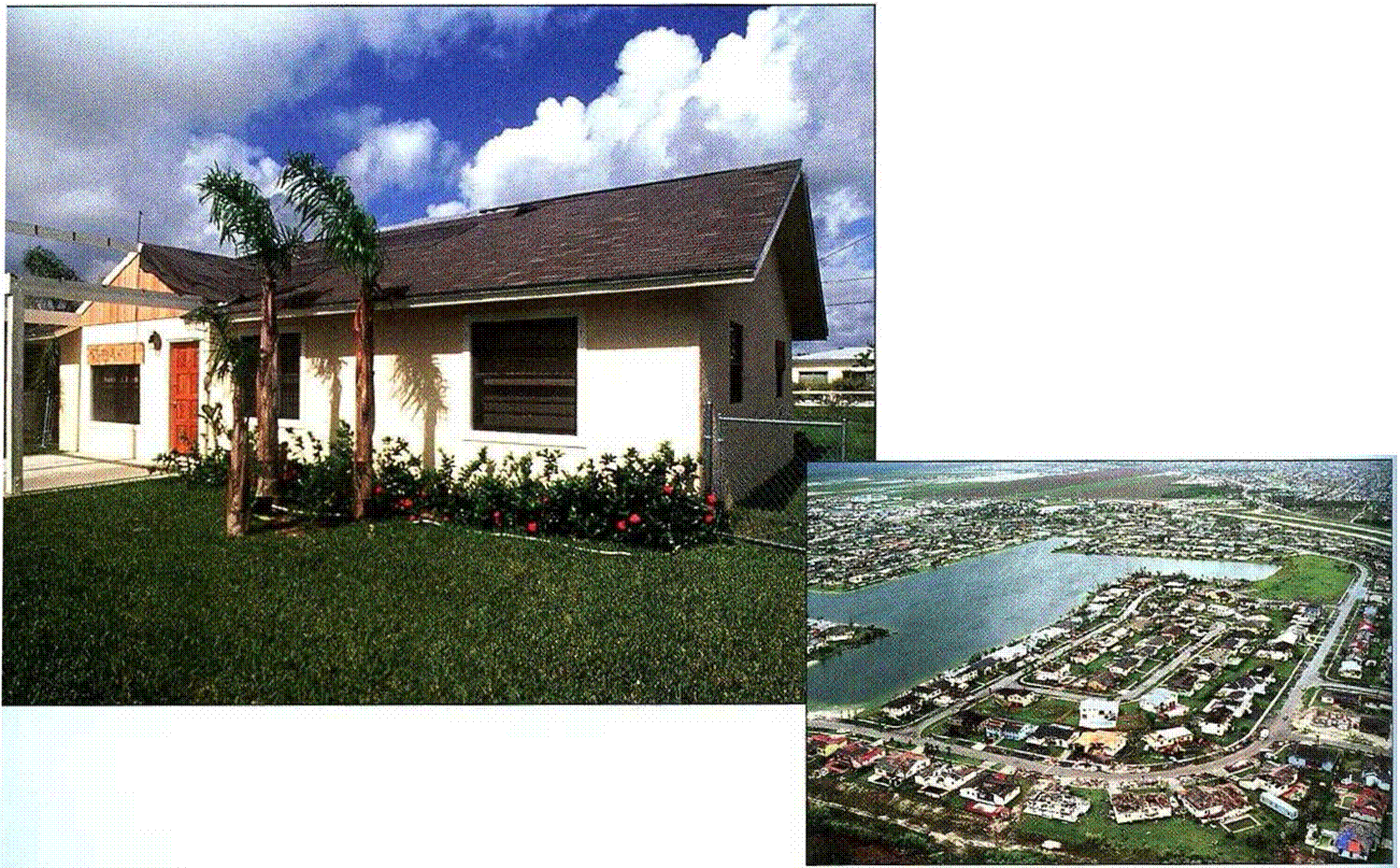
THE MOST DEVASTATING natural dis­aster in the history of the United

/

States began to take shape off the west coast of Africa on August 14, 1992. Gathering strength as it made its way across the Atlantic Ocean, the storm that came to be known as Hurricane Andrew finally made land – fall at Homestead, Florida, just alter 5 a. m. on August 24th. With sus­tained winds of 145 mph and gusts exceeding 175 mph, Andrew was no
run-of-the-mill hurricane. Although the death toll was relatively low for a storm of this intensity (40 people died as both a direct and an indirect result of Andrew), the economic damage exceeded $25 billion.

As it turns out, Habitat had built or rehabbed 27 houses in Homestead and in the nearby communities of Liberty City and West Perrine. A few

^ 4

days after the storm, Kevin McPeak, Habitats regional administrative
coordinator, drove out to survey the damage.

Hoping for the best but bracing himself for the worst, Kevin was astonished and elated as he discov­ered, house by house, that everyone of the Habitat homes had survived Andrews onslaught. Carpets were ruined and windows were broken; a few houses had even shifted a bit on their foundations. But compared to most of the houses around them, the 1 Iabitat houses stood tall. Clearly, Habitat knows how to build houses.

A BALANCING ACT. The ability to walk on the wall plates is helpful when installing roof trusses, but you can also do the work from a ladder or from staging set up inside the house.


Habitat Houses—Built to Take a Licking

ladder or a scaffold instead. To make it casv to move trusses into position, I like to build a catwalk, or walkway, over open sections, such as the living room. (For directions on howto erect a catwalk, see the illustration at right.)

Egypt under the Lagide rulers: development of irrigated agriculture

A constant preoccupation of the Lagide kings, pressured by their politics of prestige and expansion, was to increase agricultural productivity. Each region (or nome) is under the responsibility of an economist (the Greek name is Oikonomos), charged, among many other tasks, to “control the delivery canals across the fields, from which the peasants draw water conveyed to their cultivated fields; to verify that the feeder canals have the prescribed depth, and that their interior space is sufficient.”[183] Every retention basin has its irrigation controller (catasporeos) responsible for water distribution.

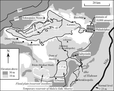
Under Ptolemy II, the region of Fayoum, already made productive during the era of the pharaohs, is brought under a new development policy. In Chapter 3, we have dis­cussed the legendary Lake Moeris, and the works realized since the time of the pharaohs (Figures 3.6 and 5.11). The capital of the region, the ancient Shedet of the Egyptians that the Greeks called Crocodilopolis,[184] is renamed Arisone, again in honor of the queen. The ancient hydraulic systems are renovated, new projects undertaken, and the lake level lowered. A chief engineer named Cleon is charged with management of the new developments of Fayoum.

Egypt under the Lagide rulers: development of irrigated agriculture

Figure 5.11. Fayoum in the Hellenistic era. We have shown the hydraulic works identified by Garbrecht and Jaritz (1992), and shown the level of Qaroun Lake at the elevation -10 m.23 The level reached by the Nile in flood is about 30 m.

Thus, when the minister of the Treasury, Apollonius,[185] [186] receives from the king Ptolemy II Philadelph a concession for the development of a vast domain of 2,700 hectares in Fayoum, he relies on the services of Cleon to establish the economic plan­ning and the layout of the hydraulic infrastructure (Figure 5.12). The correspondence of a certain Zenon of Caunos, who is successively secretary for Apollonius then manager of this domain, gives us a vivid illustration of certain aspects of water resource manage­ment in the region. In 258 BC Apollonius has the upper zone of the basin, to the north­east, developed as the “domain of ten thousand aroures”. A new city called Philadelphia is founded nearby. Certain conflicts of interest were inevitable between Cleon the engi­neer and Zenon the exploiter, as evidenced in the correspondence of Zenon:

“Zenon to Cleon, greetings! The water in the canal has not risen more than a cubit, so the

land cannot be watered from it. Therefore you would be well advised to open the gates to water the land. Stay well! (October 258 BC)

“Panakestor to Cleon, greetings! We sent you a letter on the 19th, asking you to provide us with a team to do maintenance on the bends of the small canal. Well, it seems that you have left us aside in going toward the Small Lake. Instead of avoiding us as you have done, your duty was to meet with us briefly, and having seen for yourself that the land is not being watered, to ask yourself why. Your job is not only to direct the infrastructure works in the region of the Small Lake, but also here. So, at least come meet us tomorrow at the lock and sketch out for us the path canal bends should take, for we do not have this experience. We will provide you with the labor and other facilities, whatever you command. But if you do not come, we will be obliged to write to Apollonios that his land is the only land not to be irri­gated in the region of the Lake. So, we are more than ready to make all needed facilities avail­able for you. Stay well. (October 257 BC).[187]

Is it possible that the “Small Lake” in this letter is the reservoir of Mala’a (the lake Moeris of Strabo) to the southeast of Fayoum? This seems to be the chief engineer’s main preoccupation, to the point that he neglects the domain of the minister. It is indeed thought that the works controlling this lake, the dam of Mala’a in particular, were con­structed at about this time.[188] The “domain of 10,000 aroures”, to the northeast, is irri­gated by a derivation from the Joseph canal (or Bahr Youssouf), the derivation works quite probably located near the Labyrinth. This domain includes parcels that are locat­ed on higher ground compared to the other cultivated land of the region. The lower lands must be irrigated first, which causes friction with the villagers outside the domain who think that their water has been confiscated:

“Psenemous to Zenon, greetings! The outlying peasants have taken out their (mules and shovels) and opened the irrigation ditches at the ends of the ten thousand aroures. People from Philadelphia attacked them, (chasing away) the mules and breaking (the shovels). I sent Pelois, son of Pachos, to (tell you of this). But I presume that you already know of these ugly incidents. In order that this business be cleared up as soon as possible, you would do well to order that (their land) be supplied with water. [.. .][189]

Thanks to irrigation, numerous new fruits are adapted and cultivated in Fayoum: olives, pears, apricots, figs, etc. In addition, during this period an attempt is made to develop grains yielding two annual harvests: the first planted at the falling flood, in October, and the second irrigated artificially. This is the sense of a written instruction send to Zenon:

“Apollonius to Zenon, greetings! The King has ordered us to cultivate the land a second time. Therefore, as soon as you have harvested the early grain, quickly water the land by hand. In case this is not possible, install as many irrigation machines as you can, but do not leave water on the land more than five days. Then dry the land and as quickly as possible plant the three-month wheat. Write to me personally when you are ready to harvest the
grain. Go well” (December 256 BC).[190]

The “irrigation machines” of this letter are perhaps balance beams (shadufs), or per­haps the very first models of manual waterwheels that appear in the 3rd century BC.

Two centuries after these accounts, at the beginning of the Roman domination around 25 BC, Strabo sojourns in Egypt and travels up the Nile to Aswan, in the com­pany of the prefect, newly named by Augustus. Twice in his accounts he speaks of irri­gation by “machines” (always powered by men or animals) and, in particular, the use of

Подпись: West “Sketch by Stothoetis [...] for Appollonius in the year 27, the [...] of the month of Phaophi (..., i.e. December 259 BC) under the responsibility of Zenon (?) and the control of Diodore. “The perimeter of the ten thousand aroures is 400 schoenes (this clearly refers to hundredths of schoenes) along four dikes. In the interior, from south to north, there would be three dikes, separated one from another by 25 schoenes, and in addition, from east to west, nine transversal levees, separated by 10 schoenes. There would be, therefore, within , 1km , East the ten thousand aroures, forty basins of 250 aroures each (69 ha), measuring 25 by 10, as shown on the plan, which represents sixteen dikes each of length 100 schoenes, i.e. 1600 schoenes in all, for which it would be necessary to excavate the fill dirt. “The width of a ditch is 4 cubits, the depth 2; we estimate that one will be able to extract enough dirt to raise the dikes to the desired height, which will be done. [...] As for the four supply canals that must be added to the four existing ones, they will each be 100 schoenes long. [...] If this work is completed during the winter, we estimate that it will be costly. [...]”

Figure 5.12 Plans for development of the “domain of 10,000 aurores” and reproduction of a descriptive sketch (Orrieux, 1983; Burkhalter, 1992)

Archimedes Screws and wheels; first in the region of Memphis, then in the region of Aswan.

“There is a ridge extending from the encampment (the cantonment of a Roman legion) even as far as the Nile, on which the water is conducted up from the river by wheels and screws; and one hundred and fifty prisoners are employed in the work; and from here one can clear­ly see the pyramids.. ,.[191]

“The Nile has very many islands scattered along its course, of which some are wholly cov-

ered at its risings and others only partly; but the exceedingly high parts of the latter are irri – 30

gated by means of screws.”