DRILLING HOLES

With the boxes in place, drill holes to run cable from the service panel to the outlet boxes. As noted earlier, a h-in. right-angle drill with a 7/-in. Nail Eater wood-boring bit is the tool of choice.

For individual circuits, in which a cable serves only one appliance, reduce the amount of hole drilling by drilling up through the top plate(s) above the appliance and running cable through the attic till you’re above the service panel. Then drill holes down through the wall plates so you can drop the cable to the panel.

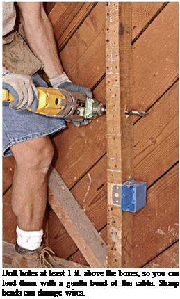
For circuits with many wall outlets, drill through studs 12 in. above the outlet boxes, so the cable can bend gradually toward the boxes. (Avoid sharp bends, which can damage wire insu­lation.) All holes should be centered in the studs, so that the cable is at least 1’/ in. away from the stud edges; that way drywall screws can’t punc-
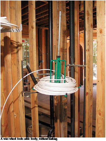
Подпись: A wire wheel feeds cable freely, without kinking. Подпись: Staple cable within 8 in. of singlegang plastic boxes and within 12 in. for all others. Cables should lie flat beneath the staple; never staple cable on-edge.Подпись: PROTIP The NEC requires at least 6 in. of "free" wire in a box, and at least 3 in. of it can extend beyond the front of the box. But seasoned electricians usually leave more wire sticking out. For inspectors, short stubby wires are the mark of an amateur. 1111 image490

ture it. If a cable is closer than 114 in., nail steel nail-protection plates to the studs. Be careful to drill holes at the same height. It’s much easier to pull cable through lined-up holes. A right-angle drill will also ensure that the holes are perpendi­cular to studs.

Sometimes it’s easier to run cable around an obstruction. For example, it’s possible to run cable through the corner studs if the holes are at the same height and there’s no 2 X blocking at the point where you drill. But if you’re running 12/2 cable or heavier, the cable will be too stiff to pull through the holes at right angles. In this case, drill through the wall plates and go over or under the corner. Likewise, drilling through dou­bled studs on either side of a door or window opening is a lot of work. So go around.

Finally, drill holes for cable "home runs”— lengths of cable that run from the panel board to the outlet box on each circuit that is closest to the panel.

PULLING CABLE

Pulling Romex cable is easier if you reel it off a wire wheel, a rotating cable dispenser that nails to framing and holds 250-ft. coils. Start by plac­ing the wire wheel near each home-run box and pulling off enough cable to extend roughly 1 ft. beyond each box and 4 ft. beyond the knockout where each cable enters the panel. When in doubt, run cable long. For example, wires inside a service panel may need to run 3 ft. to 4 ft. to reach a neutral or ground bus on the opposite side of the panel.

To run cable for individual circuits, again place the wire wheel near each home-run box, but this time pull cable "downstream”—away from the service panel. Many electricians pull cable through holes to the far end of the circuit and then walk back, pulling out additional cable loops that reach at least 8 in. beyond each box. After running cable to all outlet boxes, cut each loop and feed the cable ends into the box open­ings or knockouts, so the cables stick out about 8 in. Although most duplex receptacle boxes will contain two cables, double – or triple-gang boxes may have four or more.

Staple cable within 12 in. of most boxes, and every 4h ft. thereafter. However, if you’re using single-gang plastic boxes without internal cable clamps, staple cable within 8 in. of the boxes. Don’t overdrive the staples; cable should be just snug. When cable runs parallel to joists, staple it to the sides of the joists. When cable runs per­pendicular to joists, drill holes through the joists or staple the cable to the underside of each joist. Alternatively, you can nail a 1 X 4 board to the underside of the joists and then staple cable to it.
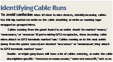
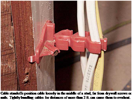
Подпись: Identifying Cable Runs To avoid confusion when it's time to wire devices, identify incoming cables. Use felt-tip markers to write on the cable sheathing or write on masking tape wrapped on grouped wires. Cables running from the panel board to an outlet should be marked "SOURCE," "FROM SOURCE," or "UPSTREAM." If you're wiring GFCI receptacles, these incoming cable wires attach to GFCI terminals marked "LINE." Cables running on to the next outlet (away from the power source) are denoted "NEXT OUTLET" or "DOWNSTREAM"; they attach to GFCI terminals marked "LOAD." Double- or triple-gang boxes will have a lot of cables entering, so make the cable descriptions specific: "SWITCH LEG TO CEILING FIXTURE," "THREE-WAY SWITCH #2," and so on. Подпись: Cable standoffs position cable loosely in the middle of a stud, far from drywall screws or nails. Tightly bundling cables for distances of more than 2 ft. can cause them to overheat. Подпись: TIP CABLE CONNECTORS (CLAMPS)Подпись:

Подпись: Use a screwdriver or lineman's pliers to remove the metal box knockouts. Cables entering through such openings must be protected by cable connectors.
image492

All outlet boxes must have clamps that grip cables, except single-gang plastic boxes whose cables must be stapled within 8 in. of the box. (Several Romex connectors are shown in the photo on p. 243.) Clamps secure cable so its con­nections can’t be yanked—thus preventing strain on connections inside the box. Plastic boxes have tension clamps that allow cable to be pulled in, but not out. When you’re fishing wire and installing cut-in boxes, cable clamps are crucially important because it’s impossible to staple cable hidden by walls.

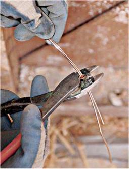
Cable clamps in metal boxes also keep wires from being nicked by burrs created when metal box knockouts are removed. (Use a screwdriver to start knockouts and lineman’s pliers to twist

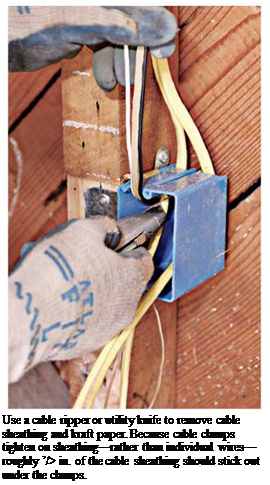
them free.) To further protect wire insulation, leave a small amount of cable sheathing—roughly h in.—sticking out from under clamps. That is, clamps should tighten down on a remnant of sheathing, not on individual, unsheathed wires. Finally, don’t overtighten clamps, which could damage the wire insulation. And if you remove a knockout mistakenly, use a knockout plug to cover the hole; a knockout plug is a thin cap with barbed sides or spring clips that expand after they clear the edge of the knockout hole. Use one cable per clamp unless the manufacturer allows more.

STRIPPING SHEATHING

Many electricians use a utility knife to slit and remove plastic sheathing, lightly running the blade tip down the middle of the cable, over the bare ground wire inside. To remove sheathing with less risk of nicking wire insulation, use a cable ripper to slit the sheathing or a cable strip­per to remove a sleeve of sheathing. Use a utility knife or side-cut pliers to cut free any slit sheath­ing or kraft paper still in the box. Tighten the cable clamps; then group like conductors—hot wires to one side, neutrals to the other, grounds in the middle—and cut all wires to the same length, roughly 8 in.
Подпись:

Подпись: Crimping ground wires is quicker than splicing them with wire nuts. After crimping the sleeve, leave one ground wire long. Then attach it to the green ground screw of a receptacle.
image494

Splicing ground wires. To ensure a continuous ground throughout the system, splice together copper ground wires, using wire nuts or crimps. Ground wires are usually bare copper; if they’re green insulated wires, first strip approximately % in. of insulation off their ends.

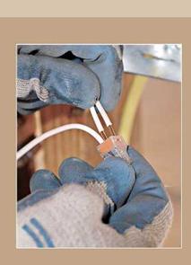
To use wire nuts, first cut the ground wires to the same length, and butt their ends together, along with a 6-in. pigtail that you’ll later connect to the green ground screw of a receptacle. (The grounding pigtail can be bare copper or insulated wire whose ends have been stripped.) Use line­man’s pliers to twist the stripped wire ends clock­wise. Trim the ends of the grouped ground wires even; then twist on a wire nut, turning it in a clockwise direction. The threads inside the wire nuts cut into and bind the bare wires. Give a gen­tle tug to be sure the splice is complete.

To crimp ground wires, gather the wires but don’t twist them. Feed them through a copper sleeve, use a crimping tool to crimp the sleeve tight before snipping all the wires—except one— even with the sleeve. This one long ground wire emerging from the crimped group will connect to the green ground screw of a receptacle. You can use wire nuts to splice (join) ground wires; but crimping them is faster.

If the box is metal, it too must be grounded. Many electricians simply loop the bare-wire grounding pigtail and screw the loop to a green screw in the metal box. The bare-wire pigtail then continues on, to connect to the grounding screw on the receptacle. Or you can add a second pigtail to the ground-wire splice, so that the first screws to the metal box and the second to the receptacle, but that eats up space in the box and slows down the work.

At this point, most local codes require a rough-in inspection. In addition to outlet boxes, inspectors will examine any connections in junc­tion boxes, typically 4-sq.-in. boxes. All electrical connections must be housed in covered boxes, but you must leave junction box covers off till the rough-in inspection is done.

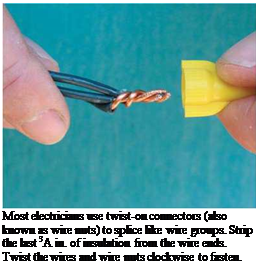
Splicing neutral and hot wires in outlet boxes is essen­tially the same as splicing ground wires. Once again, a pig­tail runs from both the hot and the neutral wire groups and attaches to the appropriate screw terminal on the recepta­cle. Because neutral and hot wires are always insulated, use wire strippers to strip the insula­tion off the wire ends.

Подпись: Most electricians use twist-on connectors (also known as wire nuts) to splice like wire groups. Strip the last 3A in. of insulation from the wire ends. Twist the wires and wire nuts clockwise to fasten. Feed the wire into an appro­priately sized hole in the tool’s jaws, squeeze the handles, and rock the tool so it cuts the insu­lation but doesn’t score the con­ductor. If you are using wire

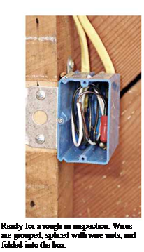
Подпись: Ready for a rough-in inspection: Wires are grouped, spliced with wire nuts, and folded into the box. image497nuts to splice wire groups, strip roughly M in. of insulation from the wire ends; then twist each wire group together, using lineman’s pliers. If you are attaching a pigtail to the receptacle or fixture screws, strip h in. of insulation. Back-wired switches and receptacles have stripping gauges on the back that show how much to strip.

At switches, do not splice hot wires; splice only neutral and ground wire groups. Switches turn fixtures off and on by interrupting the cur­rent flowing through hot wires. Therefore, you must attach hot wires to switch terminals, not to each other.

Cutting cripples and trimmers

Keep your mind focused when measur­ing and cutting cripples and trimmers.

A mistake here can cause you big headaches and lots of extra work later on. I recall cutting all the top window cripples 1 in. too long for the first floor of an apartment house we were build­ing. I didn’t catch the mistake until after the walls were framed and raised. Every window and door header had to be removed and the cripples shortened. Not a good way to start your week.

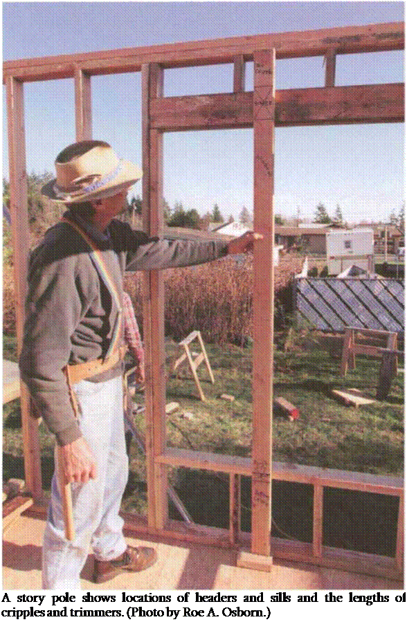
To make the job of cutting cripples and trimmers easier, I usually make a story pole. As the name suggests, this is a pole—actually a 2×4—that tells a story, and it’s used to mark multiple measure­ments or to transfer measurements from one place to another. A story pole can be used to show the locations of headers and sills or the lengths of cripples and trimmers (see the photo at right) or to locate the height of rows of siding (see Chapter 8).

Подпись: A story pole shows locations of headers and sills and the lengths of cripples and trimmers. (Photo by Roe A. Osborn.) To make a story pole for а 9б3Л-іп. wall, take a 921/4-in.-long 2×4 and tack a short piece of 2×4 to one end to act as the bottom plate. Since the height of both the door and window headers from the floor is generally б ft. 10 in., measure up this distance from the bottom of the bottom plate and mark the location of the bottom of the headers. Then measure up from this mark another ЗУ2 in. for a 4×4 header and 5У2 in. for a 4×6 header. Measure up 1У2 in. for a single flat header, or 3 in. for a double flat header.
Cutting cripples and trimmers

Left over on the pole are the lengths of the top cripples: 6У4 in. for the 4×6 header, 8У1 in. for the 4×4 header,

ЮУ4 in. for the 2x flat header, and 83/4 in. for a double flat header. Cut enough top cripples to nail one on each end of every header and one every 1 б in. on center (o. c.) between.

To determine the length of the door trimmers, measure down from the bot­tom of the header to the top of the bottom plate. This distance is б ft.

8У2 in. To make the trimmers fit snug, add about У16 in. to this length, which you usually can do by leaving the line when you cut.

Window trimmers for aluminum – or vinyl-clad frames are the rough-opening size of the window. If you have a window that is 5/0 high, the trimmer will be 60 in. For wood-frame windows, add 3 in. to make room for the wood sill.

To find the lengths of the cripples under a 5/0 window, measure down 60 in. and make a mark. Measure down another 11/2 in. for a single 2x rough sill. The amount left over on the stud—19 in.—is the length of the bottom cripples.

MARKING THE PLATES

Once all the parts have been cut, you have to figure out where to nail them. When I first began as a carpenter, I used to plate, lay out, and build one wall at a time. Now I start by laying out (detailing) where every piece nails into every wall plate. I indicate on the plates the loca­tions of corners, doors, windows, and
every stud. It’s best to keep these detail marks on wall plates simple. Extra marks tend to be confusing.

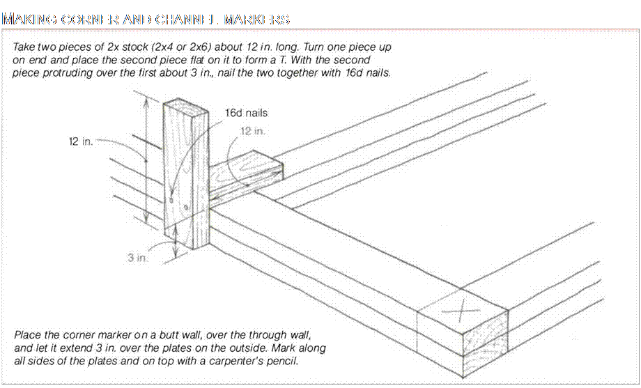
Start by marking the corners and chan­nels (the T-intersection where one wall meets another). Corners and chan­nels require extra studs so that walls can be properly nailed together once they are raised. These extra studs also provide backing so that the drywall can be nailed on the inside and siding on the outside. Mark the locations of these corners accurately on the plate so that raised walls will be nailed in the right place.

Подпись: MAKING CORNER AND CHANNEL MARKERS
A bit of sloppiness is allowed in frame carpentry. Wall plates, for example, can be Vs in. short or long without causing major problems. But inaccuracies tend to accumulate. A small mistake made several times can add up to a headache.

Подпись:So a skilled craftsperson is one who learns to work quickly and, most impor­tant, with precision.

One quick and accurate way to mark corners is with a corner marker (see the drawing on the facing page). Use the corner marker as shown in the drawing to scribe layout lines for corners and channels, which will show exactly where to nail in the extra studs needed at these points. It also marks where to cut the second plate (double top plate) that is nailed to the first top plate as the walls are being framed.

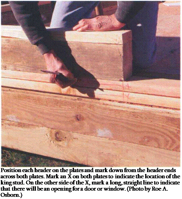
Now, following the plan, find the loca­tion of each window and door. Position each header on the plates and mark down from the header ends with a piece of blue or black keel across both plates. Next to this line, mark an X on both plates on the side away from the header to indicate the location of the king stud that nails alongside the header. On the other side of the line awayfrom the X, make a longer, straight line along both plates. This line indicates that there will be an opening for a door or window at this location (see the photo at right).

Wall studs are usually 1 б in. o. c. or 24 in. o. c., but you never know what to expect on a remodel job. I worked on an old house once in which the studs were about 5 in. o. c. Both the outside and inside were sheathed with 1x pine.

Good construction, but it would be rather expensive these days. At least it was no problem to hang a picture on the wall. [8]
from Pairis Enterprises (see Sources on p. 198). Laying out with this stick is cer­tainly faster than using the 6-ft. folding rule I started with as a beginner. Most metal tape measures are clearly marked on 16-in. and 24-in. centers and can also be used for layout.

Every carpenter needs to become famil­iar with specialty tools like the layout stick. I seldom use a tape measure to lay out studs or plates simply because it’s faster and just as accurate to use a lay­out stick.

Exterior walls often are sheathed with plywood or oriented strand board (OSB), materials that come in 4-ft. by 8-ft. sheets. So wall studs need to be spaced

Подпись: Use a layout stick to mark stud locations on wall plates. (Photo by Roe A.Osborn.)
to fit the 4-ft. module of the sheathing. Otherwise, every piece of sheathing has to be cut to fit, a wasteful, time – consuming process. Start the stud layout at one end of the first exterior wall, being sure to detail stud layout on the same side of the plate as the door and window layout. If you are using a layout stick, set it with the legs down over both plates and scribe along both sides of the second, third, and fourth legs at the 16-in., 32-in., and 48-in. marks (as shown in the photo above). Then move the stick and scribe another set of studs until you come to the end of each wall.

If you’re using a tape measure, hook it over the end of the plate and pull it as far as it will extend, marking on every 16-in. or 24-in. layout mark. When you come to a window or door, transfer layout marks onto headers and rough sills to indicate where the cripples will be nailed.

Self-Cleaning Windows Reduce Maintenance Demands

For those of you who say, "I don’t do windows," technology has finally caught up with your sentiment. Several big glass companies market coated glass that resists the buildup of dirt. Product names include Neat® Glass by Cardinal, Activ™ by Pilking – ton®, and PPG’s SunClean®.

By making the glass smoother and hy­drophilic, rainwater collects in sheets on the surface and slides off the glass quickly, clean­ing the window. Some windows include a titanium-dioxide layer that reacts with UV – light to help organic materials decompose, so dirt washes away more easily.

Window Styles

DOUBLE-HUNG

Traditional window composed of two sashes that slide verti­cally. A single-hung window looks identical, but the top sash is fixed.

Pros: Available with a wide va­riety of grille patterns to match different architectural styles.

Sashes usually tilt in for easy cleaning of the exterior.

Cons: Sashes rely on draftier sliding-style weatherstripping. The bottom edge of the upper sash is exposed to outdoor tempera­tures on two faces, increasing surface area for thermal bridging. Two sashes increase spacer area, increasing U-factor. Less than half the window area can be open for ventilation.

Self-Cleaning Windows Reduce Maintenance Demands

AWNiNG

Top-hinged window that usually opens outward with a crank.

Pros: Good-sealing compression-style weatherstripping. Single glass unit and re­cessed sash improve U-factor. Provides ven­tilation while it’s raining. Often used above and/or below large fixed windows for venti­lation and additional daylight.

Cons: Screen on inside of window. Open window can present a hazard if installed along a walkway, deck, patio, or porch.

TiLT-AND-TURN

Dual-action window that can swing in like a door or tilt from the bottom like a hopper window for ventilation.

Pros: Ventilation options. Secure multipoint locking. Compression weatherstripping. Large egress area and easy cleaning.

Cons: Shades and drapes can interfere with operation.

CASEMENT

Side-hinged window that usually opens outward with a crank. In-swing versions are available.

Pros: Compression-style weatherstripping. Single large glass unit and recessed sash im­
prove U-factor. Largest ventilation area of any window style. Opening can be oriented to "scoop" prevailing breeze.

Cons: Screen on inside of window. Hinge design might not allow outside of window to be cleaned from inside. Open window can present a hazard if installed along a walk­way, deck, patio, or porch.

HORiZONTAL SLiDER

The two sashes slide past one another on tracks like a sliding patio door.

Pros: Can be easier to open than other slid­ing styles, especially when placed over a counter.

Cons: Sliding weatherstripping and greater sash area lower U-factor and airtightness ratings.

FiXED

An inoperative window available in shapes that match operable windows, or as accent windows such as half-rounds to create Pal- ladian windows and octagons.

Pros: Improved airtightness. Can be made in nonstandard, custom shapes.

Cons: Doesn’t satisfy egress requirements.

Подпись:Self-Cleaning Windows Reduce Maintenance DemandsHOPPER

Tilt-in bottom-hinged window.

Pros: Compression-style weatherstripping. Single glass unit and recessed sash improve U-factor.

Cons: Hazardous if installed at head height or lower.

Choosing

Replacement

Windows

You have three choices for replacing exist­ing windows: a sash-only replacement; an insert-style frame and sash replacement win­dow; or a new-construction window.

If the existing frames have water damage, the only choice is a new-construction win­dow (see the photos on p. 92).

If you’re looking to improve comfort or energy performance, replacing the sashes or using a frame insert can help. They’re a good choice on older homes where you want to preserve period trim, but from an energy and comfort standpoint, they’re not the best option.

Replacement windows that leave the existing frame in place don’t stop air leak­age. If you’ve ever pulled out an old win­dow, then you’ve seen fiberglass insulation stuffed between the window and the rough opening. Typically, the insulation is dirty. It wasn’t dirty when it was put there; dirt was filtered out of the air moving through and around the window frame.

Another negative is that insert-style frame and sash replacement windows reduce the glass area because the unit fits inside the existing frame. You might be willing to live with diminished views, but are you will­ing to pay for that privilege every year? In a southern climate, the reduced glass area does not affect heating bills, but in northern heating climates, reducing the south-facing glass area gives away a lot of free heat.

An insert-style frame and sash replace­ment window is generally a bit pricier than a
new-construction window. Installation costs are lower, however, because it leaves the ex­isting trim in place and doesn’t require any siding removal.

Regardless of the type you choose, re­placement windows are expensive. If you’re trying to save on energy expenses, new win­dows shouldn’t be considered until you have improved the insulation and the air-tightness of the rest of the building envelope.

Former Fine Homebuilding editor Sean Groom is a

Подпись:Подпись: There are hundreds of window manufacturers, the majority of them local companies. A sample of large national and smaller specialty manufacturers is listed here. Visit www.efficientwin dows.org for a more comprehensive list. Подпись: Accurate Dorwin www.accuratedorwin.com Andersen www.andersenwindows .com Integrity® www.integritywindows.com Jeld-Wen® www.jeld-wen.com Loewen® www.loewen.com Marvin www.marvin.com Milgard www.milgard.com Pella www.pella.com Quantum www.quantumwindows .com Serious Windows www.seriouswindows.com Thermotech www.thermotechfiberglass .com Weather Shield® www.weathershield.com freelance writer in Bloomfield, Conn.

Self-Cleaning Windows Reduce Maintenance Demands

replacement

Self-Cleaning Windows Reduce Maintenance Demands

Подпись: (О

Backer Layout

Normal backer layout has the layout marks for a backer aligned with the position of the wall that will be nailed into the backer. This isn’t always the case, however. Sometimes it is better to move the backer so it does not line up. For example, you might have a door next to the backer, with only 21/г" between the backer and the rough opening of the door. Instead of having a Ш" trimmer and a 1" king stud, you just attach a Ш" trimmer to the backer and move it over У2".

The best way to mark this on the wall layout is to mark both positions of the backer. The first position is where the backer would align with the wall, and the second is where the backer was moved and where it will be nailed. A good way to distinguish the two positions is to mark over the one line with a carpenter’s crayon (keel or lumber crayon). This layout information will help when the walls are nailed together. It will also help when you are cutting the double plate of the joining wall to overlap. (See “Backer Move” illustration.


Special Stud Layouts

It is important to be aware of special stud layouts, such as might be required for shower or bathtub center valves. Showers and tubs are typically 30" wide. Space must be allowed in the middle for the valves. It’s usually easy to find the center and then set a stud 8" on center each way. (See “Plumbing Studs” illustration.)

Recessed medicine cabinets are another special layout. If they require a 141/2" rough opening, they could fit between standard 16" O. C. spaces. More often than not, however, the design requires installation in a particular location that requires special layout.

Backing for Siding

Different types of siding require different types of backing. For example, bevel siding with a wide window will require an extra stud or extra backing along the window to attach the siding.

Structural Support

Often a beam or girder truss, or some other structural member, requires structural support all the way to the foundation, but that support is not shown on the plans. Check and lay out for upper floor structure support when laying out walls.

Location Marks

Another mark you might need to make on your walls is for location. If you have to move the plates to make room to build walls, then you need to mark the location for all the walls to make sure you know where they go when you are ready to build them.

It is best to use a crayon and mark a number and an arrow on each plate. The top and bottom plates will be marked with the same number. The arrows will point in the same direction as all the other walls that run in that direction. In addition to marking the plates, mark the number and the arrow on the floor next to the plates. (See “Plate location marks" photo.)

If you are laying out walls on a concrete slab, then you will have to contend with plumbing and electrical pipes. Before you start your layout, notch the bottom plate to fit.

Post Height

Post height should be figured at the planning stage and your plans should include an elevation view of each side of the house, including any gables. This view will show the posts, the heavy timber girt above them (also called the girding beam) and floor joists, if supported from below by the girt. (The alternative is to hang the floor joists on the girt with metal joist hangers made for the purpose.)

If you are building your own house, chances are that you will be designing it yourself as well. Post height can be figured by working back from the desired ceiling height. For example, let’s say that the plan calls for the ceiling joists to hang from the girts with joist hangers, and, further, that the joists are the same depth as the girts, perhaps ten inches. If you want to maintain eight feet to the underside of the ceiling (or exposed floor joists), then the posts will be the same height as the ceiling or underside of exposed joists. If the joists are installed directly above the girts, then you can shorten the posts by the thickness of the girt and still maintain the desired headroom. With an eight-inch thick girt, for example, a seven-foot four-inch post will still give eight feet of headroom to the underside of the joists.

Another way I have figured this, at four different houses now, is to base everything on the doorframe. Let’s say we start with a standard six-foot eight-inch (203 centimeter) door and use an eight-inch-thick girt as the top part of the doorframe. (Six-foot eight inches plus eight inches equals seven-foot four inches, or 224 centimeters.) Further, let’s say that we support the ceiling joists on top of the girt, not with joist hangers. In this example, headroom clearance will be seven foot four inches to the underside of the joists. With exposed eight-inch joists, the visual effect is eight feet (244 centimeters) to the ceiling planks, quite sufficient unless you are very tall. This is the way it is downstairs at Earthwood as well as in the new solar room upstairs (see next chapter) and we like it. The main upstairs area slopes up from about eight feet at the edges to about nine feet at the center.

All of this is a matter of individual taste, but have such details well planned before you order materials.

Different Length Studs

Some walls will have studs of different lengths. Examples are rake walls or walls where the concrete is not level, and the studs are cut to compensate.

In such cases, you will want to write the stud lengths on the plate next to the studs.

Cripples

The cripples to be framed over and under the windows and doors will be laid out on the same layout as the studs. You will mark them with a line and a "C," and indicate their lengths on the plates— for example, C-25V21′. Mark the cripple height for the cripples that go below the window on the bottom plate, and the cripple height for the cripples that go above the window or door on the top plate.

Blocking

Many kinds of blocks are installed in walls. Some common blocks are fire blocks, medicine cabinet blocks, cabinet blocks, stair rail blocking, curtain rod blocking, and wainscot blocking. The hardest part of laying out for these blocks is getting the right information so you can figure out their location.

You might as well find this information before you build the wall, since it is easier and more efficient to install the blocks as you build the walls than afterwards.

Hold-down as pattern

Two basic types of blocks are installed in walls. One is a horizontal block that fills the whole stud space as a fire block does. The other is a vertical block that is flush with one side of the wall. (See “Vertical and Horizontal Blocks" illustration.)

The vertical block is more often used for backing to provide a greater area for attaching fixtures. To position a block in the wall, you need to know if the block is vertical or horizontal, the height of the block, and the size. This information is written with a “B" first, indicating blocking, and then either a “V" or an “H," indicating a vertical or horizontal position. The height is then written following the

V or H, indicating the center height of the block from the subfloor sheathing or the concrete. If the block is vertical you will need to write “U" or “D" indicating up or down, showing which side of the wall the block will be on. If the block is the same width as the studs in the wall, then that is all the information that is necessary. However, if the block is a different width than the wall, then the size of the block should be written before the “B."

If there are a number of blocks in a row, as is the case with fire blocking, you can just mark one stud space and (with a carpenter crayon) draw a line in both directions to indicate the extent of the blocking.

Hold-Down, Continuous

Bearing plate

Studs

Solid blocking —Floor joist

Windows

Moisture Problems Associated with Windows

By far the biggest health concern involving windows occurs when they fail to do their job properly. This job is to let in natural light and allow for ventilation while keeping water out. Windows have drainage channels that are de­signed to shed water away from the building, but if these are not working properly they can channel water into the building cavity, causing serious water damage.

A simple testing procedure can determine if the windows themselves are shedding water properly (see Division 13 for window testing). Windows can be faulty because of manufac­turing defects, mishandling during transport, or improper installation. Windows have a structural weak point where the sill is screwed into the jamb. The seal can break during han­dling and the tiny gaps can go undetected. Some window manufacturers have added a neoprene gasket at this juncture to make it more secure. If the juncture between the win­dow and the wall contains gaps resulting from incomplete or incorrect application of sealing, air will travel through the gaps. When that air sheds moisture because of temperature differ­entials, condensation can accumulate. Proper sealing is discussed in the section on insula­tion around doors and windows in Division 7.

Improper head, jamb, and sill flashing can also result in water finding its way into the wall cavity. (For appropriate flashing materials, see the section in Division 7 on water manage­ment at doors and windows.) These water in­trusions, which are not readily detectable in the completed building, can eventually lead to structural deterioration and mold problems. In the section on testing for weathertightness in Division 13, we discuss a test that can help determine if there are any installation faults that can lead to future water damage. This test can be performed at a time in the construction when faults can still be easily and inexpen­sively corrected. All of these potential prob­lems related to windows are exacerbated if the wall cavity does not have a means of drying out once it gets wet.

Because the quality control testing proce­dures we have referred to are not standard for most residential construction companies, it is unlikely they will be performed unless you specify them in your construction documents. These measures will take a little extra time but can potentially extend the life of a building for many years and prevent mold problems that could be devastating to your health.

Wood Window Frames

Wood windows are routinely dipped in a wa­terborne fungicide. Unlike wood doors, it can be cost prohibitive to have operable windows custom made. Chemically sensitive individu­als will often choose steel or aluminum win­dows with a baked-on enamel finish to avoid exposure to the fungicide as well as to the ter – penes from pine frames. Wood windows can be sealed to avoid these exposures. You may wish to specify the following: [14] [15]

the section on clear vapor-barrier sealants for wood in Division 9.

• Where a painted finish is scheduled, use a primer paint that seals in VOCs, as specified in the section on paints in Division 9.

Most wood window manufacturers also pro­duce clad windows, which have wood on the inside and aluminum, steel, or fiberglass coat­ing on the outside for weather protection. The cladding provides UV protection so that it is unnecessary to apply protective coatings on the window exterior. If unclad windows are used, you will need to do yearly maintenance consisting of staining and sealing in order to protect the window frames from the elements.

The following products do not contain many of the toxic substances commonly found in exterior wood finishing products and can be used for the preservation of wood window frames and doors:

• AFM Safecoat DuroStain: Wood stain

• Auro Natural Wood Stain No. 160: Color­less and color finish, good weather resis­tance

• BioShield Aqua Resin Stain: Weather – resistant wood finish with ultraviolet pro­tection

• BioShield Primer Oil #1: Undercoat; use finish coat of Livos Kaldet Stain or Livos Vindo Enamel Paint

• OS Color One Coat Only: Weather – and UV-resistant, water-repellent, semitrans­parent wood stains

• Weather Pro: Water-based, water-repel­lent wood stain

Weatherstripping

Weatherstripping is used around doors to make them airtight and resistant to water leak­age. Weatherstripping can also be specified around interior doors where noise or odor control is desired. Most available weatherstrips are made of synthetics, including silicone, ure­thane foam, polypropylene nylon, and neo­prene. Some will outgas. Neoprene, for exam­ple, can have a strong odor. Brass and stainless steel weatherstripping are available at many hardware stores. Choose the least odorous weatherstripping that accomplishes the job.

As mentioned earlier, when planning a healthy home the garage and mechanical room should be designed so they do not open directly to the interior because they will in­troduce harmful byproducts of combustion and odors into the home. A simple breeze­way can provide weather protection between a detached garage and the home. However, doors and common walls between home and garage are found in almost all new housing be­cause many people find a detached garage to be an unacceptable inconvenience. Where a door to the garage or mechanical room opens into the living space, it is important to spec­ify that these doors have a threshold sealed with an acceptable sealant. The doors should be fully weatherstripped to prevent harmful fumes from entering the living space through the door openings. In fact, the entire com­mon wall between the home and the garage should be made airtight so that fumes do not seep through the wall from the garage into the home. For the specifics on creating this air­tight wall, refer to Division 9.

Drainage Features

The drainage system should be designed, constructed, and maintained with considera­tions for both the hydraulic function and roadside safety. (See Chap. 5.) In addition to channels, elements of the system include curbs, cross-drainage (transverse) structures (pipes and culverts), parallel drainage structures, and drop inlets. The following three options, listed in order of preference, are applicable to each:

• Eliminate nonessential drainage structures.

• Design or modify drainage structures so they are traversable or present minimal hazard to errant vehicles.

• If relocation or redesign is impractical, shield with a traffic barrier if in a vulnerable location.

Curbs may be classified as vertical or sloping types. Vertical curbs, defined as those with vertical or nearly vertical faces, 6 in (150 mm) or more in height, discourage

Drainage Features

a1:b1

motorists from leaving the highway. Sloping curbs have lower heights with sloping faces that can be easily traversed. Heights of 4 in (100 mm) or less are preferred for the latter to avoid dragging the underside of vehicles. Neither type of curb is desirable on high-speed highways, because either may cause overturning, particularly if the vehicle is spinning or slipping. In urban areas, a minimum horizontal clearance of 1.5 ft (0.5 m) beyond the face of the curb should be provided to obstacles. On high-speed roadways, curbs should not be used in front of traffic barriers, because unpredictable postimpact trajectories can result. If a curb must be used, locate it flush with the face of the railing

Drainage Features

or behind it. Curb-barrier combinations for bridge railings should be crash-tested unless data are available.

Cross-drainage structures carry streams or drainage water transversely underneath the embankment. They may range in size from 18 in (450 mm) to 10 ft (3 m) or more, may be constructed of concrete, metal, or plastic (in some sizes), and may be furnished as round pipe, elliptical shapes, or boxes. Typically, inlets and outlets of larger structures have con­crete headwalls and wingwalls, and those of smaller structures are beveled to match the slope. Pipe may also be furnished with square-cut ends. These designs may result in a
fixed object protruding above an embankment or an opening into which a vehicle can drop, causing an abrupt stop. Options available to minimize such obstacles include

• A traversable design

• Extension of the structure so it is less likely to be hit

• Shielding the structure

• Delineating the structure (when other measures are not feasible)

Traversable design. If a slope is generally traversable, the preferred treatment is to extend or shorten the structure and match the inlet or outlet shape to the embank­ment slope. Further treatment should not be required for small culverts, defined as a single pipe with a diameter of 36 in (900 mm) or less or multiple pipes with diameters of 30 in (750 mm) or less each. Single structures and end treatments wider than 3 ft (1 m) can be made traversable for passenger-size vehicles by using bar grates or pipes to reduce the clear opening width. To maintain hydraulic efficiency, it may be necessary to apply bar grates to flared wingwalls, flared end sections, or culvert extensions larger than the main barrel. Crash tests have shown that automobiles can cross grated culvert end sections on slopes as steep as 1:3, at speeds from 20 to 60 mi/h (30 to 100 km/h), when steel pipe on 30-in (750-mm) centers is used. This spacing does not significantly affect flow unless debris accumulates and causes clogging.

Design recommendations for safety treatment of culvert ends are summarized in Fig. 6.7. Where debris accumulation is not a concern and mowing operations are fre­quent, smaller openings may be tolerated and grates similar to those for drop inlets may be appropriate. In median areas, consider making culverts continuous and adding a median drainage inlet.

Extension of structure. For larger-sized drainage structures with inlets or outlets that cannot be readily made traversable, the structure can be extended so the obstacle is located at the edge or beyond the clear zone. This reduces but does not eliminate the possibility of hitting the pipe end. If the culvert headwall remains the only fixed object at the edge of the zone, simply extending the opening to the edge may not be the best solution. However, if there are numerous obstacles along the edge of the zone on the section under consideration, extension of the pipe might be an appropriate solution.

Span length, ft (m)

Inside diameter, in (mm)

3 (75)

Up to 12 (Up to 3.65)

3.5 (87)

12 to 16 (3.65 to 4.90)

4 (100)

16 to 20 (4.90 to 6.10)

3 (75)

20 (6.10 or less with center support)

Drainage Features

Each 30 in max. (750 mm)

Drainage Features
Section A-A

FIGURE 6.8 Safety treatment for drainage inlet or outlet. (From Roadside Design Guide, AASHTO, Washington, D. C., 2002 and 2006, with permission)

Shielding of structure. An appropriate traffic barrier should be considered for shielding a drainage structure that cannot be reasonably made traversable or extended outside the clear zone. Because the barrier will be closer to the roadway and longer than the obstacle, it is more likely to be hit. However, if properly designed, constructed, and maintained, the barrier should provide an increased level of safety.

Parallel drainage structures are those that are oriented parallel to the traffic flow to carry water under driveways, entrances, ramps, side roads, and median crossovers. Such structures may represent a significant hazard if they can be struck head on by an errant vehicle. Options for safety treatment are similar to those for cross-drainage structures. If entrances are closely spaced, consider converting the open channel into a closed storm drain, backfilling areas between entrances, and eliminating multiple obstacles. Research has shown that, for parallel drainage structures, wheel snagging can be significantly reduced with pipe grates oriented perpendicular to the traffic direction and having a spacing of 24 in (600 mm) or less. Single pipes of 24 in (600 mm) diameter or less generally do not require a grate, but multiple small pipes may require one. Figure 6.8 illustrates a design for the ends of a parallel culvert. In situations such as intersecting ramps, consider relocating the culvert farther back from the main road, out of the clear zone.

Drop inlets include on-roadway and off-roadway structures. On-roadway inlets, which are located along the shoulder to intercept surface runoff, include curb opening inlets, grated inlets, and slotted drains. If installed flush with the pavement, they do not cause a significant safety problem. Off-roadway drop inlets are used in medians of divided roadways or in roadside ditches. The hazard can be minimized by making the inlets flush with the drainage surface. Safety treatment should be such as to prevent a vehicle from dropping into the inlet, snagging, and losing control.

The Right Vertical Layout for Roof Shingles

TO OBTAIN THE RIGHT LAYOUT,

try this two-step method:

1. Measure across the roof from out side edge to outside edge (parallel with the eave wall), including the planned overhang distance for the shingles. For example, let’s assume that the shingles will overhang the drip edge by / in. Measure in yards

(since the length of a standard shingle is 36 in.), plus remaining inches.

2. Measure in from the left edge by a round number of yards (sav, 5 yards) and mark that distance on the roof. Then refer to the chart below to ensure that all the shingles at the edges of the roof will beat least 13 in. wide (a full tab, plus 3 in.).

Example: Lets say the total dis­tance across the roof, from gable end to gable end, is 10 yd. and 13 in. (including the ‘/-in. overhang at both ends). When you check the charts recommendations for a roof with a 13-in. remainder (12 in. to 15 in. is the range), you’ll see that the recom­mended offsets are 3 in. and 9 in.

From the reference mark at 3 yd., make marks 3 in. to the

Подпись: VERTICAL LAYOUT FOR ROOF SHINGLINGПодпись: Horizontal lines are snapped 5 in. apart.Подпись:Подпись: Layout ChartПодпись: Roof width is 31 ft. and 1 in.Подпись: A pair of vertical bond, or offset., lines are snapped near the center of the roof, 6 in. apart from each other and to the left of the reference line by the distances specified in the chart.The Right Vertical Layout for Roof ShinglesThe Right Vertical Layout for Roof ShinglesПодпись:left and 9 in. to the left of the reference mark. You now have an offset of 6 in., or half the width of a shingle tab, between courses. Staggering the courses like this—so that the breaks between the tabs don’t stack up on top of each other— prevents water from seeping beneath the shin­gles. Make the З-in. and 9-in. offset marks at the bottom of the roof, near the eave, and at the top, near the ridge. Snap chalklines between the marks to establish your vertical start lines.

Install the shingles

Follow the vertical and horizontal lines and start nailing down shingles. Make the starter course two layers thick to provide extra pro­tection at the roof’s edge.

STARTER COURSE, BOTTOM LAYER. All shingles (including wood) are meant to overlap» pro­viding a double layer of protection from the elements. That’s why the starter course must be two layers thick. For the first layer, lay the shingles the “wrong” way so that the three tabs lace up. The stone surface should also face up (see the photo below). Hold the long part of the shingle to the starter line and the right edge of the shingle to one of the vertical offset lines that you snapped near the center of the roof. With either a hammer or a pneumatic nailer, drive four л-in. large head roofing nails into each shingle just above the tar strip (see the illustration on p. 139). T he tar strip is near the center of each shingle and bonds one course to the next, keeping everything in place when the wind blows. Run these shingles up the gable ends, loo. Remember to use shorter nails around the perimeter of the roof if the house has open caves. Butt the starter shingles tightly to each other.

Подпись: The gauge on this shingle hatchet can be set for 5 in. This way, the gauge hooks onto the bottom edge of the shingle, and the next shingle sets right on the face, or head, of the hatchet. Подпись: AN INVERTED STARTER COURSE. The first course of shingles is two layers thick, and the first layer is nailed down with single tabs facing up.The Right Vertical Layout for Roof ShinglesIf vou live in a verv vvindv area, you can make the starter course even more secure with I just a little extra effort. For the bottom layer of I the starter course, cut off the three tabs on each shingle just below the tar strip. Snap a line the width of this narrower shingle around I the roof’s perimeter. When you install the nar­row shingles, the tar strip will be very close to the edge of the roof. Nail the narrow shingles. in. or so from the roof’s edge with their tar strips down. When the sun heats up the tar strip, this layer of shingles will be sealed to the roofing felt below.
LOCATING AND MOUNTING BOXES

After mapping the wiring plan, you can install the boxes. But if you’re wiring someone else’s house, first do a walk-through with the owners so they can approve the locations. Use a builder’s crayon or a heavy marker to indicate boxes or temporarily tack-nail (or screw-fasten) the boxes in place.

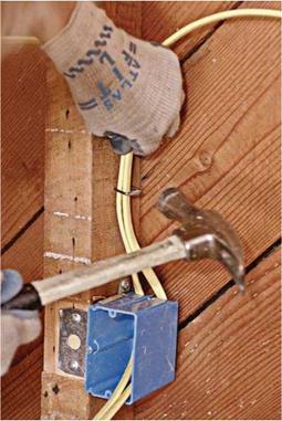
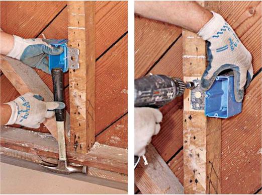
Box heights. There are few set rules about locat­ing boxes. Set the bottom of outlet boxes 12 in. above the subfloor, or use a hammer to approxi­mate box height, as shown in the top left photo on p. 244. In housing for disabled occupants, out­let box bottoms should be a minimum of 15 in. above the subfloor. For outlets over kitchen and bath counters, set the box bottoms 42 in. from the subfloor, so they’ll end up 8 in. above the counters and 4 in. above a standard 4-in.-high backsplash.

Locate wall switches on the lock side of a door (the side opposite the hinges). If you set the bot­toms of the switch boxes 44 in. or 48 in. above the subfloor, the box bottoms will align with the seam of a 48-in.-wide drywall panel installed horizontally—which means you’ll need to cut out only one panel. However, if a carpenter has added blocking at that height to nail the panel edges, raise the boxes till they clear the blocking.

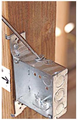
Mounting boxes. Mount boxes so they’ll be flush with finish surfaces. Most boxes have tabs or gauge marks stamped on the side to indicate dif­ferent surface thicknesses. If that’s not the case, hold a scrap of the finish material—for example, %-in. drywall—next to the front edge of the box as a depth gauge. Unless you’re installing nail-in boxes, use screws to mount the boxes so you can make adjustments if you need to. The depth of the Veco box shown on p. 244 can be adjusted after the drywall is up.

To attach ceiling boxes, you have these three choices: (1) screw the box directly to a joist;

(2) end-nail a piece of blocking between the

Use a hammer to set the box heights. This is much quicker than measuring, yet almost as accurate. Boxes will be roughly 12 in. above subfloors; set them 15 in. above the floor for disabled persons, if required.


Adjustable boxes can be raised or lowered till they’re flush with the finish walls. Here, the adjustment screw is visible below the electrician’s thumb. Note the bare wood under the mounting bracket: One pass of a power plane sets the brackets flush to the stud edges.


image487

Подпись: Drill holes at least 1 ft. above the boxes, so you can feed them with a gentle bend of the cable. Sharp bends can damage wires. joists, and screw the box to that; or (3) install an adjustable metal hanger bar between the joists, to which the box is mounted. Ceiling boxes must be secured to the structure, not merely to the fin­ish ceiling, so that the fixture will be adequately supported.