Category HIGHWAY ENGINEERING HANDBOOK

At-Grade Intersections

At-grade intersections should be designed to promote the safe movement of traffic on all legs with a minimal amount of delay to drivers using the intersection. The amount of delay a driver experiences is the measure of effectiveness for signalized intersections as used in capacity analysis. Factors to be considered in designing an intersection are:

• Traffic volumes on all legs, including separate counts for turning vehicles

• Sight distance

• Traffic control devices

• Horizontal alignment

• Vertical alignment

• Radius returns

• Drainage design

• Islands

• Left turn lanes

• Right turn lanes

• Additional through lanes

• Recovery areas

• Pedestrians

• Bicycles

• Lighting

• Development of adjacent property

Traffic Volumes. No intersection can be properly designed without first obtaining accurate traffic counts and reliable projections for the design year of the project. Traffic counts are best determined from actual field counts, including all turning movements, and are broken down by vehicle type. Vehicle types are divided into two groups. The first group includes passenger cars and type A commercial vehicles (pickup trucks and light delivery trucks not using dual tires). The second group includes type B commercial vehicles (tractor, semitrailer, truck-trailer combinations) and type C com­mercial vehicles (buses, dual-tired trucks with single or tandem rear axles). Adjustments are made to field counts to allow for day of the week, month of the year, time of day, and other site-related factors that may have a significant effect on the counts. Most urbanized areas have regional planning agencies that either provide or certify the traffic data used in intersection design.

Traffic Control. There are four basic types of traffic control at at-grade intersections:

• Cautionary, or nonstop, control

• Stop control for minor traffic

• Four-way stop control

• Signal control

In discussing at-grade intersections, the terms major roadway and minor roadway are sometimes used to distinguish between the two roads. The major roadway usually has a higher functional classification and a greater volume of traffic.

Cautionary, or nonstop, control is used only in special circumstances, such as at an entrance terminal on a freeway. Stop control for the minor roadway is one of the most common treatments found in practice. In these cases, the traffic volumes on the minor roadway are light enough that a signal is not required. The major roadway apparently has volumes low enough to allow gaps for the minor road traffic to enter or cross the intersection. Four-way stop control is effective in situations where the roadways have nearly equal traffic volumes but not great enough volume to justify installing a signal. Finally, signal control is used for intersections where volumes are large enough to preclude using one of the other types.

Sight Distance. Adequate sight distance is an important consideration when designing an at-grade intersection. The alignment and grade on the major roadway should, as a minimum, provide stopping sight distance as given in Table 2.2. The criteria for inter­section sight distance (Table 2.3) should also be met wherever possible. Figure 2.7 illustrates the lines of sight involved in intersection design.

Horizontal Alignment Considerations. It is best to avoid locating an intersection on a curve. Since this is often impossible, it is recommended that intersection sites be selected where the curve superelevation is 1/2 in/ft (22 mm/m) or less. It is also recom­mended that intersections be located where the grade on the major roadway is 6 per­cent or less, with 3 percent the desirable maximum. Intersection angles of 70° to 90° are provided on new or relocated roadways. An angle of 60° may be satisfactory if right-of-way is to be purchased for a future grade separation and the smaller angle will avoid reconstruction of the intersecting road. In such cases, it may be desirable to locate the intersection so the separation structure can be constructed in the future without disrupting the intersection operation.

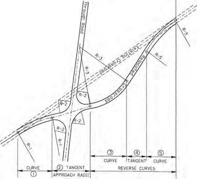
Relocation of the minor road is often required to meet the desired intersection location, to avoid roadway segments with undesirable vertical alignments, and to adjust intersection angles. Horizontal curves on the minor roads should be designed to meet the design speed of the road. The minor road alignment should be as straight as possible. Figure 2.31 shows the alignment for a typical rural crossroad relocation.

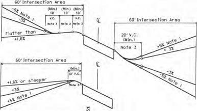
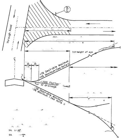
Vertical Alignment Considerations. On roadways with stop control at the intersec­tion, the portion of the intersection located within 60 ft (18 m) of the edge of the mainline pavement is considered to be the intersection area. The pavement surface within this intersection area should be visible to the driver within the limits of the mini­mum stopping sight distance listed in Table 2.2. By being able to see the pavement surface (height of object of zero), the driver (height of eye of 3.5 ft or 1.07 m) can observe the radius returns and pavement markings and recognize an approaching intersection. Figure 2.32 shows acceptable practice for design of the intersection area.

Combinations of pavement cross slopes and profile grades may produce unacceptable edge of pavement profiles in the intersection area. For this reason, edge of pavement profiles should be plotted and graphically graded to provide a smooth profile. Profile

At-Grade Intersections

Note 1. Curve—This portion of the crossroad can occur by itself at “T” type or three-legged intersections.

If possible, the radius of this curve should be commensurate with the design speed of the crossroad. Often, the length of the required profile controls the work length. The horizontal curvature is then chosen so it can be accomplished within this work length. Regardless of the length of the profile adjustment, it is desirable to provide at least a 230-ft (70-m) radius for this curve. When a 230-ft (70-m) radius incurs high costs, it is permissible to reduce this radius to a minimum of 150 ft (46 m).

Note 2. Tangent and Approach Radii—The crossroad in this area should have a tangent alignment. For the condition shown, the alignment between the radius returns is tangent from one side of the road to the other. However, at some intersections with a minor through movement (for example, crossroad intersections of standard diamond ramps) it may be desirable to provide different intersection angles on each side of the through road.

Note 3. Curve—The statements in (1) above also apply to this curve. With the reverse curve condition shown, the radius will often not exceed 250 ft (76 m) because flatter curves make the relocation extraordinarily long.

Note 4. Tangent—This tangent should be approximately 150 ft (46 m) in length for 30 or 40 mi/h (48 or 64 km/h) design speeds on the existing road, and approximately 250 ft (76 m) for 50 or 60 mi/h (80 or 97 km/h) design speeds. These lengths are generous enough to allow reasonable superelevation transitions between the reverse curves. In general, it is usually not desirable to make this tangent any longer than required. If a longer tangent can be used, the curvature or intersection angle can be improved and these two design items are more important.

Note 5. Curve—This curve should be much flatter than the other two curves. It should be capable of being driven at the normal design speed of the existing crossroad.

FIGURE 2.31 Typical rural crossroad relocation. (From Location and Design Manual, Vol. 1, Roadway Design, Ohio Department of Transportation, with permission)
At-Grade Intersections
Подпись: V.C.
Подпись: Minimum Stopping Sight Distance
Подпись: Grades and vertical Curves
Подпись: Note І. 5X maximum grades are permitted and
Подпись: 3.5'Height of Eye
Подпись: Si.Srodt tan9enf
Подпись: drain
Подпись: Mote з

At-Grade IntersectionsFIGURE 2.32 Crossroad profile for stop condition where through road has normal crown. Conversion: 1 ft = 0.305 m. (From Location and Design Manual, Vol. 1, Roadway Design, Ohio Department of Transportation, with permission)

grades within the intersection area for stop conditions are shown in Figs. 2.32 and 2.33. The grade outside the intersection area is controlled by the design speed of the cross­road. Normal design practices can be used outside the intersection area with the only restriction on the profile being the sight distance required as discussed above.

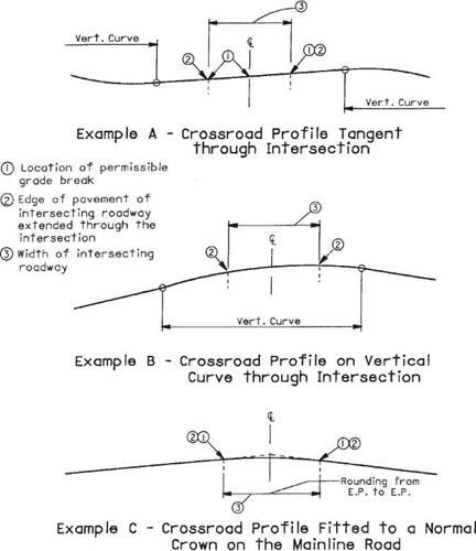
Grade breaks are permitted at the edge of the mainline pavement for a stop condi­tion. If these grade breaks exceed the limits given in note 3 of Fig. 2.32, they should be treated according to note 3 of Fig. 2.33. Several examples are shown in Fig. 2.33 of the use of grade breaks or short vertical curves adjacent to the edge of through pavement.

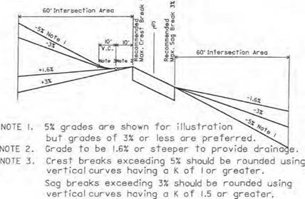
Signalized intersections require a more sophisticated crossroad profile. Whenever possible, roadway profiles through the intersection area of a signalized intersection should be designed to meet the design speed of the roads. Grade breaks at signalized

At-Grade Intersections

At-Grade Intersections

FIGURE 2.33 Crossroad profiles for stop condition where through road is superelevated. Conversion: 1 ft = 0.305 m. (From Location and Design Manual, Vol. 1, Roadway Design, Ohio Department of Transportation, with permission)

intersections should be in accordance with Table 2.17. Since the grade break across a normal crowned pavement is usually 3.12 percent, it should be noted that the crown must be flattened. This will allow vehicles on the crossroad to pass through the intersection on a green signal safely without significantly adjusting their speed. The sight distance requirements within the intersection area that were discussed for stop-controlled road­ways are also applicable for signalized intersections. Figure 2.34 shows examples of crossroad profiles through a signalized intersection.

Radius Returns at Intersections. Intersection radii in rural areas should normally be 50 ft (15 m), except lesser, but no less than 35 ft (11 m), radii may be used at minor

At-Grade Intersections

FIGURE 2.34 Examples of crossroad profiles through signalized intersection. (From Location and Design Manual, Vol. 1, Roadway Design, Ohio Department of Transportation, with permission)

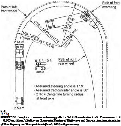
intersecting roads if judged appropriate for the volume and character of turning vehi­cles. Radii larger than 50 ft (15 m), a radius with a taper, or a three-center curve should be used at any intersection where the design must routinely accommodate semitrailer truck turning movements. Truck turning templates should be used to deter­mine proper radii and stop bar location. Figure 2.35 shows an example of a turning template for a WB-50 semitrailer truck. Complete sets of turning templates may be obtained from the Institute of Traffic Engineers (Ref. 12). Also available for use with CAD drawings is a CAD-based software product called AutoTURN which is available from Transoft Solutions (Ref. 16). When used in applications with CAD drawings, it reproduces the turning paths for a wide variety of design vehicles. When truck turning

12.95 m [42.5 ft] Trailer

Подпись:

templates are used, a 2-ft (0.6-m) clearance should be provided between the edge of pavement and the closest tire path.

Corner radii at street intersections in urban areas should consider the right-of-way available, the intersection angle, pedestrian traffic, approach width, and number of lanes. The following should be used as a guide:

• Radii of 15 to 25 ft (4.6 to 7.6 m) are adequate for passenger vehicles and may be provided at minor cross streets where there are few trucks or at major intersections where there are parking lanes.

• Radii of 25 ft (7.6 m) or more should be provided at minor intersections on new or reconstruction projects where space permits.

• Radii of 30 ft (9.1 m) or more should be used where feasible at major cross street intersections.

• Radii of 40 ft (12.2 m) or more, three-centered compound curves, or simple curves with tapers to fit truck paths should be provided at intersections used frequently by buses or large trucks.

Drainage Considerations. Within the intersection area, the profile of the crossroad should be sloped wherever possible so the drainage from the crossroad will not flow across the through road pavement. For a stop condition, the 10 ft (3.0 m) of crossroad profile adjacent to the through pavement is normally sloped away from the through pavement, using at least a 1.56 percent grade, as shown in Fig. 2.32. The profiles of curbed radius returns within the intersection may be adjusted to accommodate location of catch basins. It is recommended that exaggerated profiles be used to make adjust­ments. To ensure smooth transitions around the returns, plot the pavement edges for at least 25 ft (7.6 m) going away from the returns for each leg of the intersection.

Islands at Intersections. In intersection design, an island is defined as an area between traffic lanes that has been delineated to control traffic movements through the intersection. An island may be curbed or uncurbed. It may be concrete, grass, or the same material as the traffic lanes. Islands may be used at intersections for the following reasons:

• Separation of conflicts

• Control of angle of conflict

• Reduction in excessive pavement areas

• Favoring a predominant movement

• Pedestrian protection

• Protection and storage of vehicles

• Location of traffic control devices

Although certain situations require the use of islands, they should be used sparingly and avoided wherever possible. Curbed islands are most often used in urban areas where traffic is moving at relatively low speeds, 40 mi/h (64 km/h) or less, and fixed-source lighting is available. Curbed islands with an area smaller than 50 ft2 (4.6 m2) in urban locations and 75 ft2 (7.0 m2) in rural areas should generally not be used. An area of 100 ft2 (9.3 m2) is preferred in either case. Where pedestrian traffic will be using curbed islands, the islands must be provided with curb ramps. Islands delineated by pavement markings are often preferred in rural or lightly developed areas, when approach speeds are rela­tively high, where there is little pedestrian traffic, where fixed-source lighting is not provided, or where traffic control devices are not located within the island. Nonpaved islands are normally used in rural areas. They are generally turf and are depressed for drainage purposes.

Left Turn Lanes. Probably the single item having the most influence on intersection operation is the treatment of left-turning vehicles. Left turn lanes are generally desirable at most intersections. However, cost and space requirements do not permit their inclu­sion in all situations. Intersection capacity analysis procedures should be used to determine the number and use of all lanes. Left turn lanes are generally required under two conditions: (1) when left turn design volumes exceed 20 percent of total directional approach design volumes, and (2) when left turn design volumes exceed 100 vehicles per hour in peak periods.

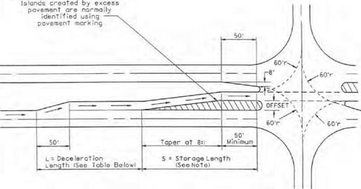
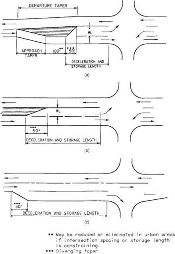
Opposing left turn lanes should be aligned opposite each other because of sight distance limitations. They are developed in several ways depending on the available width between opposing through lanes. Figure 2.36a shows the development required when additional width must be generated. The additional width is normally accomplished by widening on both sides. However, it could be done all on one side or the other. In Fig. 2.36b, the median width is sufficient to permit the development of the left turn lane. Figure 2.37 shows the condition where an offset left turn lane is required to obtain adequate sight distance in wide medians.

In developing turn lanes, several types of tapers may be involved as shown in Fig. 2.36:

Approach taper. An approach taper directs through traffic to the right. Approach taper lengths are calculated using Eq. (2.5) or (2.6).

Departure taper. The departure taper directs through traffic to the left. Its length should not be less than that calculated using the approach taper equations. Normally, however, the departure taper begins opposite the beginning of the full-width turn lane and continues to a point opposite the beginning of the approach taper.

Diverging taper. The diverging taper is the taper used at the beginning of the turn lane. The recommended length of a diverging taper is 50 ft (15 m).

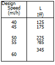
Tables 2.26 and 2.27 have been included to aid in determining the required lengths of left turn lanes at intersections. After determining the length of a left turn lane (Table 2.26), the designer should also check the length of storage available in the adjacent through lane(s) to ensure that access to the turn lane is not blocked by a backup in the through lane(s). To do this, Table 2.27 may be entered using the average number of through vehicles per cycle, and the required length read directly from the table. If two or more lanes are provided for the through movement, the length obtained should be divided by the number of through lanes to determine the required storage length.

It is recommended that left turn lanes be at least 100 ft (30 m) long, and the maxi­mum length be no more than 600 ft (183 m). The width of a left turn lane should desirably be the same as the normal lane widths for the facility. A minimum width of 11 ft (3.4 m) may be used in moderate – and high-speed areas, while 10 ft (3.0 m) may be provided in low-speed areas. Additional width should be provided whenever the lane is adjacent to a curbed median as discussed previously under “Position of Curb.”

Double Left Turn Lanes. Double left turn lanes should be considered at any signalized intersection with left turn demands of 300 vehicles per hour or more. The actual need should be determined by performing a signalized intersection capacity analysis. Fully protected signal phasing is required for double left turns. When the signal phasing permits

At-Grade Intersections

FIGURE 2.36 Turning lane designs showing roadway taper. (a) Left turn lane with no median or median width less than WL. (b) Left turn lane with median wider than WL. (c) Right turn lane. Conversions: 50 ft = 15 m, 100 ft = 30 m. (From Location and Design Manual, Vol. 1, Roadway Design, Ohio Department of Transportation, with permission)

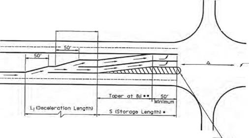
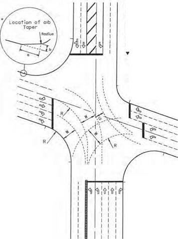
simultaneous left turns from opposing approaches, it may be necessary to laterally offset the double left turn lanes on one approach from the left turn lane(s) on the opposing approach to avoid conflicts in turning paths. Figure 2.38 provides an example. All turning paths of double left turn lanes should be checked with truck turning templates allowing 2 ft (0.6 m) between the tire path and edge of each lane. Expanded throat widths are necessary for double left turn lanes as illustrated in Fig. 2.39.

Подпись: 158At-Grade Intersections

Подпись:NOTE

I. Determine о minimum length for S by multiplying 8 times The lot era I offset and adding 50 ft.

Using the design Turninq volume, obtain the required storage length from Table 2.26. Use the greater of these^ two numbers for L2. If the length from ТаЫе2.26 is the greater value, increase the tangent area at the intersection.

TABLE 2.26 Determination of Length of Left Turn Lanes

Type of

traffic control

Turn demand volume for design speed, mi/h

30-

-35

40-

-45

50-

-60

High

Low*

High

Low*

High

Low*

Signalized

A

A

B or C

B or C

B or C

B or C

Unsignalized stopped crossroad

A

A

A

A

A

A

Unsignalized through road

A

A

C

B

B or C

B

Conversions: 1 mi/h = 1.609 km/h, 1 ft = 0.305 m.

Condition A: storage only:

Length = 50 ft (diverging taper) + storage length Condition B: high-speed deceleration only:

Design speed, mi/h Length (including 50-ft diverging taper), ft

40

125

45

175

50

225

55

285

60

345

Condition C: moderate-speed deceleration and storage:

Design speed, mi/h

Length (including 50-ft diverging taper)

40

111

45

125

50

143

+ storage length

55

164

60

181 ,

*Low is considered 10% or less of approach traffic volume.

^Whichever is greater.

Source: Location and Design Manual, Vol. 1, Roadway Design, Ohio Department of Transportation,

with permission.

Right Turn Lanes. Exclusive right turn lanes are less critical in terms of safety than left turn lanes. However, right turn lanes can significantly improve the level of service of signalized intersections. They also provide a means of safe deceleration for right­turning traffic on high-speed facilities and separate right-turning traffic from the rest of the traffic stream at stop-controlled or signalized intersections. As a general guideline, an exclusive right turn lane should be considered when the right turn volume exceeds 300 vehicles per hour per lane.

Figure 2.36c shows the design of right turn lanes. Table 2.27 may be used in prelimi­nary design to estimate the storage required at signalized intersections. The recom­mended maximum length of right turn lanes at signalized intersections is 800 ft (244 m), with 100 ft (30 m) the minimum length.

The blockage of the right turn lane by the through vehicles should also be checked using Table 2.27. With right-turn-on-red operation, it is imperative that access to the right turn lane be provided to achieve full utilization of the benefits of this type of operation.

The width of right turn lanes should desirably be equal to the normal through lane width for the facility. In low-speed areas, a minimum width of 10 ft (3.0 m) may be provided. Additional lane width should be provided when the right turn lane is adjacent to a curb.

TABLE 2.27 Storage Length at Intersections

Average no. of vehicles per cycle*

Required length, ft

Required length, m

Average no. of vehicles per cycle*

Required length, ft

Required length, m

1

50

15

17

600

183

2

100

30

18

625

190

3

150

46

19

650

198

4

175

53

20

675

206

5

200

61

21

725

221

6

250

76

22

750

229

7

275

84

23

775

236

8

325

99

24

800

244

9

350

107

25

825

251

10

375

114

30

975

297

11

400

122

35

1125

343

12

450

137

40

1250

381

13

475

145

45

1400

427

14

500

152

50

1550

472

15

525

160

55

1700

518

16

550

168

60

1850

564

*Average vehicles/cycle = [DHV (turning lane)]/(cycles/hour)

If cycles/hour are unknown, assume:

Unsignalized or 2-phase—60 cycles per hour

3-phase—40 cycles per hour

4-phase—30 cycles per hour

Source: Location and Design Manual, Vol. 1, Roadway Design, Ohio Department of Transportation,

with permission.

Double Right Turn Lanes. Double right turn lanes are rarely used. When they are justified, it is generally at an intersection involving either an off-ramp or a one-way street. Double right turn lanes require a larger intersection radius [usually 75 ft (23 m) or more] and a throat width comparable to a double left turn (Fig. 2.39).

Additional Through Lanes. Normally, the number of through lanes at an intersection is consistent with the number of lanes on the basic facility. Occasionally, through lanes are added on the approach to enhance signal design. As a general suggestion, enough main roadway lanes should be provided that the total through plus turn volume does not exceed 450 vehicles per hour per lane.

Recovery Area at Curbed Intersections. When a through lane becomes a right-turn – only lane at a curbed intersection, an opposite-side tapered recovery area should be considered. The taper should be long enough to allow a trapped vehicle to escape, but not so long as to appear like a merging lane. Taper lengths may vary from 200 to 250 ft (61 to 76 m) depending on design speed.

Pedestrians. Whenever sidewalks approach a curbed intersection, curb ramps must be provided, lining up with the crosswalks. At signalized intersections, when pedestrians are moving concurrently with traffic on one of the phases, sufficient time must be provided on the phase to allow pedestrians to cross the intersection. This is especially significant on intersections with large radii or multiple through lanes. There may be situations where pedestrian volumes will require a separate phase of the signal to be dedicated to their passage.

Islands created by excess pavement are normally Identified using pavement marking

Подпись:Подпись:Подпись: шшПодпись: (See Table Below)At-Grade IntersectionsПодпись:* Use Table 2.27 to determine storage length. For offset left turn lanes, minimum storage length equals 8 x offset + 50′.

Taper Is used when duolleft turn lanes are offset.

д If opposite approach hos one left turn lane, these lanes should line up.

FIGURE 2.38 Layout for double left turn lanes with lateral offsets. Conversions: 1 mi/h = 1.609 km/h, 1 ft = 0.305 m. {From Location and Design Manual, Vol. 1, Roadway Design, Ohio Department of Transportation, with permission)

A= mostly "P* vehicles, some *SU’ trucks

Подпись:Подпись:At-Grade Intersections

Подпись: INSIDE RADIUS R («) EXPANDED THROAT WIDTH W (ft) DESIGN TRAFFIC CONDITIONS A 0 c 50 31 36 45 75 29 33 38 IOO 28 31 35 150 28 29 32 200 26 28 30

B= sufficient *SU* trucks to govern design, some semitrailers

C= sufficient bus and combi­nation types to govern design

Generally, A is when T < 5X В is when T * 5-Ю»

C is when T > ЮX T= percentage of type В and C trucks in Design AOT

F = (W – 24)/2

F

a

b

<2.0

0

0

2.0-3.9

40

4

4.0-5.9

45

6

6.0-9.0

50

8

Other Considerations. On designated bikeway routes, bicycles may have their own lane approaching the intersection. This will require special handling in cases where right-turning vehicles may be crossing the path of through bicycle traffic. The designer should consult with a bicycle facility design reference before proceeding with the intersection design.

Providing fixed-source lighting at intersections, especially in urban areas, is always a safety benefit to drivers. It is particularly important for large-area intersections and channelized intersections, since turning paths may be difficult to determine at night.

The development of adjacent property can sometimes have a detrimental effect on intersection design, since driveways accessing the development may be located too close to the intersection. Whenever possible, accesses to adjacent properties should be located far enough from the intersection so as not to interfere with turn lane design.

. INTERSECTION DESIGN

An intersection is defined as an area where two or more roadways join or cross. Each roadway extending from the intersection is referred to as a leg. The intersection of two roadways has four legs. When one roadway ends at the intersection with another roadway, a three-leg intersection, or T intersection, is formed. Some intersections have more than four legs, but this design should be avoided, since the operation of traffic movements
is usually inefficient. There are three general types of intersections: (1) at-grade, where two or more roadways cross in the same vertical plane, (2) grade-separated, where one roadway is bridged over or tunneled under the other roadway but no turning movements are allowed, and (3) interchanges, a special type of grade-separated intersection where turning movements are accommodated by ramps connecting the two roadways.

Pedestrian Facilities

When pedestrian facilities are to be constructed or reconstructed as part of project plans, the facilities should be designed to accommodate the disabled. Guidance in design of pedestrian facilities with access for the disabled is available (Ref. 11).

Walks. Walks should be provided in urban areas where pedestrian traffic currently exists or is planned in the future. Walks may be provided in rural areas where they will have sufficient use in relation to cost and safety. Walks are usually made of concrete, although asphalt or gravel may be used under special circumstances. Concrete walks are usually 4 in (100 mm) thick. At drive locations, the thickness is increased to 6 in (150 mm), or the drive thickness, whichever is greater. Asphalt or gravel walks are mostly used in parks, rest areas, etc., where there is low usage. Asphalt walks consist of 2 in (50 mm) of asphalt and 5 in (250 mm) aggregate base, while gravel walks are con­structed of 4 in (100 mm) compacted aggregate base.

Walk Design. The normal width of walks is 4 ft (1.2 m) for residential areas and 6 ft (1.8 m) for commercial areas or major school routes. In downtown areas, the walk width normally extends from the curb to the right-of-way or building line. Transverse slopes should be 1/4 in/ft (21 mm/m). The grade of the walk is normally parallel to the curb or pavement grade, but may be independent. The walk and the “tree lawn” (see next section) normally slope toward the pavement. Care should be taken in setting the pavement curb grade so that the sidewalk and the curb will not trap water or otherwise preclude usability of the adjoining property. The back edge of the walk should be located 2 ft (0.6 m) inside the right-of-way line, unless grading, utilities, or other considera­tions require a greater dimension.

Tree Lawn. The tree lawn is defined as the area between the front of the curb and the front edge of the sidewalk. Grass is usually provided in the tree lawn, although in some urban areas the tree lawn is paved. As shown in Fig. 2.30, in most cases, the desirable tree lawn width is 8 ft (2.4 m) or more. The 8-ft (2.4 m) width provides an area for snow storage and for traffic signs, and an adequate distance for elevation changes at drives. Tree lawn widths of less than 5 ft (1.5 m) result in locating of sign­posts close to pedestrians using the walk, and steep grades on drive profiles. The mini­mum tree lawn width is 2 ft (0.6 m).

Border Area. In an urban area where a walk is not provided, the area between the face of curb and the right-of-way line is often referred to as a border. As indicated in Fig. 2.30d, the border width in residential areas should be at least 8 ft (2.4 m) and preferably 14 ft (4.3 m). In commercial areas, the minimum border width is 10 ft (3.0 m), while a 16-ft (4.9-m) width is preferable.

Walks on Bridges. Walks should be provided on bridges located in urban or suburban areas having curbed sections under two conditions: (1) where there are existing walks on the bridge and/or bridge approaches, or (2) where evidence can be shown through local planning processes, or similar justification, that walks will be required in the near future (5 to 10 years). Anticipated pedestrian volumes of 50 per day justify a walk on one side, and 100 per day justify walks on both sides. Walks on bridges should preferably be 6 ft (1.8 m) wide in residential areas and 8 ft (2.4 m) wide in commercial areas measured from the face of curb to face of parapet. Widths, however, may be as much as 12 ft (3.7 m) in downtown areas. The minimum bridge walk width is 5 ft (1.5 m).

Walks under Bridges. The criterion for providing walks at underpasses is basi­cally the same as described above for walks on bridges. An exception is that in areas where there are no approach walks, space will be provided for future walks but walks will not be constructed with the project unless there is substantial con­current approach walk construction. Where the approach walks at underpasses include a tree lawn, the tree lawn width may be carried through the underpass wherever space permits.

Curb Ramps. A curb ramp is a portion of the walk that is modified to provide a gradual elevation transition through the face of the adjoining curb. It is designed to provide safe and convenient curb crossings for the disabled in wheelchairs, but it can also be used by others. Examples include wheeled vehicles maneuvered by pedestrians and bikeway traffic, when such use is permitted. Curb ramps should be provided where curb and walks are being constructed at intersections and other major points of pedestrian curb crossing such as mid-block crosswalks. When a curb ramp is built on one side of a street, a companion curb ramp is required on the opposite side of the street. The basic requirement is that a crosswalk must be accessible via curb ramps at both ends, not one end only. In most cases, curb ramps will be installed in all quadrants of an intersection. Curb ramps should be located within crosswalk markings to permit legal street crossings. The ramp location must be coordinated with drainage structures, utility poles, etc. The normal gutter profile should be continued through the ramp area, except the profile may be altered to avoid a location conflict between the ramp and a drainage structure. Drainage structures should not be located in the ramp or in front of the ramp. Catch basins should be placed upstream from the ramp.

Curbs

The type of curb and its location affect driver behavior patterns, which, in turn, affect the safety and utility of a road or street. Curbs, or curbs and gutters, are used mainly in urban areas. They should be used with caution where design speeds exceed 40 mi/h (64 km/h). Following are various reasons for justifying the use of curbs, or curbs and gutters:

• Where required for drainage

• Where needed for channelization, delineation, control of access, or other means of improving traffic flow and safety

• To control parking where applicable

Types of Curb. There are two general categories of curbs: barrier curbs and mount­able curbs. Barrier curbs are relatively high [6 in (0.15 m) or more] and steep-faced. Mountable curbs are 6 in (0.15 m) or less in height and have flatter, sloping faces so that vehicles can cross them with varying degrees of ease. Figure 2.29 (Ref. 14) shows various curb designs that are commonly used on roadways. Types 1, 3, and 4 are examples of mountable curbs and are used for channelizing traffic, especially in islands and medians. Types 2 and 6 are barrier curbs used along pavement edges in urban areas and are designed to handle drainage more efficiently. Types 7 and 8 are tall barrier curbs designed to provide a more positive traffic barrier than the others. Type 7 is used as an alternate for guiderail in low-speed urban situations.

Position of Curb. Curbs are normally used at the edge of pavement on urban streets where the design speed is 40 mi/h (64 km/h) or less. Curbs at the edge of pavement have an effect on the lateral placement of moving vehicles. Drivers tend to shy away from them. Therefore, all curbs should be offset at least 1 ft (0.3 m) and preferably 2 ft (0.6 m) from the edge of the traffic lane. Where curb and gutter are used, the standard gutter width is 2 ft (0.6 m).

On roads where the design speed exceeds 40 mi/h (64 km/h), curbs should be used only in special cases. Special cases may include, but are not limited to, the use of curb to control surface drainage or to reduce right-of-way requirements in restricted areas.

Curbs

Edge of groded shoulder Portion of volley In depressed aiedl<


‘-B


Treoted Shoulder


Подпись: 143

СгомоV#r povement Slope t as mo In По* profile.


SECTION Д-Д


Dimensions Applicable toVarying Median Demands

M, ft

D, in

R-l, ft

R-2, ft

84

17.25

24.87

55.20

60

11.50

16.31

35.24

50

9.13

12.73

26.93

40

6.75

9.16

18.61


0.04


0.04


Tv-Ospresslon


ДВДЕ


J


Curbs

SECTION B-B


CurbsCurbs

Curbs

FIGURE 2.28 Design for U-turn median opening. Conversion: 1 ft = 0.305 m. (From Location and Design Manual, Vol. 1, Roadway Design, Ohio Department of Transportation, with permission)

Curbs

‘Asphalt’concrete [ Base J


TYPE /


• Bull Joints shell be provided between combined cu/b-and-guller and new rigid pavements. with lit bars or hoot bolts provided at five foot Intervals. Combined curb-ond-gutter shell be tied to existing rigid pavements wllh expansion hoot bolls spaced at five foot Intorvols. if the combined curb-ond-gulfer adjoins a new rigid base or on existing rigid base or povemeni that Is to be surfoced with bituminous malerlol. a bull Jolnl shall be provided and tie bars.’hoot bolls or expansion hoot bolls shall be omitted.


TYPE 5


TYPE 2


TYPE 4


Подпись: 144
Curbs

CurbsCurbsCurbs

When it is necessary to use curbs on roads where the design speed is over 40 mi/h, they should not be closer to the traffic than 4 ft (1.2 m) or the edge of the treated shoulder, whichever is greater.

Curb/Guiderail Relationship. If curbs are used in conjunction with guiderail on roads having a design speed in excess of 40 mi/h (64 km/h), the face of curb should preferably be located either at or behind the face of guiderail. Under no conditions should the face of curb be located more than 9 in (0.23 m) in front of the face of rail. This restriction is necessary to prevent a vehicle from “vaulting” over the rail or strik­ing it too high to be contained. Although guiderail is not normally used on curbed roadways having design speeds of 40 mi/h (64 km/h) or less, the same criteria used for higher-speed roadways should apply. Where this is not feasible or practical, the curb may be placed in front of the rail. Regardless of the design speed of the roadway or the placement of the curb, the face of guiderail should not be located closer than 4 ft (1.2 m) to the roadway.

Curb Transitions. Curb and raised median beginnings and endings should be tapered from the curb height to 0 in (0 m) in 10 ft (3 m). When an urban-type section with curbs at the edge of pavement changes to a rural-type section without curbs, the curb should be transitioned laterally at a 4:1 (longitudinal:lateral) rate to the outside edge of the treated shoulder, or 3 ft (0.9 m), whichever is greater. When a curbed side road intersects a mainline that is not curbed, the curb should be terminated no closer to the mainline edge of pavement than 8 ft (2.4 m) or the edge of the treated shoulder of the mainline, whichever is greater.

Interchange Elements

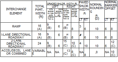
Cross-section information pertaining to interchange elements, such as ramps and directional roadways, is given in Fig. 2.26. This information includes pavement and shoulder dimensions for acceleration-deceleration lanes, one – and two-lane directional roadways, and medians between adjacent ramps. Notice that for a single-lane ramp, the shoulder and guiderail offset distances are greater on the driver’s right-hand side than on the left. This is to provide more width for drivers to pull over in emergencies and to allow people a better opportunity to go around disabled vehicles.

2.3.2 Medians

A median is a desirable element on all streets or roads with four or more lanes. The principal functions of a median are to prevent interference of opposing traffic, to provide a recovery area for out-of-control vehicles, to provide areas for emergency stopping and left turn lanes, to minimize headlight glare, and to provide width for future lanes. A median should be highly visible both day and night and in definite contrast to the roadway.

Width. The width of a median is the distance between the inside edges of the pave­ment. See Fig. 2.27 for examples of various medians. The width depends upon the type of facility, topography, and available right-of-way. In rural areas with flat or rolling terrain, the desirable median width for freeways is 60 to 84 ft (18 to 26 m). Although the minimum median width is normally 40 ft (12 m), narrower medians may be used in rugged terrain. A constant-width median is not necessary, and in fact,

Lateral clearances, ft


Vertical clearance over surfaced roadway, ftc


On bridgea


Traffic

Design year
ADT


Rural


Under bridge^7


Functional

class


Urban,

minimum


Preferred


Minimum


Minimum


Preferred


Minimum


Preferred


Interstates,

All

Right, 12а’

Right, 14^g

Freeways and

Left, ¥■•

Left, 6

expressways

Arterial s

> 4000

W

12

2001-4000

¥

10

1001-2000

&>

8

400-1000

&’

8

< 400

4

6

Collectors

> 4000

8"’

10

2001-4000

4 m

8

1001-2000

4?я, я

6

400-1000

4»г, я

4

< 400

4 m, o

4

Locals

> 4000

8"’

10

2001-4000

3

8

1001-2000

3

6

400-1000

3

4

< 400

2

4


16.5й


17.0


.Й л

£ п


16.5й


17.0


•9

H

л

<3

43

3

о


00 О

К, 8


Подпись: 138

14.5


15.0


Interchange Elements


14.5


15.0


и


Conversion: 1 ft = 0.305 m.

"Distance measured from edge of the traveled lane to face of curb or railing if no curb is provided.

^Distance measured from edge of traveled lane to face of walls or abutments and piers.

cTo minimize structure cost, design tolerances for clearances are plus 4 in, minus 0 in. Sign supports and pedestrian structures have a 1 – ft additional clearance. Clearances shown are over paved shoulder as well as pavement width.

dli bridge is considered to be a major structure having a length of 200 ft or more, the width may be reduced, subject to economic studies, but to no less than 4 ft.

eWhere the truck DDHV is 250 or less, may be reduced 2 ft.

/Where the truck DDHV is 250 or less, the right shoulder width may be reduced 2 ft.

AVhere concrete barrier is used on the approach slabs or in advance of the bridge, the preferred shoulder width will equal the minimum shoulder width.

hA 16.5-ft minimum vertical clearance applies to all rural sections and the single designated route in urban areas. On other urban routes, not on the single designated route, the vertical clearance should not be less than 15.5 ft.

‘If 6 or more lanes, provide 12 ft width. Where truck DDHV is 250 or less, the left shoulder bridge width may be reduced by 2 ft.

;If 6 or more lanes, provide 14 ft width. Where the truck DDHV is 250 or less, the left width may be reduced 2 ft.

Подпись: 139*In locations with restricted right-of-way, may be reduced to a clearance of 8.0 ft right side, 4.5 ft median side, plus barrier clearance, except where footnote l applies.

гМау be reduced to a clearance of 2 ft plus barrier clearance on urban streets with restricted right-of-way and a design speed less than 50 mi/h (80 km/h).

mMay be З-ft width if bridge length exceeds 100 ft.

ftMay be З-ft width if turf shoulder is used.

°May be 2-ft width if turf shoulder is used.

?Clear zone width is defined in Art. 6.2.

Source: Location and Design Manual, Vol. 1, Roadway Design, Ohio Department of Transportation, with permission.

(A)

Подпись: INTERCHANGE ELEMENT TOTAL PVMT. WIDTH (ft) GRADED SHLDR. WIDTH (ft) PAVED SHLDR WIDTH (ft) NORMAL ROUNDING (ft) (D) NORMAL BARRIER OFFSET LEFT RIGHT WITH BARRIER OR rQRE- SL0PE STEEPER THAN &: w/o BARRIER SLOPES 6!! OR FLATTER WITH BARRIER OR r0RE~ SLOPE STEEPER THAN 6t w/o BARRIER SLOPES 6:1 OR FLATTER LT RT LT RT RAMP 16 (A) 9 (B) 6 и (B) 8 3 6 10 6 8 l-LANE DIRECTIONAL ROADWAY 16 (A) 9 (B) 6 и (B) 8 A 6 10 6 8 2-LANE DIRECTIONAL ROADWAY 24 9 (B) 6 15 (C) 10 (C) 4 10 10 6 12 (C) ACCEL/DECEL LANE OR COMBINED VARIABLE NA NA 13 (C) 8 (C) NA 8 ,0 NA 10 (C)

Use 18′ when inside pavement edge radius is less than 200′.

(B) May be reduced Г if the face of the mainline barrier is 2′ from the outside edge of fhe graded shoulder.

(C) Or match mainline dimension if lesser.

(D) Rounding is 4′ when barrier is used. No rounding is required when foreslope is 6:1 or flatter.

TWO-WAY RAMP MEDIAN

Roundi ng

Interchange Elements

MINIMUM TWO-WAY RAMP MEDIAN

FIGURE 2.26 Cross-section information for interchange elements—pavement, shoulders, and medians. Conversion: 1 ft = 0.305 m. (From Location and Design Manual, Vol. 1, Roadway Design, Ohio Department of Transportation, with permission) variable-width medians and independent profiles may be used for the two roadways. Narrow medians with a barrier (barrier medians) are normally used in urban areas. Under normal design, the median width will vary depending on the width of the barrier and the shoulder width required (Table 2.23).

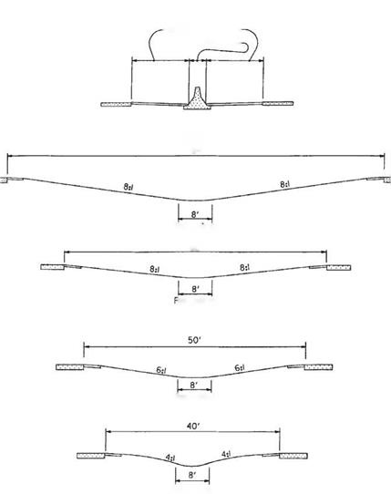
Types. Medians are divided into types depending upon width and treatment of the median area and drainage arrangement. In general, raised or barrier medians are applic­able to urban areas, while wide, depressed medians apply to rural areas. Figure 2.27 shows examples. Medians in rural areas are normally depressed to form a swale in the center and are constructed without curbs. The type of median used in an urban area

Interchange ElementsBARRIER MEDIAN

—Shoulder Width – Barrier Width —

DEPRESSED MEDIANS

84′

Rounding
60′
loundlng

Rounding

Rounding

FIGURE 2.27 Typical designs for medians. Conversion: 1 ft = 0.305 m. (From Location and Design Manual, Vol. 1, Roadway Design, Ohio Department of Transportation, with permission) depends on the traffic volume, speed, degree of access, and available right-of-way. On major streets with numerous business drives, a median consisting of an additional lane, striped as a continuous two-way left turn lane, is appropriate. A solid 6-in-high (0.15-m) lane concrete median may be used in low-speed areas (where the design speed is 40 mi/h (64 km/h) or less) and where an all-paved section is desired and a wider median cannot be justified. Barrier medians are normally recommended for urban facilities when the design speed is over 40 mi/h (64 km/h). However, care must be
exercised when barrier medians are used on expressways with unsignalized at-grade intersections because of sight distance limitations and end treatments of the barrier.

U-Turn Median Openings. U-turn median openings may be provided on express­ways, freeways, or interstate highways with nonbarrier medians where space permits and there is a need. U-turns may be needed for proper operation of police and emer­gency vehicles, as well as for equipment engaged in physical maintenance, traffic service, and snow and ice control. U-turn crossings should not be constructed in barrier-type medians. When U-turn median openings are permitted, it is intended they be spaced as close to 3-mi (4.8-km) intervals as possible. Crossings should be located at points approximately 1000 ft (305 m) beyond the end of each interchange speed change lane.

An example of a typical U-turn median opening is shown in Fig. 2.28, which indi­cates geometric features applicable to crossings located in medians of widths ranging from 40 to 84 ft (12 to 26 m). Turning radius should be modified proportionately for medians of varying widths. Tapers should be 200 ft (61 m) in length for all median widths. The profile grade line should normally be an extension of the cross slope of the shoulder paving, rounded at the lowest point.

Grading and Side Slopes

This section is concerned with the design of the slopes, ditches, parallel channels, and interchange grading. It incorporates into the roadside design the concepts of vehicular safety developed through dynamic testing. Designers are urged to consider flat foreslopes and backslopes, wide gentle ditch sections, and elimination of barriers.

Slopes. Several combinations of slopes and ditch sections may be used in the grading of a project. Details and use of these combinations are discussed in subsequent paragraphs. In general, slopes should be made as flat as possible to minimize the necessity for barrier protection and to maximize the opportunity for a driver to recover

TABLE 2.24 Recommended Pavement Widening on Horizontal Curves, ft, for WB-50 Design Vehicles

Degree of curve

Pavement width on tangent, ft

24

22

20

Design speed, mi/h

Design speed, mi/h

Design speed, mi/h

30

to

39

40

to

49

50

to

59

60

to

69

70

and

over

30

to

39

40

to

49

50

to

59

60

and

over

30

to

39

40

to

49

50

to

59

60

and

over

1°00′

0

0

0

0

0

1.0

1.0

1.0

1.0

1.5

2.0

2.0

2.0

2°00′

0

0.5

0.5

0.5

0.5

1.0

1.5

1.5

1.5

2.0

2.5

2.5

2.5

3°00′

0.5

1.0

1.0

1.0

1.0

1.5

2.0

2.0

2.0

2.5

3.0

3.0

3.0

4°00′

1.0

1.0

1.5

1.5

1.5

2.0

2.0

2.5

2.5

3.0

3.0

3.5

3.5

5°00′

1.5

1.5

2.0

2.5

2.5

3.0

3.0

3.0

3.5

3.5

4.0

4.0

6°00′

2.0

2.0

2.5

2.5

3.0

3.0

3.5

3.5

3.5

4.0

4.5

4.5

7°00′

2.0

2.0

3.0

3.0

3.5

4.0

4.0

4.5

5.0

8°00′

2.5

3.0

3.0

3.5

4.0

4.0

4.5

5.0

5.0

9°00′

3.0

3.0

3.5

4.0

4.0

4.5

5.0

5.0

5.5

10°00′

3.0

3.5

4.0

4.5

5.5

5.5

11°00′

3.5

4.0

4.5

5.0

5.5

6.0

12°00′

4.0

4.0

5.0

5.0

6.0

6.0

13°00′

4.0

4.0

5.0

5.0

6.0

6.0

14°00′

4.5

4.5

5.5

5.5

6.5

6.5

14°30′

4.5

5.0

5.5

5.5

6.5

6.5

15°00′

5.0

6.0

7.0

18°00′

5.5

7.0

7.5

19°00′

6.0

7.0

8.0

21°00′

6.5

7.5

8.5

22°00′

6.5

7.5

8.5

25°00′

7.5

8.5

9.5

26°00′

7.5

8.5

8.5

26°30′

8.0

9.0

10.0

Conversions: 1 mi/h = 1.609 km/h, 1 ft = 0.305 m.

Note: Values less than 2.0 ft may be disregarded. Multiply table values by 1.5 for three lanes and by 2.0 for four lanes.

Source: Location and Design Manual, Vol. 1, Roadway Design, Ohio Department of Transportation,

with permission.

control of a vehicle after leaving the traveled way. Regardless of the type of grading used, projects should be examined in an effort to obtain flat slopes at low costs. For example, fill slopes can be flattened with material that might otherwise be wasted, and backslopes can be flattened to reduce borrow.

To better understand the various types of grading, it is necessary to become familiar with the concept of a clear zone. Clear zone is defined as the unobstructed, relatively flat area provided beyond the edge of the traveled way for the recovery of errant vehicles and includes any shoulders or auxiliary lanes (Ref. 1, 2). Chapter 6 discusses the road­side safety aspects of designing for the clear zone, including the use of barriers to shield objects in the clear zone. In the following paragraphs, four types of roadside grading are described. The designer must select the appropriate one for the roadway being designed.

Grading and Side Slopes

Safety grading is the shaping of the roadside using 6:1 or flatter slopes within the clear zone area, and 3:1 or flatter foreslopes and recoverable ditches beyond the clear zone. Safety grading is used on interstate highways, other freeways, and expressways. Figures 2.17 and 2.18 show many of these details.

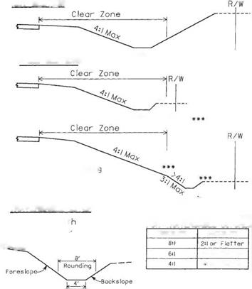
Clear zone grading is the shaping of the roadside using 4:1 or flatter foreslopes and traversable ditches within the clear zone area. Foreslopes of 3:1 may be used but are not measured as part of the clear zone distance. Clear zone grading is recommended

(A)

Grading and Side Slopes

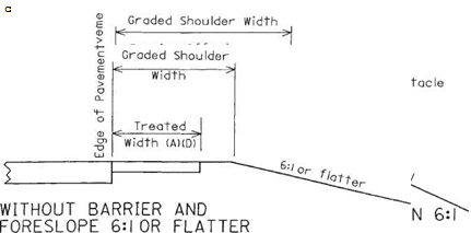
Treated width includes that portion of the shoulder improved with stabilized aggregate or better.

(B) Minimum barrier clearance.

(C) 3’on interstate, other freeways and expressways.

(D) Treated shoulder width may equal graded shoulder width in some cases.

FIGURE 2.13 Cross sections of shoulders showing graded and treated shoulder widths. Conversions: 2 ft = 0.61 m, 3 ft = 0.91 m. (From Location and Design Manual, Vol. 1, Roadway Design, Ohio Department of Transportation, with permission) for undivided rural facilities where the design speed exceeds 50 mi/h (80 km/h), the design hourly volume is 100 or greater, and at least one of the following conditions exists:

• The wider cross section is consistent with present or future planning for the facility.

• The project is new construction or major reconstruction involving significant length.

• The wider cross section can be provided at little or no additional cost.

Grading and Side Slopes

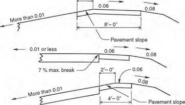
FIGURE 2.14 Recommended cross slopes and grade breaks for paved shoulders. Conversion: 1 ft = 0.305 m. (From Location and Design Manual, Vol. 1, Roadway Design, Ohio Department of Transportation, with permission)

Figure 2.19 shows examples of clear zone grading and traversable ditches.

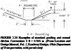
Standard grading is the shaping of the roadside using 3:1 or flatter foreslopes and normal ditches. Standard grading is used on undivided facilities where the conditions for the use of safety grading or clear zone grading do not exist. The designer should ensure that any obstacles within the clear zone receive proper protection. Figure 2.20 shows examples of standard grading and normal ditches.

Grading and Side Slopes

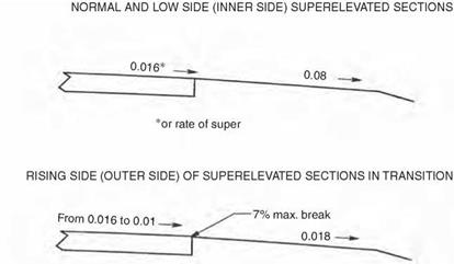
HIGH SIDE OF SUPERELEVATED SECTIONS

Grading and Side Slopes

2′- 6"

Grading and Side Slopes

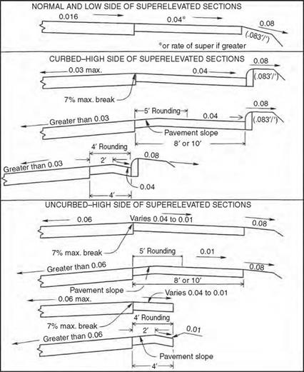
FIGURE 2.15 Recommended cross slopes and grade breaks for bituminous surface treated or stabilized aggregate shoulders. Conversion: 1 ft = 0.305 m. (From Location and Design Manual, Vol. 1, Roadway Design, Ohio Department of Transportation, with permission)

Barrier grading is the shaping of the roadside when a barrier is required for slope protection. Normally, 2:1 foreslopes and normal ditch sections are used. Figure 2.20 includes an example of barrier grading.

Rounding of Slopes. Slopes should be rounded at the break points and at the intersection with the existing ground line to reduce the chance of a vehicle’s becoming airborne and to harmonize with the existing topography. Rounding at various locations is illustrated in Figs. 2.17 to 2.20.

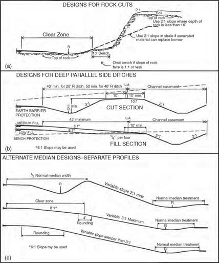
Special Median Grading. Figure 2.21c shows some examples of median grading when separate roadway profiles are used.

Grading and Side Slopes

HIGH SIDE OF SUPERELEVATED SECTIONS

Grading and Side Slopes

The break at the edge of the pavement shall not exceed 7%.

FIGURE 2.16 Recommended cross slopes and grade brakes for turf shoulders. Conversion: 1 ft = 0.305 m. (From Location and Design Manual, Vol. 1, Roadway Design, Ohio Department of Transportation, with permission)

Rock and Shale Slopes. In rock or shale cuts, the maximum rate of slope should be determined by a soils engineer. In deep rock or shale cuts where slopes are steeper than 1:1, a 10-ft-wide (3.05-m) bench should be provided between the top of the ditch back – slope and the toe of the rock face as illustrated in Fig. 2.21a. In shale cuts, the designer should not use backslopes steeper than 2:1 unless excessive waste would result. In any event, 2:1 slopes should be used for all shale cut sections less than 20 ft (7 m) in depth, and the bench should be omitted. In this discussion, depth of cut is measured from the top of shale or rock to the ditch flow line. Backslopes steeper than 2:1 should not be used in rock cuts until the depth exceeds 16 ft (5 m). In such cases the bench may be omitted.

Curbed Streets. Figure 2.22 shows typical slope treatments next to curbed streets.

Driveways and Crossroads. At driveways or crossroads, where the roadside ditch is within the clear zone distance and where clear zone grading can be obtained, the ditch and pipe should be located as shown on Fig. 2.23.

Подпись: -T2f.TYY , у-* tyj isrsrsrmL = о — •* CO V ◦ CO N Approximate guide for cut depth ” Grading and Side SlopesCUT SECTION

URBAN INTERSTATE, OTHER FREEWAYS AND EXPRESSWAYS

I • 8:1 I

9-6- oitch

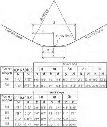
If backslope exceeds 3:1, use 40′ radius as shown above.

Подпись:SHALLOW CUT OR LOW FILL

•*

Recoverable Oitch

Slope transition between low fill design and medium fill design shall be such that the flowline of the roadside ditch does not turn toward the roadway.

Подпись: t 6:1 slope may be usedПодпись:Grading and Side Slopes

Grading and Side Slopes

K – Clear zone – sj

Ml]}

MEDIUM FILL

Application of these sections may vary to avoid frequent slope changes and to maintain reasonably straight ditches.

FIGURE 2.17 Cross sections showing safety grading for four different conditions. Conversion: 1 ft = 0.305 m. (From Location and Design Manual, Vol. 1, Roadway Design, Ohio Department of Transportation, with permission)

Ditches. When the depth or velocity of the design discharge accumulating in a roadside or median ditch exceeds the desirable maximum established for the various highway clas­sifications, a storm sewer will be required to intercept the flow and carry it to a satisfactory outlet. If right-of-way and earthwork considerations are favorable, a deep, parallel side ditch (see Fig. 2.21b) may be more practical and should be considered instead of a storm sewer. In some cases where large areas contribute flow to a highly erodible soil cut, an intercepting ditch may be considered near the top of the cut to intercept the flow from the

Grading and Side Slopes

FIGURE 2.18 Details of ditch rounding for safety grading. Conversions: 1 ft = 0.305 m, 1 in = 0.0254 m. (From Location and Design Manual, Vol. 1, Roadway Design, Ohio Department of Transportation, with permission)

outside and thereby relieve the roadside ditch. Constant-depth ditches (usually 18 in or 0.46 m deep) are desirable. Where used, the minimum pavement profile grades should be 0.24 to 0.48 percent. Where flatter pavement grades are necessary, separate ditch profiles are developed and the ditch flow line elevations shown on each cross section.

Parallel Channels. Where it is determined that a stream intercepted by the roadway improvement is to be relocated parallel to the roadway, the channel should be located beyond the limited access line (or highway easement line) in a separate channel ease­ment. This arrangement locates the channel beyond the right-of-way fence, if one is to be installed. Figure 2.21b shows a parallel channel section. This does not apply to con­ventional intercepting erosion control ditches located at the top of cut slopes in rolling terrain.

In areas of low fill and shallow cut, protection along a channel by a wide bench is usually provided. Fill slope should not exceed 6:1 when this design is used, and maxi­mum height from shoulder edge to bench should generally not exceed 10 ft (3.05 m). If it should become necessary to use slopes steeper than 6:1, guiderail may be necessary

Подпись: Traversable Ditch (See below)
Подпись: **FILL SECTIONS

Grading and Side SlopesCUT SECTION

**■*

Подпись: 4' RoundingTraversable Ditch
(See below)

**For fill heights over!6′ use barrier gradlnc

Normal Ditch

Подпись: Minimum Dept Cut: |.5', Fill: i.O ^toujder Grading and Side Slopes

TRAVERSABLE DITCH

FIGURE 2.19 Examples of clear zone grading and traversable ditches. Conversion: 1 ft = 0.305 m. (From Location and Design Manual, Vol. 1, Roadway Design, Ohio Department of Transportation, with permission)

and fill slopes as steep as 2:1 may be used. In cut sections 5 ft (1.52 m) or more in depth, earth barrier protection can be provided. This design probably affords greater protection where very deep channels are constructed and requires less excavation. Where the sections alternate between cut and fill and it is desired to use but a single design, earth barrier protection is less costly if waste excavation material is available. Likewise, bench protection is less costly if borrow is needed on the project as a whole.

Earth bench or earth barrier protection provided adjacent to parallel channels should not be breached for any reason other than to provide an opening for a natural or relocated stream that requires a drainage structure larger in rise than 42 in (1.07 m). Outlet pipes from median drains or side ditches should discharge directly into the par­allel channel.

Channels and toe-of-slope ditches, used in connection with steep fill slopes, are both removed from the normal roadside section by benches. The designer should establish control offsets to the center of each channel or ditch at appropriate points that govern alignment so the flow will follow the best and most direct course to the outlet. Bench width should be varied as necessary.

STANDARD GRADING

Подпись:

Подпись: 51 or I ess BARRIER GRADING Подпись: Over 5' Grading and Side Slopes
Grading and Side Slopes

FILL

Подпись: Slope all benches to drain ■ (3 to 5% recommended) & * Подпись:Подпись:

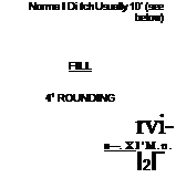
Подпись: Norma I Di tch Usually 10' (see below) FILL 41 ROUNDING rvi- ■—. X I'M.n. І2Г
Подпись: NORMAL DITCH SECTIONS CUT

Slope may be flatter than l^^b’V Exceeds 16 if excess material and right – 0r> » ^ of-way are available at little cost. ‘•*/

Interchange Grading. Interchange interiors should be contour-graded so that maximum safety is provided and the least amount of guiderail is required. Figures 2.24 and 2.25 show examples. The generous use of flat slopes (6:1 or flatter) will also be easier for main­tenance crews to work with. Sight distance is critical for passenger vehicles on ramps as they approach entrance or merge areas. Therefore, sight distance should be unobstructed by landscaping, earth mounds, or other barriers on the merging side of the vehicle.

Crossroads. At a road crossing within an interchange area, bridge spill-through slopes should be 2:1, unless otherwise required by structure design. They should be flattened to 3:1 or flatter in each corner cone and maintained at 3:1 or flatter if within the interior of an interchange. Elsewhere in interchange interiors, fill slopes should not exceed 3:1.

Ramps. Roadside design for ramps should be based on Fig. 2.17 or 2.18, depending on the mainline grading concept.

Grading and Side Slopes

FIGURE 2.21 Examples of special designs for grading. (a) Designs for rock cuts. (b) Designs for deep, parallel side ditches. (c) Alternate median designs. Conversion: 1 ft = 0.305 m. (From Location and Design Manual, Vol. 1, Roadway Design, Ohio Department of Transportation, with permission)

Gore Area. Gore areas of trumpets, diamonds, and exteriors of loops adjacent to the exit point should be graded to obtain slopes of 6:1 or flatter, which will not endanger a vehicle unable to negotiate the curvature because of excessive speed.

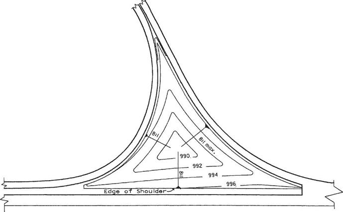
Trumpet Interiors. Interior areas of trumpets (Fig. 2.24) should be graded to slopes not in excess of 8:1, sloping downward from each side of the triangle to a single, rounded low point. Roadside ditches should not be used. Exteriors should be graded in accordance with mainline or ramp standards.

Grading and Side Slopes

To be used on clear zone grading projects where the roadside ditch flowline is located within the clear zone distance

FIGURE 2.23 Slopes and ditches at driveway and crossroad in cut or low fill for use on clear zone grading projects where ditch is within clear zone distance. (From Location and Design Manual, Vol. 1, Roadway Design, Ohio Department of Transportation, with permission)

Подпись: 135Grading and Side Slopes

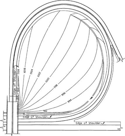
Loop Interiors. In cut, the interior of a loop should be graded to form a normal ditch section adjacent to the lower part of the loop, and the backslope should be extended to intersect the opposite shoulder of the upper part of the loop. This applies unless the character and the amount of material or the adjacent earthwork balances indicate that the cost would be prohibitive. Roadside cleanup and landscaping should be provided in undisturbed areas of loop interiors. If channels are permitted to cross the loop interior, slopes should not be steeper than 4:1. Figure 2.25 shows an example.

Diamond Interiors. If the location of the ramp intersection at the crossroad is relatively near the main facility, a continuous slope between the upper roadway shoulder and the lower roadway ditch will provide the best and most pleasing design. If the ramp

Grading and Side Slopes

FIGURE 2.25 Contour grading of loop interior in cut section at interchange with contour elevations shown in feet. Conversion: 1 ft = 0.305 m. (From Location and Design Manual, Vol. 1, Roadway Design, Ohio Department of Transportation, with permission)

intersection at the crossroad is located a considerable distance from the main facility, then both ramp and mainline roadsides should have independent designs, until the slopes merge near the gore.

If the quadrant is entirely, or nearly so, in cut, the combination of a 3:1 backslope at the low roadway ditch and a gentle slope down from the high roadway shoulder will provide the best design in the wide portion of the quadrant. Approaching the gore, the slopes should transition to continuous 4:1 and 6:1 or flatter slopes. Quadrants located entirely in fill areas should have independently designed roadways for ramp, mainline, and crossroad. Each should be provided with normal slopes not greater than 3:1, with the otherwise ungraded areas sloped to drain without using ditches. If the quadrant is located part in cut and part in fill, the best design features a gentle fill slope at the upper roadway and a gentle backslope at the lower roadway, joined to a bench at the existing ground level that is sloped to drain. The combination of a long diamond ramp having gentle alignment with a loop ramp in the same interchange quadrant is not to be treated as a trumpet. Each ramp should be designed independently of the other in accordance with the suggested details set forth above.

2.3.1 Bridge Criteria

Although bridge engineering is discussed in Chap. 4, information on pertinent physical dimensions is presented here. Lateral clearance at underpasses and vertical clearance over roadways, as used in Ohio, are given in Table 2.25 for new and reconstructed bridges. The table notes provide a good insight into when variations from the standards are allowed.

Roadway Criteria

Lane Widths and Transitions. When considering the physical characteristics of cross sections, the values selected will depend on location (rural or urban), speed, traffic volumes, functional classification, and, in urban areas, the type of adjacent development. Tables 2.21, 2.22, and 2.23 provide values currently used in Ohio. Lane width is dependent on design speed, especially in rural areas. Widths may be as narrow as 9 ft (2.74 m) for a local, low-volume road. In urban areas, lane widths can be as narrow as 10 ft (3.05 m), if the road is primarily a residential street. The maximum lane width is generally accepted to be 12 ft (3.66 m) in all locales.

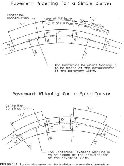
In some cases it may be necessary to widen the pavement on sharp curves to accommodate off-tracking of larger vehicles. Table 2.24 provides a chart of recom­mended pavement widening based on degree of curvature and design speed. These values are based on a WB-50 design vehicle. The widened portion of the pavement is normally placed on the inside of the curve. Where curves are introduced with spiral transitions, the widening occurs over the length of the spiral. On alignments without spirals, the widening is developed over the same distance that the superelevation tran­sition occurs. The centerline pavement marking and the center joint (if applicable) should be placed equidistant from the pavement edges. See Fig. 2.12 for illustrations of curve widening.

Whenever the driver’s lane is being shifted—for example, when lanes are being added or eliminated—the shifting rate should be controlled using the following equations:

L = WS for design speeds over 40 mi/h (2.5)

S 2

L = W for design speeds up to 40 mi/h (2.6)

where L = approach taper length, ft W = offset width, ft S = design speed, mi/h

Where lanes are being added but the driver is not being “forced” to follow the actual transition (such as in adding right turn lanes), the transition can occur in 50 ft (15 m) on most roadways or 100 ft (30 m) on freeway designs.

Pavement Cross Slopes. Roadways on tangent or relatively straight alignments where no superelevation is required are normally crowned (peaked) in the middle. Cross slopes are usually in the range of 0.015 to 0.020 ft/ft (m/m). Urban areas with curbed pavements are more likely to have a slope near the upper limit, while rural roadways tend to have a little flatter cross slope. The following guidelines are applica­ble to the location of the crown point:

• Crowns should be located at or near lane lines.

• For pavements with three or four lanes, no more than two should slope in the same direction.

• Undivided pavement sections should be crowned in the middle when the number of lanes is even, and at the edge of the center lane when the number is odd.

• Narrow raised median sections should be crowned in the middle, so that the majority of the pavement will drain to the outside.

TABLE 2.21 Guide for Selecting Lane Width for Rural Areas(A)

Minimum lane widths, ft,[2] for design speed, mi/h

Functional

classification

Design year ADT

20

25

30

35

40

45

50

55

60

65

70 or >

Interstate, other

ALL

12

12

12

12

12

freeways and expressways Arterial

> 4000

12

12

12

12

12

12

12

2001-4000

12

12

12

12

12

12

12

1001-2000

11

11

12

12

12

12

12

400-1000

11

11

12

12

12

12

12

< 400

11

11

12

12

12

12

12

Collector

> 4000

12

12

12

12

12

12

(C)

12

(C)

12

12

2001-4000

12

12

12

12

12

12

12

12

12

1001-2000

11

11

11

11

11

11

11

12

12

400-1000

10

10

10

11

11

11

11

11

11

< 400

10

10

10

10

10

10

10

11

11

Local

> 4000

12

12

12

12

12

12

12

12

12

2001-4000

12

12

12

12

12

12

12

12

12

1001-2000

(D)

10

(D)

11

(D)

11

(D)

11

(D)

11

(D)

11

11

12

12

400-1000

10

10

10

10

11

11

11

11

11

< 400

9

9

9

9

9

10

10

11

11

Conversions: 1 mi/h = 1.609 km/h, 1 ft = 0.305 m. Notes:

(A) There may be some rural locations that are urban in character. An example would be a village where adjacent development and other conditions resemble an urban area. In such cases, urban design criteria may be used.

(B) The number of lanes should be determined by a capacity analysis.

(C) May be 11 ft on nonfederal projects if design year ADT includes less than 25 (B) and (C) truck units.

(D) An 11-ft lane width may be retained on reconstructed highways if the alignment and safety records are satisfactory.

Source: Location and Design Manual, Vol. 1, Roadway Design, Ohio Department of Transportation, with

permission.

Shoulders. A shoulder is the area adjacent to the roadway that (1) when properly designed, can provide lateral support to the pavement, (2) is available to the motorist in emergency situations, and (3) can be used to maintain traffic during construction. Graded shoulder width is the width of the shoulder measured from the edge of the pavement to the intersection of the shoulder slope and the foreslope. Treated shoulder width is that portion of the graded shoulder that has been improved to at least stabilized aggregate or better. Figure 2.13 illustrates these definitions.

Four basic types of shoulders are used: (1) paved, (2) bituminous surface treated,

(3) stabilized aggregate, and (4) turf. Paved shoulders may be rigid (concrete) or flexible (asphalt). Turf shoulders are usually used on low-volume, uncurbed, local roads. Tables 2.22 and 2.23 provide recommended shoulder widths and types based on functional classification and traffic volumes or locale.

TABLE 2.22 Guide for Selecting Shoulders for Rural Areas’*1


Graded width, ft Rounding, ft (B)


Functional

Design year ADT

With barrier or foreslope steeper than 6:1

Without barrier 6:1 or flatter

Treated

for design speed, mi/h

Guardrail offset, ft (from traveled way) (D)

classification

foreslope

width, ft

Type(C)

> 50

< 50

Interstate, Other Freeways & Expressways

All

17′ Rt.

9′ Med. (E)

12′ Rt.

4′ Med. (F)

12′ Rt. (G) 4′ Med. (F)

Paved

10′

(H)

Arterial (K)

>4000

14′

10′

10′

PVD (I)

8′

4′

12′

2001U000

12′

8′

8′

PVD (I)

8′

4′

10′

1001-2000

10′

8′

6′

BIT. SRF. TRT.(L)

8′

4′

8′

400-1000

10′

8′

6′

BIT. SRF. TRT.(L)

4′

4′

8′

<400

8′

8′

4′

STBL. AGG.

4′

4′

6′

Collector (K)

>4000

12′

8′

8′(M)

BIT. SRF. TRT. (L)

8′

4′

10′(N)

2001-4000

10′

8′

4′

BIT. SRF. TRT. (L)

8′

4′

8′(N)

1001-2000

8′

640)

4′

STBL. AGG.

8′

4′

6′(N)

400-1000

6′

4′

4′

STBL. AGG.

4′

4′

4′

<400

6′

(P)

(P)

STBL. AGG

4′

4′

4′

Local

>4000

12′

8′ (Q)

8′(M)

BIT. SRF. TRT.(L)

8′

4′

10′(N)

2001-4000

10′

8′ (Q)

4′

BIT. SRF. TRT. (L)

8′

4′

8′(N)

1001-2000

8′

640)

4′

STBL. AGG

8′

4′

6′(N)

400-1000

6′

4′

4′

STBL. AGG.

4′

4′

4′

<400

6′

(P)

(P)

STBL. AGG.

4′

4′

4′


Подпись: 120

(E) If 6 or more lanes, use 17 ft. If the truck traffic is less than 250 DDHV use 15 ft.

(F) If 6 or more lanes, use 12 ft. If truck traffic is less than 250 DDHV, 10 ft treated width may be used.

(G) Use 10 ft if truck traffic is less than 250 DDHV. If 10 ft treated width is used, graded width may be reduced by 2 ft.

(H) Guardrail offset is treated width plus 2 ft.

(I) A fully paved shoulder is preferred, but may not be economically feasible. Therefore, a minimum 2 ft of the treated shoulder should be paved. The remainder of the treated shoulder may be either stabilized aggregate or bituminous surface-treat­ed material according to the criteria stipulated in Notes (K) and (L).

(J) Use bituminous surface treated if design year ADT includes between 250 and 1000 (B) and (C) truck units.

(K) The median shoulder width criteria for interstates, other freeways and expressways shall apply to the medians of divided arterials and divided collectors.

(L) Stabilized aggregate may be used on state-maintained roads if the design year ADT includes less than 250 (B) and (C) truck units. Paved shoulders are recommended if the design year ADT includes over 1000 (B) and (C) truck units.

(M) Use 6 ft if design year ADT includes less than 501 (B) and (C) truck units. If 6 ft treated width is used, graded width may be reduced to 10 ft and minimum barrier offset will be 8 ft.

(N) Whenever a design exception is approved for graded shoulder width, the guardrail offset may be reduced but shall not be less than 4 ft.

(O) A 6-ft turf shoulder may be used with a 4:1 or flatter foreslope.

(P) See AASHTO’S Guidelines for Geometric Design for Very Low-Volume Local Roads for values.

(Q) An 8-ft graded shoulder may be used with a 4:1 or flatter foreslope.

Source: Location and Design Manual, Vol. 1, Roadway Design, Ohio Department of Transportation, with permission.

TABLE 2.23 Guide for Selecting Lane Width and Shoulders for Urban Areasa

Functional

classification

Locale

Lane width, ft Minimum Preferred

Minimum curbed shoulder width,’b ft

Without With parking lane parking lanec

Interstates, other freeways, and expressways

All

12

12

12 right paved,

4 median paved de

Arterial streets

50 mi/h or more

12

12

10 each side paved

Less than 50 mi/h

12h

12

1-2 paved

10-12 paved

Collector streets

Commercial or industrial

11

12

1-2 paved

9-10 paved

Residential

11

12

1-2 paved

7-10 paved

Local streets

Commercial or industrial

11

12

1-2 paved

9 paved

Residential

10′

11

1-2 paved

7 paved

Conversions: 1 mi/h = 1.609 km/h, 1 ft = 0.305 m.

aUse rural criteria (Tables 2.21 and 2.22) for uncurbed shoulders. Rural functional classification should be determined after checking the urban route extension into a rural area.

‘See Sections 305.3.2 and 305.3.3 for use of curbs and notes on curb/guardrail relationships.

cUse minimum lane width if, in the foreseeable future, the parking lane will be used for through traffic during peak hours or continuously.

dUse 10 ft median shoulder on facilities with 6 or more lanes. Use 12 ft median shoulder on facilities with 6 or more lanes and when truck traffic exceeds 250 DDHV.

eMay be reduced to 10 ft if the truck traffic is less than 250 DDHV.

fMay be reduced to 8 ft if DHV is less than 250.

gThe median shoulder width for divided arterials shall follow the median criteria for Interstates, other Freeways and Expressways.

hLane width may be reduced to 11 ft where right-of-way is limited and current truck ADT is less than 250; however, on all Federal Aid Primary (FAP) roadways at least one 12-ft lane in each direction is required. FAP listings may be obtained from Office of Technical Services’s Roadway Inventory reports.

‘Lane width may be 9 ft where right-of-way is limited and current ADT is less than 250.

Source: Location and Design Manual, Vol. 1, Roadway Design, Ohio Department of Transportation, with permission.

Whenever practical, shoulders should be designed to be wide enough and strong enough to accommodate temporary traffic, especially on high-volume roadways. Figures 2.14, 2.15, and 2.16 provide information on recommended cross slopes [ft/ft (m/m)] and allowable grade breaks depending on the type of shoulder chosen.

CROSS-SECTION DESIGN

This article provides information to assist the designer in determining lane widths, pavement cross slopes, shoulder widths, interchange cross-section elements, medians, curbs, pedestrian facilities, and grading and side slopes. The number of lanes for a given roadway facility is best determined using principles and procedures contained in the “Highway Capacity Manual” (Ref. 10). This manual analyzes roadways to determine an appropriate “level of service,” by which a letter value (A through F) is assigned depending on the volume of traffic and other geometric features. Table 2.20 provides a design guide for level of service for various facilities by functional classification and terrain or locale. The table includes a brief description of the characteristics of each level of service.

TABLE 2.20 Guide for Selecting Design Service Level As Determined by Function and Terrain or Locale

Minimum level of service for area and terrain or locale

Functional

classification

Level

Rolling

Hilly

Urban and suburban

Interstate, other

B

B

C

C

freeways, and

expressways

Arterial

B

B

C

C

Collector

C

C

D

D

Local

D

D

D

D

A: Free flow, with low volumes and high speeds.

B: Stable flow, speeds beginning to be restricted by traffic conditions.

C: In stable flow zone, but most drivers are restricted in freedom to select own speed.

D: Approaching unstable flow; drivers have little freedom to maneuver. E: Unstable flow; short stoppages may occur.

F: Forced or breakdown flow.

Source: Location and Design Manual, Vol. 1, Roadway Design, Ohio

Department of Transportation, with permission.

Coordination of Horizontal and Vertical Alignments

When designing new roadway projects, the following items should be considered to

coordinate the horizontal and vertical alignments:

• Curvature and tangent sections should be properly balanced. Normally, horizontal curves will be longer than vertical curves.

• It is generally more pleasing to the driver when vertical curvature can be superimposed on horizontal curvature. In other words, the PIs (points of intersection) of both the vertical and horizontal curves should be near the same station or location.

• Sharp horizontal curves should not be introduced at or near the top of a pro­nounced crest vertical curve or at or near the low point of a pronounced sag vertical

curve.

TABLE 2.19 Stopping Sight Distance for Sag Vertical Curves at Design Speeds from 20 to 70 mi/h (32 to 113 km/h)

Подпись: Design speed, mi/h Design SSD, ft Design K, ft/% 20 115 17 21 120 18 22 130 20 23 140 22 24 145 24 25 155 26 26 165 28 27 170 29 28 180 32 29 190 34 30 200 37 31 210 39 32 220 42 33 230 44 34 240 47 35 250 49 36 260 52 37 270 55 38 280 57 39 290 60 40 305 64 41 315 66 42 325 69 43 340 73 44 350 76 45 360 79 Подпись: Design speed, mi/h Design SSD, ft Design K, ft/% 46 375 83 47 385 85 48 400 89 49 415 93 50 425 96 51 440 100 52 455 104 53 465 107 54 480 111 55 495 115 56 510 119 57 525 123 58 540 128 59 555 132 60 570 136 61 585 140 62 600 144 63 615 148 64 630 153 65 645 157 66 665 162 67 680 167 68 695 171 69 715 176 70 730 181

Подпись: For S < L: S

Подпись: Using S = stopping sight distance, ft L = length of sag vertical curve, ft A = algebraic difference in grades, %, absolute value K = rate of vertical curvature, ft per % change • For a given design speed and A value, the calculated length L = KA • To determine S with a given L and A, use the following:
Подпись: 3.5L + V12.25L2 + 160052 2A
Подпись: For S > L: S = (AL + 400)/(2A - 3.5)
Подпись: Conversions: 1 mi/h = 1.609 km/h, 1 ft = 0.305 m. Note: When the algebraic difference A is 1.75 percent or less, SSD is not restricted by the vertical curve. Source: Location and Design Manual, Vol. 1, Roadway Design, Ohio Department of Transportation, with permission.

Height of headlight = 2.00 ft Upward light beam divergence = 1°00′

• On two-lane roadways, long tangent sections (horizontal and vertical) are desirable to provide adequate passing sections.

• Horizontal and vertical curves should be as flat as possible at intersections.

• On divided highways, the use of variable median widths and separate horizontal and vertical alignments should be considered.

• In urban areas, horizontal and vertical alignments should be designed to minimize nuisance factors. These might include directional adjustment to increase buffer zones and depressed roadways to decrease noise.

• Horizontal and vertical alignments may often be adjusted to enhance views of scenic areas.

Vertical Alignment

The design of the vertical alignment of a roadway also has a direct effect on the safety and comfort of the driver. Steep grades can slow down large, heavy vehicles in the traffic stream in the uphill direction and can adversely affect stopping ability in the downhill direction. Grades that are flat or nearly flat over extended distances will slow down the rate at which the pavement surface drains. Vertical curves provide a smooth change between two tangent grades, but must be designed to provide adequate stopping sight distance.

Tangent Grades. The maximum percent grade for a given roadway is determined by its functional classification, surrounding terrain, and design speed. Table 2.16 shows how the maximum grade can vary under different circumstances. Note that relatively flat grade limits are recommended for higher functional class roadways and at higher design speeds, whereas steeper grade limits are permitted for local roads and at lower design speeds.

Concerning minimum grades, flat and level grades may be used on uncurbed roadways without objection, as long as the pavement is adequately crowned to drain the surface laterally. The preferred minimum grade for curbed pavements is 0.5 percent, but a grade of 0.3 percent may be used where there is a high-type pavement accurately crowned and supported on firm subgrade.

Critical Length of Grade. Freedom and safety of movement on two-lane highways are adversely affected by heavily loaded vehicles operating on upgrades of sufficient lengths to result in speeds that could impede following vehicles. The term critical length of grade is defined as the length of a particular upgrade which reduces the operating speed of a truck with a weight-to-horsepower ratio of 200 lb/hp (0.122 kg/W) to 10 mi/h (1.6 km/h) below the operating speed of the remaining traffic. Figure 2.11 provides the amount of speed reduction for these trucks given a range of percent upgrades and length of grades. The entering speed is assumed to be 70 mi/h (113 km/h). The curve representing a 10-mi/h (1.6-km/h) reduction is the design guideline to be used in determining the critical length of grade.

Design speed, mi/h

TABLE 2.16 Maximum Grades as Determined by Function, Terrain, and Speed, %

Functional

classification

Terrain

25

30

35

40

45

50

55

60

65

70

75—

Urban:

Interstate,* other

freeways, and

expressways

Level

4

4

3

3

3

3

Rolling

5

5

4

4

4

4

Hilly

6

6

6

5

5

Arterial street^

Level

8

7

7

6

6

5

5

Rolling

9

8

8

7

7

6

6

Hilly

11

10

10

9

9

8

8

Collector streets^

Level

9

9

9

9

8

7

7

6

Rolling

12

11

10

10

9

8

8

7

Hilly

13

12

12

12

11

10

10

9

Local streets^

Level

7

7

7

7

7

6

6

5

Rolling

11

10

10

10

9

8

7

6

Hilly

15

14

13

13

12

10

10

Rural:

Interstate,* other

freeways, and

expressways

Level

4

4

3

3

3

3

Rolling

5

5

4

4

4

4

Hilly

6

6

6

5

5

Arterials^

Level

5

5

4

4

3

3

3

3

Rolling

6

6

5

5

4

4

4

4

Hilly

8

7

7

6

6

5

5

5

Collectors^

Level

7

7

7

7

7

6

6

5

Rolling

10

9

9

8

8

7

7

6

Hilly

11

10

10

10

10

9

9

8

Local roads’^

Level

7

7

7

7

7

6

6

5

Rolling

11

10

10

10

9

8

7

6

Hilly

15

14

13

13

12

10

10

Conversions: 1 mi/h = 1.609 km/h, 1 ft = 0.305 m.

*Grades 1% steeper may be used for extreme cases where development in urban areas precludes the use of flatter grades. Grades 1% steeper may also be used for one-way down-grades except in hilly terrain.

^Grades 1% steeper may be used for short lengths (less than 500 ft) and on one-way down-grades. For rural highways with current ADT less than 400, grades may be 2% steeper.

Source: Location and Design Manual, Vol. 1, Roadway Design. Ohio Department of Transportation, with

permission.

If after an investigation of the project grade line, it is found that the critical length of grade must be exceeded, an analysis of the effect of the long grades on the level of service of the roadway should be made. Where speeds resulting from trucks climbing up long grades are calculated to fall within the range of service level D or lower, consideration should be given to constructing added uphill lanes on critical lengths of grade. Refer to the “Highway Capacity Manual” (Ref. 10) for methodology in determining level of service. Where the length of added lanes needed to preserve the recommended level of service on sections with long grades exceeds 10 percent of the total distance between major termini, consideration should be given to the ultimate construction of a divided multilane facility.

Vertical Alignment

FIGURE 2.11 Critical lengths of grade based on typical heavy truck of 200 lb/hp (0.122 kg/W) at entering speed of 70 mi/h (113 km/h). Notes: (1) This graph can also be used to compute the critical length of grade for grade combinations. For example, find the critical length of grade for a 4 percent upgrade preceded by 2000 ft (610 m) of 2 percent upgrade and a tolerable speed reduction of 15 mi/h (24 km/h). From the graph, 2000 ft (610 m) of 2 percent upgrade results in a speed reduction of 7 mi/h (11 km/h). Subtracting 7 mi/h (11.2 km/h) from the tolerable speed reduction of 15 mi/h (24 km/h) gives the remaining tolerable speed reduction of 8 mi/h (12.8 km/h). The graph shows that the remaining tolerable speed reduction would occur on 1000 ft (305 m) of the 4 percent upgrade. (2) The critical length of grade is the length of tangent grade. When a vertical curve is part of the critical length of grade, an approximate equivalent tangent grade should be used. Where A < 3 percent, the vertical tangent lengths can be used (VPI to VPI). Where A > 3 percent, about V4 of the vertical curve length should be used as part of the tangent grade. Conversions: 1 mi/h = 1.609 km/h, 1 ft = 0.305 m. (From Location and Design Manual, Vol. 1, Roadway Design, Ohio Department of Transportation, with permission)

Vertical Curves. A vertical curve is used to provide a smooth transition between vertical tangents of different grades. It is a parabolic curve and is usually centered on the intersection point of the vertical tangents. One of the principles of parabolic curves is that the rate of change of slope is a constant throughout the curve. For a vertical curve, this rate is equal to the length of the curve divided by the algebraic difference of the grades. This value is called the K value and represents the distance required for the vertical tangent to change by 1 percent. The K value is useful in design to determine the minimum length of vertical curve necessary to provide minimum stopping sight distance given two vertical grades.

Allowable Grade Breaks. There are situations where it is not necessary to provide a vertical curve at the intersection of two vertical grades because the difference in grades is not large enough to provide any discomfort to the driver. The difference

TABLE 2.17 Maximum Change in Vertical Alignment Not Requiring a Vertical Curve

Design speed, mi/h

Design speed, km/h

Maximum grade change, %*

25

40

1.85

30

48

1.30

35

56

0.95

40

64

0.75

45

72

0.55

50

80

0.45

55

88

0.40

60

96

0.30

65

105

0.30

70

113

0.25

Based on the following equation:

. = 46.5L = 1162.5

A = V2 = V2

where A = maximum grade change, %

L = length of vertical curve, ft; assume 25 V = design speed, mi/h

Note: The recommended minimum distance between consecutive deflections is 100 ft (30 m) where design speed > 40 mi/h (64 km/h) and 50 ft (15 m) where design speed < 40 mi/h.

*Rounded to nearest 0.05%.

Source: Location and Design Manual, Vol. 1, Roadway

Design, Ohio Department of Transportation, with permission.

varies with the design speed of the roadway. At 25 mi/h (40 km/h), a grade break of 1.85 percent without a curve may be permitted, while at 55 mi/h (88 km/h) the allow­able difference is only 0.40 percent. Table 2.17 lists the maximum grade break permitted without using a vertical curve for various design speeds. The equation used to develop the distances is indicated as well as a recommended minimum distance between con­secutive grade breaks. Where consecutive grade breaks occur within 100 ft (30 m) for design speeds over 40 mi/h (64 km/h), or within 50 ft (15 m) for design speeds at 40 mi/h (64 km/h) and under, this indicates that a vertical curve may be a better solution than not providing one.

Crest Vertical Curves. The major design consideration for crest vertical curves is the provision of ample stopping sight distance for the design speed. Calculations of available stopping sight distance are based on the driver’s eye 3.5 ft (1.07 m) above the roadway surface with the ability to see an object 2 ft (0.61 m) high on the roadway ahead over the top of the pavement. Table 2.18 lists the calculated design stopping sight distance values and the corresponding K values for design speeds from 20 to 70 mi/h (32 to 113 km/h). The values shown are based on the assumption that the curve is longer than the sight distance. In those cases where the sight distance exceeds the vertical curve length, a different equation is used to calculate the stopping sight distance pro­vided. The equations are shown in the table.

Another consideration in designing crest vertical curves is passing sight distance, especially when dealing with two-lane roadways. This has already been discussed

Height of eye, 3.50 ft; height of object, 2.00 ft

TABLE 2.18 Stopping Sight Distance (SSD) for Crest Vertical Curves at Design Speeds from 20 to 70 mi/h (32 to 113 km/h)

Design speed, mi/h

Design SSD, ft

Design K, ft/%

Design speed, mi/h

Design SSD, ft

Design K, ft/%

20

115

7

46

375

66

21

120

7

47

385

69

22

130

8

48

400

75

23

140

10

49

415

80

24

145

10

50

425

84

25

155

12

51

440

90

26

165

13

52

455

96

27

170

14

53

465

101

28

180

15

54

480

107

29

190

17

55

495

114

30

200

19

56

510

121

31

210

21

57

525

128

32

220

23

58

540

136

33

230

25

59

555

143

34

240

27

60

570

151

35

250

29

61

585

159

36

260

32

62

600

167

37

270

34

63

615

176

38

280

37

64

630

184

39

290

39

65

645

193

40

305

44

66

665

205

41

315

46

67

680

215

42

325

49

68

695

224

43

340

54

69

715

237

44

350

57

70

730

247

45

360

61

Using S = stopping sight distance, ft

L = length of crest vertical curve, ft A = algebraic difference in grades, %, absolute value K = rate of vertical curvature, ft per % change

• For a given design speed and A value, the calculated length L = KA.

• To determine S with a given L and A, use the following:

For S < L: S = 46.45VK where K = L/A

For S > L: S = 1079/A + L/2

Conversions: 1 mi/h = 1.609 km/h, 1 ft = 0.305 m.

Note: For design criteria pertaining to collectors and local roads wih ADT less than 400, please refer to the AASHTO publication, Guidelines for Geometric Design of Very Low-Volume Local Roads (ADT < 400).

Source: Location and Design Manual, Vol. 1, Roadway Design, Ohio

Department of Transportation, with permission.

under “Passing Sight Distance” earlier in this chapter. Also, in addition to being designed for safe stopping sight distance, crest vertical curves should be designed for comfortable operation and a pleasing appearance whenever possible. To accomplish this, the length of a crest curve in feet should be, as a minimum, 3 times the design speed in miles per hour.

Sag Vertical Curves. The main factor affecting the design of a sag vertical curve is head­light sight distance. When a vehicle traverses an unlighted sag vertical curve at night, the portion of highway lighted ahead is dependent on the position of the headlights and the direction of the light beam. For design purposes, the length of roadway lighted ahead is assumed to be the available stopping sight distance for the curve. In calculating the distances for a given set of grades and a length of curve, the height of the head­light is assumed to be 2 ft (0.61 m) and the upward divergence of the light beam is considered to be 1°. Table 2.19 lists the calculated design stopping sight distance values and the corresponding K values for design speeds from 20 to 70 mi/h (32 to 113 km/h). As was the case with crest curves, the values shown are based on the assumption that the curve is longer than the sight distance. In those cases where the sight distance exceeds the vertical curve length, a different equation is used to calculate the actual stopping sight distance provided as indicated in the table.

Note for sag curves, when the algebraic difference of grades is 1.75 percent or less, stopping sight distance is not restricted by the curve. In these cases, the equations in Table 2.19 will not provide meaningful answers. Minimum lengths of sag vertical curves are necessary to provide a pleasing general appearance of the highway. To accomplish this, the minimum length of a sag curve in feet should be equal to 3 times the design speed in miles per hour.

Vertical Alignment Considerations. The following items should be considered when establishing new vertical alignment:

• The profile should be smooth with gradual changes consistent with the type of facility and the character of the surrounding terrain.

• A “roller-coaster” or “hidden dip” profile should be avoided.

• Undulating grade lines involving substantial lengths of steeper grades should be appraised for their effect on traffic operation, since they may encourage excessive truck speeds.

• Broken-back grade lines (two vertical curves—a pair of either crest curves or sag curves—separated by a short tangent grade) should generally be avoided.

• Special attention should be given to drainage on curbed roadways where vertical curves have a K value of 167 or greater, since these areas are very flat.

• It is preferable to avoid long, sustained grades by breaking them into shorter intervals with steeper grades at the bottom.