Category HIGHWAY ENGINEERING HANDBOOK

THE COST OF CONGESTION

Congestion, when applied to traffic, refers to that condition which occurs when drivers experience a noticeable delay in completing a trip because of inability to maneuver through the traffic stream. This condition is characterized by slow travel speeds, increased travel times, increased accident frequencies, erratic stop-and-go driving, increased vehicle operating costs, and other undesirable circumstances leading to driver dissatisfaction (Ref. 4).

Congestion on urban freeways is of two types—recurring and nonrecurring. Congestion that occurs regularly at particular locations during certain time periods is said to be recurring. On the other hand, congestion that occurs as a result of irregular events, such as accidents, disabled vehicles, or other similar happenings, is said to be nonrecurring. Both can cause driver dissatisfaction, but drivers usually expect the recurring congestion and make adjustments in their travel plans to accommodate it. The most common example of recurring congestion is the morning and afternoon “rush hour” periods, when traffic demands can exceed the capacity of the freeway.

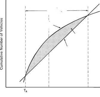
Figure 2.60 shows a graph illustrating what happens when demand exceeds capacity. The straight line represents the capacity of a section of freeway at a particular time (i. e., the number of vehicles getting past the point under prevailing roadway conditions). As long as traffic demand, or the number of vehicles arriving at that point (shown by the curved cumulative demand line), is less than or equal to the capacity of that section of the freeway, there is little congestion. However, once the arrival rate begins to exceed the capacity at time Ta, a bottleneck is formed and vehicles begin to accumulate upstream until time Tb, when the demand once again falls below the capacity. Congested conditions continue until time Tc, when the accumulated traffic at the bottleneck dissipates. The area between the capacity and demand curves during congested conditions is the delay result­ing from the congestion (Ref. 4).

THE COST OF CONGESTIONDuration of

Congestion

Cumulative

Demand

Delay

Capacity

Ть Tc

Time

FIGURE 2.60 Illustration of relationships among demand, capacity, and congestion. (From Traffic Engineering Handbook, Institute of Transportation Engineers, 1992)

The cost of congestion is the sum of individual costs of items that represent an increase over normal operating costs directly attributable to the congestion. Among these items are fuel and oil consumption, tire wear caused by the frequency and severity of speed changes, other maintenance items affected by the speed changes, and increased idling times. There are other costs that may not be readily apparent to the individual driver but are real costs affecting the general public, such as inefficient movement of commercial vehicles and the increased level of pollutant emissions.

Where congestion on freeways is of the recurring kind, the usual solutions to try and solve the problem are geometric in nature. The most logical solution in many cases is lane addition. In urban areas, congestion frequently occurs downstream from entrance ramps when the combination of traffic entering the freeway and the traffic already present exceeds the capacity of that segment. In other cases, the existing horizontal alignment may contain one or more “sharp” curves, which result in lower capacity. Ramp designs may have a detrimental effect on freeway capacity if their merge or diverge areas are too short, or if they are too closely spaced, creating weaving problems for traffic entering and exiting the freeway traffic stream. Other problems involving physical features include unconventional interchanges, inadequate shoulders, narrow medians, poor surface quality, and poor signing.

The next article discusses a new approach to the problem that takes advantage of evolving technology: intelligent vehicle highway systems.

Drive Profile Design

Drive profiles on uncurbed roadways should slope down and away from the pavement

edge at the same slope as the graded shoulder. Any vertical curve should be developed

Drive Profile Design

FIGURE 2.57 Designs for shopping center and industrial drives. Conversions: 1 ft = 0.305 m, 1 in = 25.4 mm. (From Location and Design Manual, Vol. 1, Roadway Design, Ohio Department of Transportation, with permission)

outside the normal graded shoulder width. Vertical curve lengths should be 10 to 20 ft (3.0 to 6.1 m), depending on the grade differential. Under normal circumstances, rural drive grades should not exceed 10 percent, with 8 percent the preferred maximum.

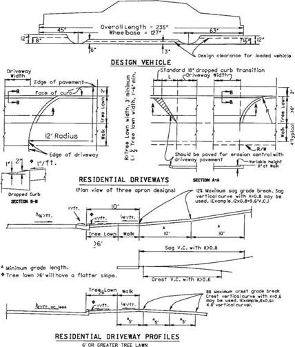
The drive profiles for curbed roadways were developed using the design vehicle described in Fig. 2.50. The profile criterion shown provides clearance for this vehicle when its springs are completely compressed. If conditions of a particular driveway do not meet the cross-section criteria listed below, a template of the design vehicle can be used to design the driveway profile.

For tree lawns 6 ft (1.8 m) or wider, the ramp grade from the gutter to the edge of the sidewalk should be 1 in/ft (8.3%) or less for normal cross-section design. Figure 2.50 shows this condition for the following cross-section conditions:

• Sidewalk and tree lawn slope of /4 in/ft (2.1%) and

• A 6-in (150-mm) curb height with pavement slope of %s or % in/ft (1.6 or 2.1%) or

• Type 2 curb and gutter with pavement slope of %s in/ft (1.6%)

If the cross-section design does not meet the above conditions (has sharper grade breaks), the profile should be designed using a template of the design vehicle.

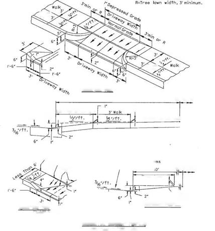
For tree lawns less than 6 ft (1.8 m) wide, Fig. 2.51 shows the profile treatment. Clearance for the design vehicle is achieved by depressing the sidewalk 1 in (25.4 mm) at the driveway. The sidewalk cross slope of % in/ft (2.1%) is retained. The design may be used directly with curbed highways having cross-section criteria as listed above and the profile conditions of Fig. 2.50. For other cross sections, a template of the design vehicle may be used to design the profile.

Figure 2.51 shows an isometric view and profile for a driveway where only a 3-ft (0.9-m) tree lawn is available. This design is shown not because it is desirable, but because right-of-way width and property development may require this type of design. Whenever feasible, the tree lawn should be 8 ft (2.4 m) or wider. Where the total width of tree lawn and sidewalk is less than 6 ft (1.8 m), the minimum 3-ft (0.9-m) apron designs are inappropriate and cannot be used, as they extend curb or sharp flares into the sidewalk area. For this condition, the sidewalk and curb are transitioned to meet the drive profile as shown on the lower portion of Fig. 2.51. The profile of the drive meets the 1-in (25.4-mm) depressed grade of the sidewalk, as shown in the drive profile.

The tree lawn and walk design shown in Figs. 2.50 and 2.51 will keep storm water, flowing at the curb design height or less, from flowing over the sidewalk. If it is nec­essary to lower the curb and sidewalk more than 1 in (25 mm), the drainage condition should be checked thoroughly.

Commercial drive profiles usually use a dropped curb across the approach. However, some commercial drives serving large traffic generators may be designed as at-grade intersections, without dropped curbs, because of their high traffic volumes.

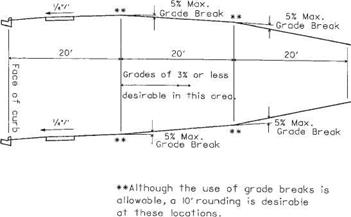
Figure 2.58 shows the recommended grade controls for commercial driveways. The grade should be as flat as possible and still meet drainage requirements. The 20-ft

Drive Profile Design

FIGURE 2.58 Profiles for commercial drives. Conversions: 1 ft = 0.305 m, 1/4 in/ft = 21 mm/m. (From Location and Design Manual, Vol. 1, Roadway Design, Ohio Department of Transportation, with permission)

Drive Profile Design

FIGURE 2.59 Commercial design vehicle showing wheel spacings and clearances. Conversions: 1 ft = 0.305 m, 1 in = 25.4 mm. (From Location and Design Manual, Vol. 1, Roadway Design, Ohio Department of Transportation, with permission)

(6.1-m) length between grade breaks is required by the low clearance and the long axle spacing of the commercial design vehicle shown in Fig. 2.59. Tree lawn profile design should be in accordance with Figs. 2.50 and 2.51. The grade break at the face of the curb is critical for some commercial vehicles, and the cross-section requirements for residential drives on curbed streets should be used.

Shopping Center and Industrial Drives

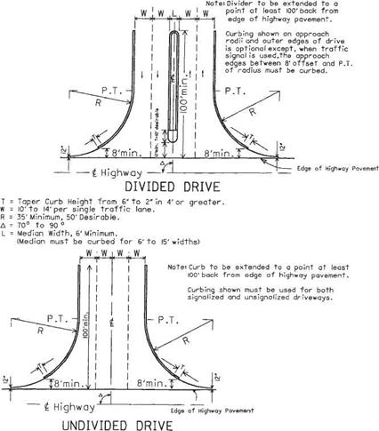
Figure 2.57 shows two typical driveway designs to be used as a guide for the design of driveways serving high-volume traffic generators such as shopping centers, industrial plants, industrial parks, and other types of developments having similar traffic charac­teristics. Many of the design features discussed in Art. 2.4.1, At-Grade Intersections, are applicable here. Geometric considerations are as follows:

• Driveways should intersect the highway at an angle between 70 and 90°.

• Each driveway traffic lane should have a minimum width of 10 ft (3.0 m), with 12 ft (3.7 m) preferred.

Shopping Center and Industrial Drives

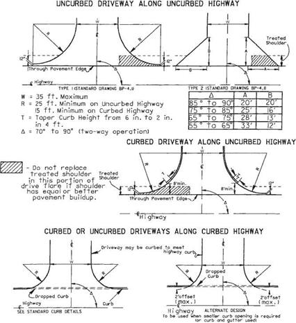
FIGURE 2.56 Designs for commercial drives. Conversions: 1 ft = 0.305 m, 1 in = 25.4 mm. (From Location and Design Manual, Vol. 1, Roadway Design, Ohio Department of Transportation, with permission)

• Major driveways in shopping centers should be constructed to prevent cross movement of internal traffic within 100 ft (30 m) of the entrance approach. This may be accomplished by use of a raised divider 6 in (150 mm) high, 6 ft (1.8 m) wide (minimum), and 100 ft (30 m) long, and/or by use of curbing, sidewalk, or other bar­rier along the drive edges for a length of 100 ft (30 m).

• Driveways designed for traffic signal operation should have curbed radii and should provide a minimum of two lanes for vehicles entering the highway.

Commercial Drives

The access requirements of most commercial developments can be served by driveways having standard design characteristics. The exceptions are driveways having high traffic volumes, those being used by large vehicles, or those serving businesses that engender unique traffic patterns. For standard commercial drive designs, see Fig. 2.56. The recom­mended radii are (1) 15 ft (4.6 m) minimum, when the through highway is curbed, and (2) 25 ft (7.6 m) minimum, when the through highway is uncurbed. The maximum width is 35 ft (11 m). A dropped curb should be used on curbed streets as shown in section B-B in Fig. 2.50.

Commercial Drives

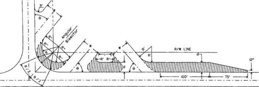
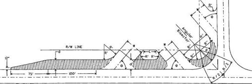
L 15 ft. or greater.


W Not greater than 35ft.

Є 45° to 90°


Подпись: 189

R Intersection Radius – Use 40’minimum when existing radius is less than 40′. R’ Nonturning Radius, 5’min., 10’maximum.


Commercial Drives

Commercial Drives

Подпись: 190
Подпись: FIGURE 2.54 Design for service station drives with uncurbed roadway and curbed approach. Conversions: 1 ft = 0.305 m, 1 in = 25.4 mm. (From Location and Design Manual, Vol. 1, Roadway Design, Ohio Department of Transportation, with permission)Commercial DrivesL 6ft. or greater W Not greater than 35 ft.
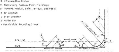
-9- 45° to 90°

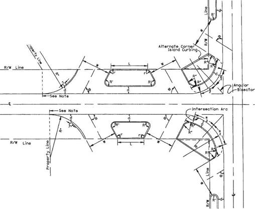
R Intersection Radius – Use 40′ minimum when existing radius is less than 40′. R’Nonturning Radius, 3’to 5′

R’Turning Radius, 3’min. – Larger radius desirable T Taper Curb Height from 6in. to 2in, in 4ft.

d 8ft. to 10ft. offset (Paved with eame material as approaches)

Подпись:
6ft. offset may be used at Truck Stops to discourage parking r Permissible rounding 3’to 5′

Commercial Drives

Подпись: Standard Curb Return Detail Curb carried through arc of approach radius * When R is less than 40′, use 20′ min. When R is between 40′ & 80’use R/2. When R is greater than 80′, max. need not be more than 40′.
Commercial Drives
Commercial Drives

ALTERNATE CURB RETURN DETAIL

FIGURE 2.55 Design for service station drives with curbed roadway and curbed approach. Conversion: 1 ft = 0.305 m. (From Location and Design Manual, Vol. 1, Roadway Design, Ohio Department of Transportation, with permission)

Where access requirements are such that a nonstandard driveway is necessary, the design may approximate the design of shopping center driveways, to be discussed in Art. 2.10.6, or that of a public road intersection. Specially designed radii and a width greater than 35 ft (11 m) may be permitted, as necessary, to accommodate the type of vehicle using the driveway. For example, a truck stop may require two one-way drive­ways, or a single drive with width greater than 35 ft (11 m), and radii as great as 75 ft (23 m) to facilitate turning movements. See Ref. 12.

Service Station Drives

Service station drive approach geometry is probably the most complex of any drive design. Many of the geometric features may be used in the design of other commercial

–у* I—w-12’* —14’ж |—-

Service Station Drives


NOTES

GENERAL’. The design details shown hereon shall govern the constraction of driveways unless otherwise shown in /he project pton$.

The pavement type and l hickness Shalt be specified In the project plans.

Driveway ond malt box approaches shall be combined when feasible.

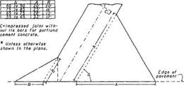
JOINTS: impressed Joints for

portlond cement concrete drive­ways shall be minimum width by J" і depth and shall be seated with 705 01 or ASTM 0 ‘850.

In addition lo the Joints shown hereon. Impressed Joints without tie bars sholi be placed in portlond cement concrete driveways ot Intervals not to exceed seventeen feel In the portion of the driveway back of the flare.


TYPE I DRIVEWAY


Подпись: 185

COMBINED DRIVEWAY & MAIL BOX APPROACH


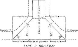
TYPE 2 SKEWED DRIVEWAY

Transition from standard curd section to drop curb section to be made In 18" distance from driveway.

s—Dr ivewgy


BUREAU OP LOCATION AND DESIGN OHIO DEPARTMENT OF TRANSPORTATION

DRIVEWAYS

0 Ate

2-2i-SZ

c‘"x?£’h bp-4.1

iPPRnven^X fur. R.. 1 * 0


Service Station Drives

** Add J feet і or coch additional mall box

TYPICAL MAIL BOX APPROACH


Service Station DrivesService Station DrivesService Station DrivesService Station DrivesService Station Drives

Service Station Drives

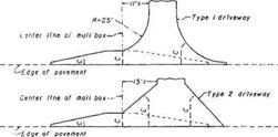
FIGURE 2.50 Details of driveway designs. Conversions: 1 ft = 0.305 m, 1 in = 25.4 mm. (From Location and Design Manual, Vol. 1, Roadway Design, Ohio Department of Transportation, with permission)

and industrial drives. Figures 2.52 through 2.55 illustrate service station approach designs under varying conditions.

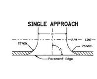
The location and angle of an approach in relation to an adjacent highway intersection should be such that a vehicle entering or leaving the site may turn out of or into the nearest lane of traffic moving in the desired direction and be channeled within this lane before entering the intersection or proceeding along the highway. The interior angle between the axes of dual approaches and the centerline of the roadway should fall between 45 and 90°. This interior angle should fall between 70 and 90° for single approaches designed for two-way operation. The width of all approaches should not be greater than 35 ft (11 m) in the throat of the approach measured at right angles to

Подпись: ISOMETRIC VIEW

Подпись: Various Gutter Slopi Up to t'/ft. ' . и Подпись: Use Grade Controls (Drive Details *l)

Service Station Drives
Подпись: ALTERNATE: DRIVE WITHOUT CURB
Подпись: ISOMETRIC VIEW
Подпись: Use Grade Controls (Drive Details *)

Service Station DrivesEXAMPLE: TREE LAWN AND WALK, LESS THAN 6′ WALK DEPRESSED Г
RESIDENTIAL DRIVEWAY PROFILES

LESS THAN 6′ TREE LAWN

FIGURE 2.51 Additional details of driveway designs. Conversions: 1 ft = 0.305 m, 1 in = 25.4 mm. (From Location and Design Manual, Vol. 1, Roadway Design, Ohio Department of Transportation, with permission) the axis of the approach. Where public alleys adjoin the service station property, approaches may begin at the far side of the alley, and if so used, the width of the alley should be included as part of the approach opening.

Approach radii on uncurbed highways should be as follows:

Turning radii: 15 ft (4.6 m) minimum, 25 to 50 ft (7.6 to 15.2 m) desirable Nonturning radii: 5 ft (1.5 m) minimum, 10 ft (3.0 m) maximum

Approach radii on curbed highways should be as follows:

Turning radii: 3 ft (0.91 m) minimum, 15 to 25 ft (4.6 to 7.6 m) desirable Nonturning radii: 3 ft (0.91 m) minimum, 5 ft (1.5 m) maximum

L 15′ or greater W 35′ maximum

Service Station DrivesЛ 70° to 90° (for approach with two-way operation) – O 45° to 90°

R’ Nonturning Radius,

5′ min. to!0′ max R" Turning Radius, 15’min,

25’to 50’Desirable r Permissible Rounding 15’max ч\\ Treated Shoulder

Service Station Drives
DUAL APPROACHES & INTERMEDIATE ISLAND

Where the approach radius controls the turning radius of a right-turning vehicle entering the service station from the adjacent traffic lane of the roadway, the radius of that edge should be as long as practical to provide a free and safe movement.

Urban Residential Drives

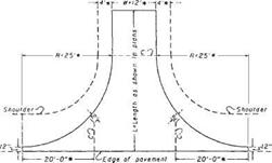
Either type 1 or type 2 drives (Fig. 2.49) may be used in urban areas. If used in urban areas, the radius and flare dimensions may be reduced so that the apron does not extend past the back of the sidewalk, or past the right-of-way line if there are no sidewalks. The desirable minimum radius for type 1 drives, when the through highway is curbed, is 15 ft (4.6 m).

Three methods are shown in Fig. 2.50 for designing driveways between the curb line and sidewalk to provide for turning vehicles. Other designs may be used if they are approved for use by the local governmental agencies responsible for maintenance of the project. Additional details are shown in Fig. 2.51 when the tree lawn is less than 6 ft (1.8 m). Residential drives on curbed streets should use a dropped curb as shown in section B-B of Fig. 2.50.

Rural Driveway Geometries

Rural residential drives and field drives should normally conform to the type 1 design shown in Fig. 2.49 (Ref. 14). New drives should intersect the highway at an angle between 70 and 90°. In some cases, however, it may be necessary to retain existing drive angles that vary from these desirable angles.

If the project involves existing drives, the existing width is normally retained unless it is less than 12 ft (3.7 m). In that case, it should be widened to provide a 12-ft (3.7-m) throat width. In the case of new drives, the width should normally be 12 ft (3.7 m). If the new driveway is a combined drive between two properties, the width should nor­mally not exceed 24 ft (7.3 m). Also, a wider field drive may be used if it will keep a farm equipment operator from encroaching on the opposing traffic lane when entering or exiting the highway.

The radius of the type 1 driveway should normally be 25 ft (7.6 m). The radius may be increased on field drives if it is deemed that the larger values will improve dri­veway operation and reduce the hazard to motorists and farm equipment operators.

Driveways abutting uncurbed highways may be curbed. However, the curb should not extend closer to the through pavement edge than 8 ft (2.4 m) or the treated shoulder width, whichever is greater. This is recommended to avoid curb obstruction for vehicles, snowplows, etc., using the shoulder.

DRIVEWAY DESIGN

1.10.1 Location

Part of the process in obtaining a driveway permit is to determine where the driveway will be located. The following guidelines may be used to establish this location.

Wherever possible, drives should be located in accordance with the intersection sight distance criteria (see Table 2.3). Special consideration should be given to the location of drive access to high-volume traffic generators such as shopping centers and industrial plants and parks, as well as other types of development having similar traffic characteristics. These should be treated as standard intersections with appropriate spacing to the nearest intersection. A driveway serving all directions of traffic should be located a minimum of 600 ft (183 m) from the nearest major highway or street inter­section. A new driveway should not be located where it will create an offset intersection opposite an existing street, highway, or major commercial driveway.

Establishing Access Control

Access control may be exercised and established by statute—through zoning ordinances, driveway controls, and turning and parking regulations—and by geometric design. Control by statute is used where full access control or a high degree of access control is required. Direct driveway connections may be prohibited, and at-grade intersections may be allowed only with major crossroads. This may be employed for a major urban arterial.

Zoning can control the type of property development adjacent to the roadway, and thereby influence the amount and type of traffic generated in the area. Property uses can be limited to those that attract very few people, excluding those that would generate significant volumes of traffic during hours of peak movement. Zoning regulations can require off-street parking provisions as a condition for permit approval.

Driveway controls can be effective in preserving the functional character of the roadway. On arterials in built-up urban areas, it is important to establish minimum spacing requirements for driveways, as well as the minimum distance from a driveway to the nearest intersection.

An example of geometric design to control access is the use of a frontage road to provide indirect access of abutting properties to a major arterial. Also, the use of a raised concrete median strip in the center of the road can effectively prohibit left turns into or out of driveways.

ACCESS TO PUBLIC ROADS

2.9.1 Defining Access Control

Control of access is the condition where the right of owners or occupants of abutting land to access a highway is fully or partially controlled by public authority. Access control is usually defined by regulations of the authority having jurisdiction over the roadway. The purpose of establishing access control is to provide for the safe and expeditious movement of vehicles on the street or highway, while upgrading the level of service and safety to those living near and using the facility. Regulations may be categorized as full control of access, partial control of access, and driveway and approach regulations.

Full control of access is the means by which preference is given to through traffic by providing access connections only at selected public roads and by prohibiting at – grade crossings and direct private driveway connections. Partial control of access still gives preference to through traffic, but allows some at-grade crossings and some drive­way connections. Driveway or approach regulations may apply where no control of access is obtained. Each abutting property is permitted access to the street or highway, but the location, number, and geometrics of the access points may be governed by the regulations.