Category HIGHWAY ENGINEERING HANDBOOK

SERVICE ROADS

Service roads, or frontage roads, as they are sometimes called, are used to enhance capacity on the mainline, control access, serve adjacent properties, or maintain traffic circulation. They permit development of adjacent properties while preserving the through character of the mainline roadway. Service roads may be either one-way or two-way, depending on where they are located and the purpose they are intended to serve.

Although the alignment and profile of the mainline may have an influence, service roads are generally designed to meet specific criteria based on functional classification (usually “local”), traffic volumes, terrain or locale, and design speed. Two features, however, are unique to service roads and are further discussed below. They are (1) the separation between the service road and mainline and (2) the design of the crossroad connection.

The farther the service road is located from the mainline, the less influence the two facilities will have on each other. A separation width that exceeds the clear zone mea­surement for each roadway is desirable. However, the separation should be at least wide enough to provide normal shoulder widths on each facility, and also to accom­modate surface drainage and a suitable physical traffic barrier. Glare screen is desirable to screen headlights when the service road is two-way.

At intersections with crossroads to the mainline, the distance between the mainline and service road becomes critical. This distance should be great enough to provide adequate storage on the crossroad approach lanes to both the mainline and service road. The recommended minimum distance between the mainline and service road pavement edges is 150 ft (46 m) in urban areas and 300 ft (91 m) in rural areas. In addition, the designer should check the adequacy of stopping sight distance on the crossroad as well as intersection sight distance at the service road.

Подпись: 182

Determine taper length

SERVICE ROADS


SERVICE ROADS

TYPE C-TAPERED

SERVICE ROADS

TYPE D-ON CURVE

Multilane Exit Ramps and Diverging Roadways

Figure 2.47 shows recommended designs for multilane exit ramps and diverging roadways. A diverging roadway is defined as a single roadway that branches or forks into two separate roadways without the use of a speed change lane.

Class I and II diverging roadways should be used when either or both the diverging roadways are mainline roadways of an expressway or a freeway. Class III diverging road­ways should be used at the divergence of directional ramps within an interchange or at the divergence of ramps with non-limited-access roads or streets. In general, class III is applicable at all locations other than those requiring class I or class II.

Lane Balance and Continuity. To have lane continuity, the number of mainline lanes leaving the diverging nose must be equal to the number of mainline lanes approaching the nose. The total number of lanes leaving the diverging nose (mainline lanes plus diverging lanes) must be 1 greater than the total number of lanes approaching the nose to obtain lane balance. The purpose of obtaining lane continuity and lane balance is to avoid a drop lane situation.

It may be necessary to obtain lane balance by adding additional lanes upstream from the diverging nose. The length of each additional lane should be 2500 ft (762 m) and should be introduced using a 0- to 12-ft (3.7-m) taper of 100 ft (30 m) as recom­mended in Fig. 2.47 for the approach roadway class and design speed. There may be conditions off the mainline, such as on collector-distributor roads or within inter­changes, where lane balance and continuity are less important. In such cases, the spe­cial diverging roadway design shown in Fig. 2.47 b may be used.

Terminal Design. The design of diverging roadway terminals is determined by the class and design speed of the approach roadway, and is based on the required neutral gore length L and the required nose width N. Figure 2.47 includes recommended length L and nose width N for various design speeds in diverging roadway classes.

Horizontal Curvature. The inset table in Fig. 2.47 lists recommended values for the diverging curvature (curve differential) between the outer pavement edges of diverging roadways. These values apply only when the alignment between the diverging nose and the PC of the diverging curvature is on tangent or simple curvature. When compounded or spiral curvature is used in the diverging area, it will be necessary to design diverging roadway alignments individually to provide proper L and N for the approach roadway class and design speed.

Multilane Exit Ramps and Diverging Roadways

FIGURE 2.47 Designs for multilane exit ramps and converging roadways. Conversions: 1 mi/h = 1.609 km/h, 1 ft = 0.305 m. (From Location and Design Manual, Vol. 1, Roadway Design, Ohio Department of Transportation, with permission)


Подпись: 180

Crest Vertical Curves. When a diverging nose is located on a crest vertical curve, the curve should be designed using the design speed of the approach highway and a stopping sight distance value 25 percent higher than shown in Table 2.18.

Superelevation and Joint Location. The superelevation rate should be based on the design speed of the approach roadway. Superelevation in the terminal area should be designed in accordance with the guidelines given for single-lane ramp terminals (Art. 2.5.2). Longitudinal joints should be located so they will coincide with and define the lane lines.

2.7.2 Four-Lane Divided to Two-Lane Transition

Figure 2.48 shows a reversed curve design (types A and B), a tapered design (type C), and a design for a transition on a curve (type D) for achieving a four-lane divided to two-lane transition. The pavement transition should be located in an area where it can easily be seen. Intersections or drives should be avoided in the transition area. Vertical or horizontal curves should provide preferred stopping sight distance. Reverse curve transitions should normally be used for median widths of 20 ft (6 m) or wider. Taper lengths are based on the design speed of the mainline and are calculated from Eq. (2.5).

MULTILANE RAMP AND ROADWAY TERMINALS AND TRANSITIONS

When two roadways converge or diverge, the less significant roadway should exit or enter on the right. Left-hand exits or entrances are contrary to driver expectancy and should be avoided wherever possible.

2.7.1 Multilane Entrance Ramps and Converging Roadways

Figure 2.46 shows recommended designs to be used for multilane entrance ramps and converging roadways. Converging roadways are defined as separate and nearly parallel roadways or ramps that combine into a single continuous roadway or ramp having a greater number of lanes beyond the nose than the number of lanes on either approach roadway. High-speed and low-speed entrance terminals should be used in lieu of converg­ing roadway drawings when applicable. High-speed converging roadways should be used when either or both of the converging roadways are mainline roadways of an expressway or a freeway. Low-speed terminals should be used at the convergence of directional ramps within an interchange or at the convergence of interchange ramps with non-limited-access roads or streets. In general, low-speed terminals are applicable at all locations other than those requiring the use of high-speed terminals.

Lane Balance and Continuity. To avoid inside merges, the number of mainline lanes plus converging lanes approaching the nose must be equal to the resultant number of lanes leaving the nose. To make this possible, it is often necessary to carry additional mainline lanes past the nose for an adequate distance prior to tapering back to the desired number of lanes. These details are shown in Fig. 2.46.

Preferential Flow. In Fig. 2.46, one roadway in each design is labeled “preferential flow.” This indicates the more important of the two approaching traffic flows. In selecting the preferential flow, a designer must consider the effect of traffic volumes, number of lanes, the continuity and importance of signed routes, vehicle speeds, and roadway alignment. Lanes carrying the preferential flow are given the higher design treatment. When it is necessary to reduce a number of converging lanes or where an angular change in direction must occur, the design should favor the preferential flow.

Horizontal Curvature. Horizontal curves of roadways approaching the terminal nose should conform to mainline roadway criteria in the case of mainline roadways and to ramp entrance terminal criteria in the case of ramps.

MULTILANE RAMP AND ROADWAY TERMINALS AND TRANSITIONS

Expontlor – {S —————–

Contraction ©


Подпись: 176

MULTILANE RAMP AND ROADWAY TERMINALS AND TRANSITIONS

2

Подпись: 177 MULTILANE RAMP AND ROADWAY TERMINALS AND TRANSITIONS

LANE EXIT FROM 4 LANES

TABLE A


MULTILANE RAMP AND ROADWAY TERMINALS AND TRANSITIONS

SINGLE LANE CONVERGING WITH MUL T/-LANE


MULTILANE RAMP AND ROADWAY TERMINALS AND TRANSITIONS

MUL TI-LANE CONVERGING WITH MUL TI-LANE


MULTILANE RAMP AND ROADWAY TERMINALS AND TRANSITIONS

Подпись: 178* Not9* the number of tones leaving the converging nose must be equal to the total nuntber of tones (converging plus main I line I approaching the nose.

MULTILANE RAMP AND ROADWAY TERMINALS AND TRANSITIONS

Distance. Avoidance Maneuver C or E. os per Figure 201-6.


Crest Vertical Curves. Crest vertical curves on constant-width roadways approaching the merging nose should be designed to provide sight distance consistent with the design speed of the roadway. Crest vertical curves from the merging nose forward to a point where pavement convergence ceases, and to the converging portion of an approaching roadway where the number of lanes is being reduced in advance of the nose, should be designed using stopping sight distance values 25 percent higher than shown in Table 2.18. When design speeds differ on approaching roadways, the higher of the two design speeds should be used in designing the crest vertical curve beyond the merging nose.

Superelevation and Joint Location. Superelevation in the terminal area should be designed in accordance with the guidelines given for single-lane ramp terminals. Longitudinal joints should be located so they will coincide with and define the lane lines.

COLLECTOR-DISTRIBUTOR ROADS

Collector-distributor (C-D) roads are used to minimize weaving problems and reduce the number of conflict points (merging and diverging) on the mainline. C-D roads may be used within a single interchange, through two adjacent interchanges, or continuously through several interchanges.

2.6.1 Design of C-D Roads

When a C-D road is provided between interchanges, a minimum of two lanes should be used. Either one or two lanes may be used on C-D roads within a single interchange. The cross-section elements for one – and two-lane C-D roads should be in accordance with the criteria for one-lane and two-lane directional roadways provided in Fig. 2.27. The separation between the mainline and C-D road pavements should be designed to prevent, or at least discourage, indiscriminate crossovers. As a minimum, the separa­tion should be wide enough to provide normal shoulder widths for both the mainline and C-D road roadways plus a suitable median. Normally, a standard concrete barrier median is used, since C-D road separation often involves obstructions such as bridge parapets, piers, or overhead sign supports. There may be isolated cases where a lesser – type median may be used.

Подпись: 174COLLECTOR-DISTRIBUTOR ROADS

2.6.2 C-D Road Entrance and Exit Terminals

Figure 2.45a shows both high-speed and low-speed C-D road entrance terminals. The high-speed collector-distributor entrance terminal is intended for use on rural inter­state highways and other freeways where high-speed design has been designated. The low-speed collector-distributor entrance terminal is intended for use on all other freeways. Three exit terminal lane conditions are shown on Fig. 2.45b. These terminal designs are to be applied to highways using either high-speed or low-speed terminals.

Superelevation at C-D terminals should be developed similar to that prescribed for standard ramp terminals.

Terminals on Crest Vertical Curves

Mainline crest vertical curves in the vicinity of ramp terminals should be designed using stopping sight distance values 25 percent higher than the design speed value from Table 2.18. Where a crest vertical curve occurs on an exit ramp at or near the nose, the crest vertical curve should be designed using the “upper-range” design speeds of Table 2.28.

2.5.2 Ramp At-Grade Intersections

Ramp at-grade intersections are designed using many of the same criteria as outlined in Art. 2.4.1. However, one of the basic differences is the one-way nature of ramps and the fact that most traffic at ramp intersections is turning. Figure 2.44 shows the design of a typical uncurbed ramp intersection. Curbed returns are normally used in urban areas where space is more restricted.

Superelevation at Terminals

Superelevation at ramp terminals should be developed using the following guidelines. The rate of superelevation at the entrance and exit nose should be selected on the basis of the design speed of the ramp at the nose. All transverse changes or breaks in superelevation should be made at joint lines in concrete pavement. In the case of bituminous pavement, the superelevation breaks should occur in the same locations as they would in concrete pavement. For high-speed terminals, the transverse breaks in superelevation cross slope should not exceed a differential of 0.032 ft/ft (0.032 m/m) at the mainline pavement edge or 0.050 ft/ft (0.050 m/m) at other locations. When a double break occurs on longitudinal joints less than 6 ft (1.83 m) apart, it should not exceed a total differential of 0.032 ft/ft (0.032 m/m), if adjacent to the mainline, or 0.050 ft/ft (0.050 m/m) elsewhere. On low – speed terminals, the transverse breaks in superelevation cross slope should not exceed a differential of 0.05 to 0.06 ft/ft (0.05 to 0.06 m/m). For high-speed terminals, the rate of rotation of a superelevated ramp pavement or speed change lane pavement should be in accordance with rates from Table 2.13. Where possible, the terminal area pavement and shoulder should slope away from the mainline pavement so that a minimum amount of water drains across the mainline pavement.

Single-Lane Ramp Terminals

A ramp terminal is the portion of a ramp adjacent to the through lane on the mainline. It includes both the taper and the speed-change lane. Ohio has recently revised its ter­minal criteria and uses two basic terminal classifications:

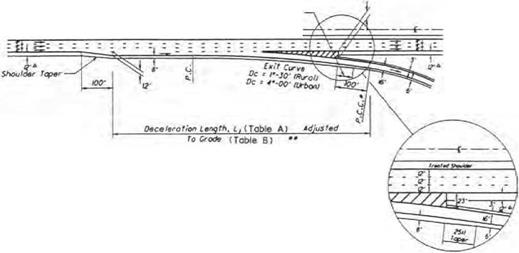
High-speed terminals are intended for use on all facilities with a design speed of 50 mi/h (80 km/h) or higher. They are used in both rural and urban locales. Figure 2.41 shows the details for high-speed single-lane entrance terminals. This terminal is a taper-type design for the last 1250 ft (381 m), tapering from a 25-ft (7.6-m) offset from the mainline to zero. Tables A and B in Fig. 2.41 provide information for designing the length of the terminal to provide adequate distance for entering vehicles that matches or nearly matches the design speed of the mainline. This must be achieved by the time the terminal narrows to 12 ft (3.7 m) in width (see Fig. 2.41). Figure 2.42 provides design information for high-speed single-lane exit terminals that are used in both rural and urban locales. In the urban environment, a sharper departure curve is permitted for the exit curve, which allows for a slower speed exit. Once again, Tables A and B are provided in Fig. 2.42 to determine the proper termi­nal length based on mainline speed, first curve speed, and vertical grade adjustment.

Single-Lane Ramp Terminals

* lanijth Stay За fncraassd Far Sup*rm ft *o т гол Transition +* To Do tor mint Lp. Sub f roc t is Ana Lt Fro» i„

* + + ІЛаШіпа pawad shouldtr width os rtqvi’td by

Подпись: 167
л*о r*j For Si/ufft Ian* £t1raoct Тагмілаіш

L Tht minimum accolorotiaa tangth* і &ho! t b* It *■ Lt.

2. Tht 9r to 2У woriab/t rid lb of trtoftd shootdar of Ihs *n franco tor mine I stroll bt s/apsd for 12′ as raqvirtd for яоіпііщ da sign /у*иоііу j£jm. Sft+l tectpt (or tha tost /00′ to 200′ at ths 9′ and. which It to b* stopmd os rtparrtd for praptr tarm/not grading.

X Normally sing ft font romps *гШ ho r# о width pf t6 Ths width shat! bo incr+ostd to whan th r romp гв^у)

is lass than 200′. ШЬ»л an /S’ w ids romp »j mod. ths 25* oatroac-щ tarminot width shaft to rtfoinad and th* 9‘ width rodvcod by 2*.

A. if tp tparoflol isngtht is not ropairod H f- S50*L than th» 2QQ" minimum spiral shootd b* tango* t to ths SOft Гарт

Uo in line Design Speed. V (mph)

Acceleration length, L (ft) for design speed of lost romp curve, Vr (mph)

Stop

IS

20

25

30

35

40

45

50

SO

720

660

610

550

450

350

130

55

960

900

810

780

670

550

320

150

60

1200

1140

1100

1020

910

800

550

420

180

65

1410

І350

1310

1220

1120

1000

770

600

370

70

1620

1560

1520

1420

1350

1230

1000

820

580

TABLE B High-speed entrance terminal adjustment factors as a function of grade

Mainline Design Speed (mph)

Ratio of length on grade to length on level for design speed of lost romp curve ImphJn

20

25

30

35

40

45

50

AH Speeds

3 to 4X upgrade

3 to AX downarode

50

1.30

1.35

1. 40

1.40

1.40

0.65

55

1.35

і 40

1.45

1.45

1.45

0.625

60

1.40

1.45

1.50

1.50

1.50

1.55

1.60

0.60

65

1.45

1.50

1.55

1.55

1.60

1.65

1. 70

0.60

70

1.50

1.55

1.60

1.65

I. 70

1.75

ISO

0.60

5 to 6X upgrade

5 to 6X downarode

50

1.50

1.60

1. 70

1.80

1.90

0.55

55

1.60

1. 70

1.80

1.90

2.05

0. 525

60

1. 70

1.80

1.90

2.05

2.20

2.35

2.50

0.50

65

1.85

1.95

2.05

2.20

2.40

2.60

2. 75

0.50

70

2.00

2.10

2.20

2.40

2.60

2.80

3.00

0.50

No adjustment required for grades less than 3X.

* Ratio from this table multiplied by acceleration length inTobfeA gives occeierotion length on grade.

The ‘’grade" in the table is the overage grade measured over the distance for which the occe ter at ion length applies.

FIGURE 2.41 High-speed single-lane entrance terminal. Conversions: 1 mi/h = 1.609 km/h, 1 ft = 0.305 m. (From Location and Design Manual, Vol. 1, Roadway Design, Ohio Department of Transportation, with permission) (Continued)

• • The Угпітит Deceleration Length, L, After Adjustment for Gradet

Подпись: 169Подпись:Подпись:Подпись:Подпись:Single-Lane Ramp Terminals

Подпись: first Ramp Curve Design Speed, vr cmiihj •••

Table B, S^xj// Be 600′

• •• Or Other Design Speed Li/nitlnq Geometric Control Such As The Stopping
Sight Distance for A Vertical Ctxve Or The воск Of A Traffic Oueoe.

* uainline paved shoulder width os retired by ТсЫе 2.22 Of 223.

Notes for Single-Lone Exit Terminals

1. The Exit Cirve should nor mol I у be Г-JO’ (RuroU or 49-00′ (Jr bon) where The mainline is on Tangent. Where the mainline is on curving alignment, the maximum differential between the Exit Curve and the mcinline curve should normally

be f-JO’ iRuroll or 49-00‘ IUrbant. This differential. however, moy vary by as much os one degree in order to

ovoid a tangent exit oligrvr>ent. (See Section SOJ.6.4 for The oliowoble tronsverse breaks in superelevation cross-slope.>

2. When the First Ramp Curve does not exceed в9, the Exit Curve moy be compounded directly with the first Romp Ciwe ot a RCC КЮ’ beyond the nose. When the first Ramp Curve does exceed 69, c spiral should be placed between the Exit Curve and the first Ramp Curve and the beginning of the spiral (CS) should be ot the nose.

J. Normally single lone romps will hove a width of (S’. The width shall be increased to Ш’ when the ramp rod>us is lass than 200′. when an I6‘ wide romp Is used, the J9′ exit Terminal width shall be retained and the 2J’ width reduced by 2‘.

Mo in line Design Speed. V (mph)

Deceleration length, L (ft) for design speed of first ramp curve, Vr (mph) ***

Stop

15

го

25

30

35

40

45

50

50

435

405

385

355

315

265

225

175

55

460

455

440

410

380

350

285

235

60

530

500

480

460

430

405

350

300

240

65

570

540

520

500

470

440

390

340

■280

70

615

590

570

550

520

490

440

390

340

Подпись: Mointin9 Design Speed. (V)

0 P. C.C. Or Mid-Point of 200′ Spiro I

00 Th» Minimum Deceltrotion Length, L. After Adjustment For Grode (Table В ) fS BOO*

000 Or Other Design Speed Limiting Geometric Control Such As The Stopping
Sight Distance For A Verticol Curve Or The воск Of A Troffic Queue.

TABLE B High-speed exit terminal adjustment factors as a function of grade

Mainline Design Speed (mph) •

Ratio of length on grade to length on level for design speed of first ramp curve (mph)*

AH Speeds

All Speeds

3 to 4X upgrade

3 to 4X downgrade

AH Speeds

0. 90

1.20

5 to 6X upgrade

5 to 6X downgrade

All Speeds

0.80

1.35

No adjustment required for grades less thon 3X.

* Ratio from this table mult ip tied by dece lerot ion length in Table A gives dece lerot ion length on grade.

The ‘grade" in the toble is the average grade measured over the distance for which the dece lerot ion length applies.

FIGURE 2.42 High-speed single-lane exit terminal. Conversions: 1 mi/h = 1.609 km/h, 1 ft = 0.305 m. (From Location and Design Manual, Vol. 1, Roadway Design, Ohio Department of Transportation, with permission) (Continued)

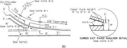
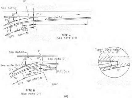
Low-speed terminals are intended for use on highways that have little or no access control except through an interchange area. Many of the features of low-speed terminals are applicable to a terminal of one ramp with another ramp in complex interchanges. Low-speed terminals are also used with collector-distributor roads. Figure 2.43 and Table 2.29 provide design details for low-speed terminals.


Single-Lane Ramp Terminals

Curb


CURBED ENTRANCE
PAVED SHOULDER DETAIL


Shoulder 7


Single-Lane Ramp Terminals

FIGURE 2.43 Low-speed ramp terminals. (a) Entrance terminals. (b) Exit terminals. See Table 2.29 for notes. Conversions: 1 ft = 0.305 m, 1 in = 25.4 mm. (From Location and Design Manual, Vol. 1, Roadway Design, Ohio Department of Transportation, with permission)


Single-Lane Ramp Terminals

TABLE 2.29 Design Notes for Low-Speed Entrance and Exit Terminals

See Fig. 2.43

A. General

1. Low-speed terminals are intended for use on highways which have little or no access con­trol except through an interchange area. Many of the features of low-speed terminals are applicable to a terminal of one ramp with another ramp in a freeway interchange.

B. Exit terminal

1. The curve differential between the through roadway and exit curve DC1 may vary from a minimum of 4° to the maximum allowable differential.

2. Exit curve DC1 may be either compounded or spiraled into ramp curve Dc2.

C. Entrance terminal: type A and type B

1. Type A is preferred and shall normally be used; however, when a ramp enters as an added lane or as a combined acceleration-deceleration lane, type B may be used if its use would result in a substantial savings in cost (i. e., reduced bridge width).

2. The acceleration lane of type A shall be a uniform taper (35:1) relative to the through pavement edge for either tangent or curving alignment.

3. The curve differential between the through roadway and entrance curve Dc5 of type B shall be 4°.

4. The design of the entrance terminal shall be based on the following:

(a) Ramp curve Dc3 of 8° or less. When the through roadway is on a tangent or a curve to the right, Dc4 shall be a 150-ft-long simple curve of a degree such that the differen­tial between it and the through roadway will not exceed 4°. When the through road­way is on a curve to the left, a 150-ft tangent shall be substituted for Dc 4.

(b) Ramp curve Dc3 greater than 8°. A 150-ft spiral shall be substituted for Dc4.

D. Ramp width

1. Normally, single-lane ramps will have a width of 16 ft. The width shall be increased to 18 ft when the ramp radius is less than 200 ft. When an 18-ft-wide ramp is used, the 35-ft exit and 20-ft entrance terminal widths shall be retained and the 19- and 4-ft widths reduced 2 ft.

E. Treated shoulder

1. The width of the treated shoulders along the speed change lane shall be as shown in Fig. 2.25.

2. If the ramp or through roadway has a curb offset greater than 6 ft (or 3 ft) the greater width shall be used at the terminal. Retain the 19-ft width.

3. The special detail drawings shall apply when the through roadway is curbed.

F. Left side terminals

1. Left side entrance and exits shall be designed similarly to the drawing shown, but of opposite hand.

Conversion: 1 ft = 0.305 m.

Source: Location and Design Manual, Vol. 1, Roadway Design, Ohio Department of Transportation,

with permission.

INTERCHANGE RAMP DESIGN

An interchange ramp is a roadway that connects two legs of an interchange. Ramp cross­section elements are discussed in Art. 2.3, Cross-Section Design. Elements contributing to horizontal and vertical alignments are designed similar to any roadway once the ramp design speed has been determined.

2.5.1 Ramp Design Speed

To design horizontal and vertical alignment features, a design speed must be determined for each ramp. Since the driver expects a speed adjustment on a ramp, the design speed may vary within the ramp limits. Table 2.28 includes three ranges of ramp design speeds that vary with the design speed of the mainline roadway. The ramp design speed range is determined by judgment based on several conditions:

• The types of roadways at each end of the ramp and their design speeds

• The length of the ramp

PARTIAL

CLOVERLEAF

A

L

ALL DIRECTIONAL FOUR LEG

‘ST­’""


SINGLE-POINT
URBAN INTERCHANGE


INTERCHANGE RAMP DESIGN

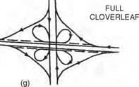
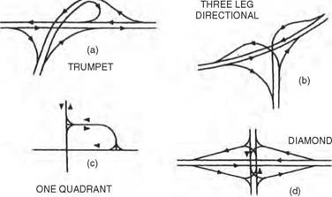
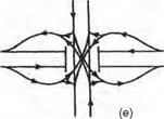
FIGURE 2.40 Common types of interchanges. (a) Trumpet. (b) Three-leg directional. (c) One quadrant. (d) Diamond. (e) Single-point urban. (f) Partial cloverleaf. (g) Full cloverleaf. (h) All directional four leg. (From A Policy on Geometric Design of Highways and Streets, American Association of State Highway Officials, 2004, with permission)


INTERCHANGE RAMP DESIGNINTERCHANGE RAMP DESIGN

TABLE 2.28 Guide for Selecting Ramp Design Speed

Mainline design speed, mi/h

30

35

40

45

50

55

60

65

70

Ramp design speed, upper range, mi/h

25

30

35

40

45

45

50

55

60

Ramp design speed, middle range, mi/h

20

25

30

30

35

35

40

45

50

Ramp design speed, lower range, mi/h

15

15

20

20

25

25

30

30

35

Mainline design speed, km/h

48

56

64

72

80

88

97

105

113

Ramp design speed, upper range, km/h

40

48

56

64

72

72

80

88

97

Ramp design speed, middle range, km/h

32

40

48

48

56

56

64

72

80

Ramp design speed, lower range, km/h

24

24

32

32

40

40

48

48

56

Source: Location and Design Manual, Vol. 1, Roadway Design, Ohio Department of Transportation, with

permission.

• The terminal conditions at each end

• The type of ramp (diamond, loop, or directional)

Diamond ramps normally have a high-speed condition at one end and an at-grade intersection with either a stop or a slow turn condition at the other. Upper – to middle – range design speeds in Table 2.28 are normal near the high-speed facility. Middle – to lower-range design speeds are usually used closer to the at-grade intersection. Loop ramps may have a high-speed condition at one end and either a slow – or a high-speed condition at the other. Loop ramps, because of their relatively short radius, usually have lower-range design speeds in the middle – and slow-speed end of the ramp, and upper – to middle-range design speeds nearer the high-speed terminal(s). Directional ramps generally have high-speed conditions at both ends. They are normally designed using an upper – range design speed, and the absolute minimum design speed should be from the middle range.

Interchanges

An interchange is defined as a system of interconnecting roadways in conjunction with one or more grade separations that provides for the movement of traffic between two or more roadways or highways on different levels. Interchanges are utilized on freeways and expressways, where access control is important. They are used on other types of facilities only where crossing and turning traffic cannot be accommodated by a normal at-grade intersection.

Interchange Spacing. Interchanges should be located close enough together to properly discharge and receive traffic from other highways or streets, and far enough apart to permit the free flow and safety of traffic on the main facility. In general, more frequent interchange spacing is permitted in urbanized areas. Minimum spacing is determined by weaving requirements, ability to sign, lengths of speed change lanes, and capacity of the main facility. Interchanges within urban areas should be spaced not closer than an average of 2 mi (3.2 km), in suburban sections an average of not closer than 4 mi (6.4 km), and in rural sections an average of not closer than 8 mi (12.9 km). In consid­eration of the varying nature of the highway, street, or road systems with which the freeway or expressway must connect, the spacings between individual adjacent inter­changes may vary considerably. In urban areas, the minimum distance between adjacent interchanges should not be less than 1 mi (1.6 km), and in rural areas not less than 2 mi (3.2 km).

Interchange Type. The most commonly used types of interchanges where two routes cross each other are the diamond, cloverleaf, and directional interchanges. When one route ends at an interchange with another route, a trumpet or three-leg directional interchange can be used. Figure 2.40 shows schematic examples of the various types of interchanges. The trumpet interchange (a) has one loop ramp in its design, which is a lower-speed ramp. The three-leg directional interchange (b) incorporates all high­speed ramps in its design. The “one quadrant” interchange (c) has a two-way ramp with at-grade intersections, all in one quadrant of the interchange. This is used primar­ily in urban areas where the routes are both two-way roadways. Typically, this is uti­lized as a first stage in a developing area. Right of way in one or more other quadrants is purchased to allow for future expansion. The diamond interchange (d) is the most common type where a major facility intersects a minor facility. The capacity is limited by the at-grade intersections at the minor crossroad. The single-point urban inter­change (SPUI) shown in (e) can be used when the minor road traffic volume increases and the diamond operation begins to bog down or fail. It allows the use of a single intersection and usually operates on a three-phase traffic signal. Opposing left turns from either the ramps or the side road do not cross paths and therefore can run in the same phase. The third phase is the through traffic on the side road. The partial clover – leaf interchange (f) can be designed to allow some free-flow right turns from the minor road or at least eliminate the need for left turns from the minor road. Signals are usually required to allow access for left-turning vehicles from the ramps onto the minor road. The full cloverleaf interchange (g) eliminates the need for at-grade signalized intersec­tions by providing continuous-flow movements for all traffic. This is used when two major freeways or freeway-style roadways intersect. Under high volumes of traffic, the short weaving distance between the interior ramp terminals creates congestion problems. The use of collector-distributor roads can alleviate some of this problem by separating the through traffic from the entering/exiting traffic. The all-directional four-leg interchange (h) is the most efficient in terms of handling traffic, but is also usually the most expensive. It requires the most right of way and the incorporation of additional bridge structures to accommodate four levels of traffic.

Two-Way Left Turn Lanes

A two-way left turn lane may be considered a special type of “intersection” design, since its purpose is to provide a separate lane for traffic in both opposing lanes to slow down and turn out of the traffic stream in front of opposing traffic. Rather than concentrate the left turners at a single crossroad intersection, the two-way left turn lane spreads out the turning movements over a continuous stretch of roadway. Mid-block left turns are often a serious problem in urban and suburban areas. They can be a safety problem due to angle accidents with opposing traffic as well as rear-end accidents with traffic in the same direction. Mid­block left turns also restrict capacity. Two-way left turn lanes (TWLTLs) have proven to be a safe and cost-effective solution to this problem. TWLTLs should be considered whenever actual or potential mid-block conflicts occur. This is particularly true when accident data indicate a history of mid-block left turn-related accidents. Closely spaced driveways, strip commercial development, and multiple-unit residential land use along the corridor are other indicators of the possible need for a TWLTL. Some guidelines that may be used to justify the use of TWLTLs are listed below:

• 10,000 to 20,000 vehicles per day for four-lane highways

• 5000 to 12,000 vehicles per day for two-lane highways

• 70 mid-block turns per 1000 ft (305 m) during peak hour

• Left turn peak hour volume 20 percent or more of total volume

• Minimum reasonable length of 1000 ft (305 m) or two blocks

Widths for TWLTLs are preferably the same as through lane widths. Lane widths may be reduced to as little as 10 ft (3.0 m) in restricted areas. Care should be taken not to make a TWLTL wider than 14 ft (4.3 m), since this may encourage shared side-by-side use of the lane.