Category HIGHWAY ENGINEERING HANDBOOK

Supports for Utility Poles

Utility supports represent a serious hazard that accounts for about 10 percent of all fixed-object fatal crashes. Elimination, relocation, and burying the lines are preferred options. Increased spacings or multiple use may reduce the number of poles. A breakaway device has been tested and may be considered for vulnerable locations. A breakaway device for utility pole guy wires has also been developed. As with other obstacles, shielding is also an option.

6.3.1 Trees

Collisions of single vehicles with trees account for nearly 25 percent of fixed-object fatal crashes and result in about 3000 deaths each year. Most of these are along county and township roads, which tend to have narrow recovery zones. Certainly, trees should not be planted in the clear zone for new construction, and mowing should discourage growth of seedlings. For existing situations, the hazard should be evaluated. Generally, a single tree with an expected mature size over 4 in (100 mm) is considered a fixed object. For small trees close together, calculate an equivalent diameter based on the combined cross-section area. Large trees should be removed where possible. Warning signs and roadway delineators can be used to indicate where extra caution is advised. Pavement markings and shoulder rumble strips can be helpful. Roadside barriers should generally be used only where the severity of striking the tree is greater than that of striking the barrier.

Supports for Traffic Signals and Service Devices

Supports for traffic signals are not usually of the breakaway type, because of the potential consequences of the loss of the signal at an intersection. Supports in the clear

Supports for Traffic Signals and Service Devices

Подпись: FIGURE 6.11 Breakaway bases for large overhead signs may provide for (a) unidirectional or (b) multidirectional impacts. (From Roadside Design Guide, AASHTO, Washington, D.C., 1996, with permission)

zone should be shielded. Call boxes can often be located behind existing barriers, but a breakaway support is an option. The call box should be securely attached to its support to prevent windshield penetration if dislodged. At highway-railroad crossings, highway and railroad officials should cooperate in deciding on the types of warning devices needed, such as crossbucks, flashing lights, or gates. If the support for the device is located in the clear zone, consider shielding it with a crash cushion. There is seldom room for a longitudinal barrier. Fire hydrants have not been tested to current criteria, but at least one breakaway design is available that includes immediate water shutoff after impact. Mailbox supports should be embedded no more than 24 in (600 mm) in the ground and not set in concrete, the mailboxes should be attached to the supports so that they will not separate after impact, and multiple mailboxes should be spaced apart by a distance of three-fourths of their height.

Luminaire Supports

Breakaway supports for luminaires are usually a cast-aluminum transformer-type fran­gible base, a slip base, or frangible couplers. These devices have been developed to activate when loaded in shear by impacts at a bumper height of about 20 in (500 mm). If the supports are located so that they may be impacted at a greater height, the perfor­mance may not be as intended. Thus, foreslopes between the roadway and the support should be limited to 1:6 or flatter. The mast arm of a falling support will usually rotate away from the roadway. However, the danger of falling poles striking pedestrians, bicyclists, and other motorists should be considered.

Breakaway supports are suitable for poles that do not exceed 60 ft (18.5 m) in height and 1000 lb (450 kg). Foundations must be designed for the surrounding soils to prevent the foundation from pushing through the soil. From a roadside safety perspec­tive, a preferred method for lighting major intersections is to use high-mast lighting, because fewer supports are required and they can be located farther from the roadway. Supports located in the clear zone should be protected with a suitable traffic barrier.

Sign Supports

Roadway signs include overhead signs, large roadside signs (area over 50 ft2 or 5 m2), and small roadside signs.

Overhead signs include sign bridges and cantilevered signs. Their supports are generally too large to adapt to a breakaway design. When possible, install overhead signs on existing bridges or other structures. Otherwise, supports within the clear zone should be shielded with a traffic barrier.

Large roadside signs typically have two or more supports, each of which is of the break­away type. Figures 6.9 and 6.10 show the loading conditions and the breakaway features.

Sign Supports

Note the hinge joint with fuse plate just below the sign and the breakaway base (shear

plate). The supports must resist ice and wind loads and also meet the following criteria:

• The hinge must be at least 7 ft (2.1 m) above ground to prevent windshield penetration.

• A single post 7 ft (2.1 m) or more from another post should have a mass less than 45 lb/ft (65 kg/m); total mass below the hinge but above the shear plate should not exceed 600 lb (270 kg). Two posts spaced less than 7 ft (2.1 m) apart should have a mass less than 18 lb/ft (27 kg/m).

Sign Supports Sign Supports
Sign Supports

Supplementary signs should generally not be placed below the hinges.

FIGURE 6.10 Impact performance of large roadside sign. (From Roadside Design Guide, AASHTO, Washington, D. C., 2002 and 2006, with permission)

Breakaway mechanisms for large sign supports may be either a fracture or a slip – base type. The fracture type includes couplers that fracture, or in the case of wood posts, simply posts with reduced cross-sections. Slip-base-type mechanisms activate when two parallel plates slide apart as bolts are pushed out under impact. As shown in Fig. 6.11, the designs may be of the unidirectional or multidirectional type. The upper hinge design includes a saw cut through the front flange and web of the plate, and a fuse plate on the front flange (impact side). The fuse plate has slotted bolt holes, and the bolts must be torqued to specified values for proper functioning. Alternatively, the fuse plate may have a line of open holes at the cut line, with the plate designed to rupture at the required load, negating the need for the specific values of bolt torque. Even with the breakaway design feature, it is good practice to locate large signs outside the clear zone where feasible.

Small roadside signs may be driven directly into the soil, set in drilled earth holes, or mounted on a base. U-shaped steel posts driven into the ground can generally bend and yield at the base without special devices. Splicing the posts is not usually recom­mended, because performance is not predictable. Wood posts set in drilled holes can fracture at the base, as well as steel pipes connected to anchors driven into the ground. Also, small sign supports may be mounted on fracture bases or slip bases of the unidi­rectional or multidirectional type. A typical unidirectional design uses a four-bolt slot­ted slip base, inclined in the direction of traffic by 10° to 20°. This angle allows the sign to move up so the impacting vehicle can pass underneath. A hinge in the top of the post is not needed. Multidirectional bases are usually triangular and release when struck in any direction. They are often used in medians and at ends of ramps and similar locations. Because torque requirements for slip base bolts are low, wind vibrations have caused supports to “walk” from the slots under wind vibrations, but this can be prevented by using a sheet metal keeper plate. Overtorquing must be prevented, because this causes high friction between the slip base elements and prevents the support from releasing as intended.

SIGN AND LUMINAIRE SUPPORTS AND SIMILAR FEATURES

Approximately 15 percent of all fixed-object fatalities involve sign and luminaire supports or utility poles. The options available to the highway engineer to improve on this record
are similar to those presented earlier: remove or redesign, relocate, use a breakaway device, shield, or delineate. Although it is desirable to have an unobstructed roadside, it is not always possible to relocate appurtenances such as signing and lighting supports, because they must remain near the roadway to fulfill their intended purpose. Thus, emphasis is given to the use of breakaway hardware—selection of the most appropriate device and installing it to ensure acceptable performance. (See Chap. 7.) Supports should be designed in accordance with AASHTO’s Standard Specification for Structural Supports for Highway Signs, Luminaires, and Traffic Signals.

Breakaway supports include all types of sign, luminaire, and traffic signal supports designed to yield when hit by a vehicle. Typical release mechanisms include slip planes, plastic hinges, and fracture elements. Criteria for breakaway supports are given in National Cooperative Highway Research Program (NCHRP) Report 350, Recommended Procedures for the Safety Performance Evaluation of Highway Features. The criteria require that a breakaway support fail in a predictable manner when struck head on by a 1800-lb (820-kg) vehicle, or its equivalent, at speeds of 20 and 60 mi/h (35 and 100 km/h). It is desirable to limit the occupant impact velocity to 10 ft/s (3.0 m/s), but values as high as 16 ft/s (5.0 m/s) are acceptable. Also, the maximum stub height is set at 4 in (100 mm) to avoid snagging the undercarriage after impact. The crash vehicle must remain upright with no significant deformation or intrusion of the passenger compartment.

Full-scale crash tests, tests with bogie vehicles (reusable, adjustable surrogate vehicle), and tests with pendulums (having special nose sections to model vehicles) are used for acceptance. Pendulum tests are the least expensive, but are used mostly for luminaire support hardware and are mainly limited to 20 mi/h (35 km/h). NCHRP Report 350 dis­cusses acceptance testing. Tests are run in a standard soil, but weak soil should be used in addition for any feature whose impact performance is sensitive to soil-structure interaction.

Many general practices are similar to those previously discussed. Supports should not be placed in drainage ditches, because vehicles may be channeled into the obstacle and freezing might interfere with proper functioning of the breakaway device. Also, breakaway supports must not be located near ditches or on steep slopes where a vehicle is likely to be partially airborne at impact, because breakaway devices may bind and not function properly when hit in this manner. They have been developed to be struck about 20 in (500 mm) above the ground.

Locate supports where they are least likely to be hit, such as behind roadway barriers (beyond design deflections of the barriers) or on existing structures. In general, only when the use of breakaway supports is not feasible should a traffic barrier or crash cushion be used for shielding. Generally, breakaway supports should be used unless an engineering study indicates otherwise. Concern for pedestrians being struck by falling supports after a crash has led to the use of fixed supports in some urban areas such as near bus shelters or where there are extensive pedestrian concentrations.

Drainage Features

The drainage system should be designed, constructed, and maintained with considera­tions for both the hydraulic function and roadside safety. (See Chap. 5.) In addition to channels, elements of the system include curbs, cross-drainage (transverse) structures (pipes and culverts), parallel drainage structures, and drop inlets. The following three options, listed in order of preference, are applicable to each:

• Eliminate nonessential drainage structures.

• Design or modify drainage structures so they are traversable or present minimal hazard to errant vehicles.

• If relocation or redesign is impractical, shield with a traffic barrier if in a vulnerable location.

Curbs may be classified as vertical or sloping types. Vertical curbs, defined as those with vertical or nearly vertical faces, 6 in (150 mm) or more in height, discourage

Drainage Features

a1:b1

motorists from leaving the highway. Sloping curbs have lower heights with sloping faces that can be easily traversed. Heights of 4 in (100 mm) or less are preferred for the latter to avoid dragging the underside of vehicles. Neither type of curb is desirable on high-speed highways, because either may cause overturning, particularly if the vehicle is spinning or slipping. In urban areas, a minimum horizontal clearance of 1.5 ft (0.5 m) beyond the face of the curb should be provided to obstacles. On high-speed roadways, curbs should not be used in front of traffic barriers, because unpredictable postimpact trajectories can result. If a curb must be used, locate it flush with the face of the railing

Drainage Features

or behind it. Curb-barrier combinations for bridge railings should be crash-tested unless data are available.

Cross-drainage structures carry streams or drainage water transversely underneath the embankment. They may range in size from 18 in (450 mm) to 10 ft (3 m) or more, may be constructed of concrete, metal, or plastic (in some sizes), and may be furnished as round pipe, elliptical shapes, or boxes. Typically, inlets and outlets of larger structures have con­crete headwalls and wingwalls, and those of smaller structures are beveled to match the slope. Pipe may also be furnished with square-cut ends. These designs may result in a
fixed object protruding above an embankment or an opening into which a vehicle can drop, causing an abrupt stop. Options available to minimize such obstacles include

• A traversable design

• Extension of the structure so it is less likely to be hit

• Shielding the structure

• Delineating the structure (when other measures are not feasible)

Traversable design. If a slope is generally traversable, the preferred treatment is to extend or shorten the structure and match the inlet or outlet shape to the embank­ment slope. Further treatment should not be required for small culverts, defined as a single pipe with a diameter of 36 in (900 mm) or less or multiple pipes with diameters of 30 in (750 mm) or less each. Single structures and end treatments wider than 3 ft (1 m) can be made traversable for passenger-size vehicles by using bar grates or pipes to reduce the clear opening width. To maintain hydraulic efficiency, it may be necessary to apply bar grates to flared wingwalls, flared end sections, or culvert extensions larger than the main barrel. Crash tests have shown that automobiles can cross grated culvert end sections on slopes as steep as 1:3, at speeds from 20 to 60 mi/h (30 to 100 km/h), when steel pipe on 30-in (750-mm) centers is used. This spacing does not significantly affect flow unless debris accumulates and causes clogging.

Design recommendations for safety treatment of culvert ends are summarized in Fig. 6.7. Where debris accumulation is not a concern and mowing operations are fre­quent, smaller openings may be tolerated and grates similar to those for drop inlets may be appropriate. In median areas, consider making culverts continuous and adding a median drainage inlet.

Extension of structure. For larger-sized drainage structures with inlets or outlets that cannot be readily made traversable, the structure can be extended so the obstacle is located at the edge or beyond the clear zone. This reduces but does not eliminate the possibility of hitting the pipe end. If the culvert headwall remains the only fixed object at the edge of the zone, simply extending the opening to the edge may not be the best solution. However, if there are numerous obstacles along the edge of the zone on the section under consideration, extension of the pipe might be an appropriate solution.

Span length, ft (m)

Inside diameter, in (mm)

3 (75)

Up to 12 (Up to 3.65)

3.5 (87)

12 to 16 (3.65 to 4.90)

4 (100)

16 to 20 (4.90 to 6.10)

3 (75)

20 (6.10 or less with center support)

Drainage Features

Each 30 in max. (750 mm)

Drainage Features
Section A-A

FIGURE 6.8 Safety treatment for drainage inlet or outlet. (From Roadside Design Guide, AASHTO, Washington, D. C., 2002 and 2006, with permission)

Shielding of structure. An appropriate traffic barrier should be considered for shielding a drainage structure that cannot be reasonably made traversable or extended outside the clear zone. Because the barrier will be closer to the roadway and longer than the obstacle, it is more likely to be hit. However, if properly designed, constructed, and maintained, the barrier should provide an increased level of safety.

Parallel drainage structures are those that are oriented parallel to the traffic flow to carry water under driveways, entrances, ramps, side roads, and median crossovers. Such structures may represent a significant hazard if they can be struck head on by an errant vehicle. Options for safety treatment are similar to those for cross-drainage structures. If entrances are closely spaced, consider converting the open channel into a closed storm drain, backfilling areas between entrances, and eliminating multiple obstacles. Research has shown that, for parallel drainage structures, wheel snagging can be significantly reduced with pipe grates oriented perpendicular to the traffic direction and having a spacing of 24 in (600 mm) or less. Single pipes of 24 in (600 mm) diameter or less generally do not require a grate, but multiple small pipes may require one. Figure 6.8 illustrates a design for the ends of a parallel culvert. In situations such as intersecting ramps, consider relocating the culvert farther back from the main road, out of the clear zone.

Drop inlets include on-roadway and off-roadway structures. On-roadway inlets, which are located along the shoulder to intercept surface runoff, include curb opening inlets, grated inlets, and slotted drains. If installed flush with the pavement, they do not cause a significant safety problem. Off-roadway drop inlets are used in medians of divided roadways or in roadside ditches. The hazard can be minimized by making the inlets flush with the drainage surface. Safety treatment should be such as to prevent a vehicle from dropping into the inlet, snagging, and losing control.

Roadside Geometry

Except for flat roadsides, a motorist leaving the roadway may encounter a foreslope (negative grade such as on an embankment), a backslope (positive grade such as in a cut section), a transverse slope (such as caused by an intersecting side road), or a drainage channel (change from negative to positive grade).

Foreslopes parallel to the traffic flow may be categorized as recoverable, nonrecov­erable, or critical. Recoverable slopes are 1:4 (vertical to horizontal) or flatter, and the

Подпись: CLEAR ZONE WIDTH = 6m
Подпись: ANSWER:
Подпись: CD P

Подпись: THROUGH TRAVEL'

Roadside Geometry Подпись: лоокщЪ- Oesi9n Spe
Roadside Geometry
Подпись: 750- 1500 DESIGN A.D
Подпись: UNDER 750 DES GN A

Roadside GeometryCLEAR-ZONE DISTANCE (m)

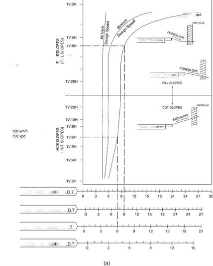
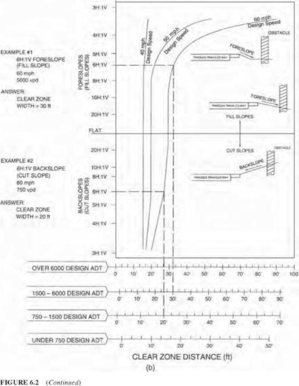
FIGURE 6.2 Clear zone distance curves. (a) SI units; (b) U. S. Customary units. (From Roadside Design Guide, AASHTO, Washington, D. C., 2002 and 2006, with permission) clear zone distance from Fig. 6.2 applies directly. Fixed obstacles such as culvert head – walls should not extend above the embankment in this zone. Nonrecoverable slopes, generally between 1:4 and 1:3, are traversable, but most motorists will reach the bottom of the slope and not be able to stop or return to the roadway easily. Fixed obstacles should not be constructed along such slopes, and a clear runout area at the bottom of the slope is desirable. Critical slopes, generally steeper than 1:3, are those on which a vehicle is likely to overturn. A barrier might be warranted in such cases. Figure 6.3 dis­cusses alternatives that might be considered on critical parallel foreslopes.

Roadside Geometry

Many highway agencies construct so-called barn roof sections in embankment con­ditions as illustrated in Fig. 6.4. A relatively flat slope is provided adjacent to the roadway, followed by a steeper slope and a clear runout area at the bottom. This is more economical than a continuous flat slope and apparently safer than a continuous steeper slope from the edge of the shoulder. In applying the clear zone concept, side slopes ranging from flat to 1:4 may be averaged to produce a composite clear zone distance. Slopes that change from negative to positive should be treated as channel sections. Changes in slope and toes of slopes should generally be rounded to keep vehicles in contact with the ground and enhance traversability.

EXAMPLE I

Design ADT: 12,000

Design Speed: 70 mph (110 km/h)

Keeonirnended dear-zone distance Гог I V:6II forcslopc: 30 to 34 ft (9 to 10.5 im

Roadside Geometry

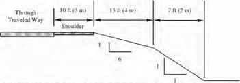
Discussion: Since the critical foreslopc is only 23 ft (7 no from the through traveled way. instead of die suggested 30 to 34 ft (9 lo 10.5 in), и should be flattened if practical or considered for shielding. However, if this is an isolated obstacle and the roadway has no significant crash history, it may be appropriate to do little more than delineate the drop-off in lieu of foreslope flattening or shielding

Although a "weighted" average of the foreslopcs may be used, a simple average of the clcar-zone distances for each foreslope is accurate enough if the variable foreslopcs arc approximately the same width II one foreslope is significantly wider, the clcar-zone computation based on that foreslope alone may be used.

EXAMPLE 2

Design ADT: 350

Design Speed: 40 mph (60 km/h)

Recommended dear-zone distance for I V:5II foreslopc: 7 to 10 ft <2 to 3 rni

Roadside Geometry

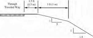
Discussion: The available 4.5 ft 11.5 in) is 2.5 to 5.5 ft (0.5 lo 1.5 ml less than the recommended recovery area. If much of this roadway has a similar cro&s-section and no significant run-off-the-roed crash history, neither foreslopc flattening nor a traffic barrier would be recommended On the oilier hand, even if the I V;5H foreslopc were 10 ft (3 m) w-idc and (he clcar-zone requirement were met. u traffic barrier might be appropriate it (his locution had noticeably less recovery area than the rest of the roadway and the embankment was unusually high.

FIGURE 6.3 Examples of application of clear zone concept to critical parallel foreslopes on (Example 1) high-volume and (Example 2) low-volume highways. (From Roadside Design Guide, AASHTO, Washington, D. C., 2002 and 2006, with permission.)

On backslopes, traversability depends on relative smoothness and the presence of fixed obstacles. If traversable (1:3 slope or flatter) and obstacle free, it may be acceptable. Conversely, a steep rough-sided rock cut (one that will cause excessive vehicle snagging) should be shielded unless it is outside the clear zone.

Transverse slopes may be created by median crossovers, intersecting side roads, or driveways. These generally create a more serious condition than parallel slopes because they can be struck head on by errant vehicles. To minimize the effect, slopes of 1:10

Clear zone distance

Clear runout area required

Through traveled way

Shoulder

Recoverable slope

Nonrecovera

slope

ble

Clear runout area

1:4 or flatter slope (1:6 or flatter desirable)

Slopes between 1:3 and 1:4

1:6 or flatter slope desirable

FIGURE 6.4 Example of “barn roof’ section for parallel foreslope design; recoverable slope is followed by a nonrecoverable slope. (From Roadside Design Guide, AASHTO, Washington, D. C., 2002 and 2006, with permission)

or flatter are desirable where practical. Steeper slopes may be suitable for low-speed facilities. Drainage pipes should be located as far from the roadway as practical. Also, where a vehicle could be led into the culvert inlet or outlet by a drainage channel, consid­eration should be given to special inlet or outlet treatment, as subsequently discussed.

Drainage channels are open flow areas generally paralleling the highway embank­ment within the right-of-way. They serve to collect surface runoff that drains from the highway and convey it to outlets. In addition to providing drainage functions, channels should be proportioned so that they are traversable. The shaded areas in Figs. 6.5 and 6.6 show preferred (traversable) slopes for the sides of channels. Where practical, channel sec­tions outside the shaded areas may be reshaped, converted to a closed system (culvert), or shielded by a barrier. For all channels, roadside hardware (for example, sign supports) should not be located in or near channel bottoms or slopes because vehicles leaving the roadway may be funneled along the channel and impact the obstacle. Breakaway hard­ware may not function properly if impacted by airborne or sideways-sliding vehicles.

APPLICATION OF CLEAR ZONE CONCEPT TO SLOPE AND DRAINAGE DESIGN

The clear roadside concept has a direct and obvious application to the selection of slopes and design of drainage features such as ditches, curbs, culverts, and drop inlets. A traversable, unobstructed roadside zone should extend beyond the edge of the driving lane for an appropriate distance so that the motorist can generally stop or slow the vehicle and return to the roadway safely.

The width of the zone depends on the traffic volume, the design speed, and the road­side slope. Vehicles on high-volume, high-speed routes obviously require more room to recover than those on less congested routes. A suggested guide for determining the width of the clear zone is presented in Fig. 6.2. The clear zone distance (width) is given in terms of the range of design average daily traffic (ADT) or vehicles per day (VPD), the design speed, and the roadside slope. Enter the chart from the left with the slope, intersect the appropriate design speed curve, and project down to the appropriate scale at the bottom to read the suggested width. The width should be used as a guide and may be adjusted for site-specific conditions and practicality. The AASHTO guide gives modifi­cation factors (1.1 to 1.5) that can be applied to increase the clear distance on horizontal curves where accident histories or site investigations show a need. Increased superelevation may be another option, depending on climatic conditions.

CONCEPTS AND BENEFITS OF ROADSIDE SAFETY

The roadside is defined as that area beyond the traveled way and shoulder. Thus, road­side safety is concerned with treatments that minimize the likelihood of serious injuries when a vehicle runs off the roadway.

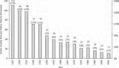
Roadside safety design has received particular emphasis since the 1960s. The increased awareness of its importance and the development of improved safety concepts and devices have contributed significantly to improved safety. As shown in Fig. 6.1, the traffic fatality rate expressed in terms of driven distance has declined to one-third of that in the mid-1960s. Many factors have contributed to the declining rate, including safer vehicles (occupant restraints, door beams, crash energy management, etc.) and improved roadways (intersection geometry, superelevation, grade separation, etc.). However, road­side improvements have played a key role in reducing fatalities.

Cost-effective roadside safety concepts and features must be incorporated in both new construction and in rehabilitation projects.

CONCEPTS AND BENEFITS OF ROADSIDE SAFETY

FIGURE 6.1 Traffic fatality rate continues to decline. (From Roadside Design Guide, AASHTO, Washington, D. C., 2002 and 2006, with permission)

Roadside safety must be addressed because a significant number of vehicles inevitably leave the roadway. There are a variety of reasons for this, such as:

• Driver fatigue or inattention

• Excessive speed

• Driving under the influence of alcohol or drugs

• Collision avoidance

• Roadway condition (ice, snow, rain)

• Vehicle component failure

• Poor visibility

To reduce the severity of accidents involving these errant vehicles, the roadside should have relatively flat slopes and be free of fixed objects. What is known as the forgiving roadside concept has generally become an integral part of highway design criteria. Obstacles most often responsible for roadside fatalities include

• Trees and shrubs

• Utility poles

• Culverts and ditches

• Curbs and walls

• Sign and luminaire supports

• Bridge piers and abutments

Design options often employed for addressing a roadside obstacle include

• Removing the obstacle

• Redesigning the obstacle so it can be safely traversed

• Relocating the obstacle

• Using breakaway devices

• Shielding the obstacle with a barrier or crash cushion

• Delineating the obstacle

As with virtually all highway construction, funds for safety improvements are limited, and thus, emphasis must be given to improvements that are cost-effective and offer the greatest opportunities for safety enhancement. Some features such as breakaway supports and bridge railings are routinely included on the basis of a subjective analysis of obvious benefits. In other cases, where alternatives exist, benefit-cost and value engineering studies should be used to aid in rational decisions. Benefits include expected reduction in accident costs, including the cost of personal injuries and property damage, based on the expected reduction in number and severity of accidents associated with the improvement. Costs include direct construction cost and maintenance. The study must be based on a specific project life so that benefits and costs can be annualized. This involves the application of discount rates and life-cycle costs as discussed in Chap. 10. The computer program Roadside Safety Analysis Program (RSAP) is available to aid in the selection process. Contact the Transportation Research Board, NCHRP, 2101 Constitution Ave. NW, Washington, D. C. 20418.

SAFETY SYSTEMS

Roger L. Brockenbrough, PE.

President

R. L. Brockenbrough & Associates, Inc.
Pittsburgh, Pennsylvania

One of the most important and most challenging aspects of highway engineering is designing to enhance life safety. This chapter focuses on roadside safety, which encompasses the safety of vehicles that leave the roadway and shoulder.

This material is based largely on the publication of the American Association of State Highway and Transportation Officials (AASHTO), Roadside Design Guide (2002, 2006), which was developed by the AASHTO Subcommittee on Design, Task Force for Roadside Safety, currently under the chairmanship of Keith A. Cota. Made up of about 20 highway engineers with diverse experience, the task force maintains and updates a synthesis of current information and operating practices to serve as a comprehensive guide to individuals and agencies in developing standards and policies. Their contribution to promoting highway safety is gratefully acknowledged.