Category HIGHWAY ENGINEERING HANDBOOK

Terrain Effects

Ideally, at the moment of impact, a vehicle should have all wheels on the ground and the suspension system in a neutral state. Thus, terrain conditions between the traveled way and the barrier are very important. For example, curbs should be avoided and should be no higher than 4 in (100 mm) if used. In many cases, they can be located behind the barrier. Barriers are usually tested on level terrain. If installed on slopes steeper than 1:10, vehicles may go over standard barriers or impact them too low, and thus not perform as anticipated.

6.7.2 Flare Rate

Roadside barriers must be flared (must have variable offset from the traveled way) to locate the barrier terminal back from the roadway and thus to minimize drivers’ reaction to a perceived hazard near the road when approaching a bridge parapet or railing, for example. However, the greater the flare rate, the greater the potential impact angle and the severity of an accident if the barrier is hit. Also, the chance that a vehicle would be redirected across the roadway increases. Maximum flare rates depend on design speed, barrier type, and location relative to the shy line as shown in Table 6.4. Adjustment to a flatter rate is sometimes made to avoid extensive grading.

Flare rate for
barrier beyond shy line

70 (110)

30:1

20:1

15:1

60 (100)

26:1

18:1

14:1

55 (90)

24:1

16:1

12:1

50 (80)

21:1

14:1

11:1

45 (70)

18:1

12:1

10:1

40 (60)

16:1

10:1

8:1

30 (50)

13:1

8:1

7:1

Design speed, Flare rate for barrier Rigid Semirigid

mi/h (km/h) inside shy line systems systems

Source: From Roadside Design Guide, AASHTO, Washington, D. C.,

2002 and 2006, with permission.

PLACEMENT OF ROADSIDE BARRIERS

Factors to consider in specifying the exact layout of a barrier at a given location include lateral offset from the edge of the traveled way, terrain effects, flare rate, and length of need. (See also Art. 6.10.)

6.7.1 Lateral Offset

Roadside barriers should generally be placed as far from the traveled way as condi­tions permit, to allow motorists the best chance of regaining control and to provide better sight distance. It is desirable to maintain a uniform clearance between traffic and roadside features such as bridge railings, retaining walls, and roadside barriers. The distance beyond which a roadside object will not be perceived as an obstacle and cause a motorist to reduce speed or change position is known as the shy line offset. According to the AASHTO Roadside Guide, this distance varies with design speed as follows:

Design speed Shy line offset

mi/h

km/h

ft

m

80

130

12.1

3.7

75

120

10.5

3.2

70

110

9.2

2.8

60

100

7.9

2.4

55

90

7.2

2.2

50

80

6.6

2.0

45

70

5.6

1.7

40

60

4.6

1.4

30

50

3.6

1.1

Place the barrier beyond the shy line offset when possible, particularly for short, isolated installations. Uniform alignment reduces the possibility of snagging. Proper transition where a barrier connects to other features is essential. Short gaps between barriers should be avoided; make the barriers continuous instead. The barrier-to-obstacle dis­tance must be greater than the expected dynamic deflection of the barrier. Where shielding an embankment, the distance from the barrier to the beginning of the down slope should generally be at least 2 ft (0.6 m), but this may vary with local conditions for soil support of the post.

SELECTION OF ROADSIDE BARRIERS

In most cases, the selection of a roadside barrier should be made on the basis of the system that will provide the required degree of shielding at the lowest cost. The lowest cost should be based on a life-cycle cost analysis, considering initial and maintenance costs

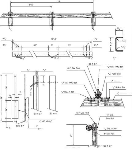
Подпись: AASHTO designation: Post Type: Beam Type: Nominal Barrier Height:

SELECTION OF ROADSIDE BARRIERS Подпись: Й ;r 7" 3 4 88" 4"3 7" 'I —r - End of timber rail 1’/; 1V dia. holes for 3/8" dia. holes (typ.) 1 I lag screws (typ.) 8 Чч . - . ' : 5 : -тп 14" Steel plate " %" thickness - 8 spaces at 11" TT 14" STEEL RAIL (typ.)

None

10 in x 12 in x 7 in rough-sawn timber 6 in x 10 in timber with steel plate backing 27 in

FIGURE 6.20 Steel-backed wood-rail roadside barrier. Conversions: 1 in = 25.4 mm, 1 ft = 0.305 m. (From Roadside Design Guide, AASHTO, Washington, D. C., 2002 and 2006, with permission) and project life. Factors that should be considered in making the selection are summarized in Table 6.3. The most important decision is the performance level required. In general, TL-2 or TL-3 barriers are satisfactory for most locations, but higher-performance barriers (TL-4 or greater) should be considered for locations with poor geometries, high traffic volumes and speeds, and concentrations of heavy truck traffic. The deflection charac­teristics of the barrier must be considered in relation to the available space. Some systems can be modified to decrease deflections by decreasing post spacing or increasing the

SELECTION OF ROADSIDE BARRIERS

Symmetrical

SELECTION OF ROADSIDE BARRIERS


SELECTION OF ROADSIDE BARRIERS

(a) (b)

AASHTO Designation: MBS

The 32-in-high concrete safety shape was initially installed primarily as a median barrier, but has become commonly used as both a bridge railing and a roadside barrier, Most of these barriers use the standard New Jersey shape; any extension in barrier height occurs above the slope break point. Several stales extend the upper stem to serve as a maintenance-free glare screen. The two designs shown above are the extreme heights to which roadside barriers have been constructed— both along ramps with a history of truck accidents.

FIGURE 6.21 Variations of concrete safety shape for roadside barrier in severe applications showing (a) symmetrical form and (b) earth-backed installation. Conversion: 1 in = 25.4 mm. (From Roadside Design Guide, AASHTO, Washington, D. C., 2002 and 2006, with permission)

number of rails. A computer program, Analysis of Roadside Design (NARD), is avail­able for predicting maximum deflections for blocked-out W-beam and thrie-beam systems with different post spacings and single or double rails. On all systems, data on impact performance and maintenance costs should be tabulated and made available to provide better information for the selection of roadside barriers.

Variable offset

Stone masonry facing

Concrete со rewall

Edge of. pavement

6-#5 x 9′-4"

bars (spaced as shown)

AASHTO Designation: None

Подпись:This barrier consists of a reinforced concrete core faced with stone rubble masonry. Designed for use in scenic areas, combine to make it an effective barrier for use on parkways and similar facilities.

Criterion

Comments

Performance capability

Barrier must be structurally able to contain and redirect design vehicle.

Deflection

Expected deflection of barrier should not exceed available room to deflect.

Site conditions

Slope approaching the barrier, and distance from traveled way, may preclude use of some barrier types.

Compatibility

Barrier must be compatible with planned end anchor and capable of transition to other barrier systems (such as bridge railing).

Cost

Maintenance

Standard barrier systems are relatively consistent in cost, but high-performance railing can cost significantly more.

Routine

Few systems require a significant amount of routine maintenance.

Collision

Generally, flexible or semirigid systems require significantly more maintenance after a collision than rigid or high-performance railings.

Materials storage

The fewer different systems used, the fewer inventory items or the less storage space required.

Simplicity

Simpler designs, besides costing less, are more likely to be reconstructed properly by field personnel.

Aesthetics

Occasionally, barrier aesthetics is an important consideration in selection.

Field experience

The performance and maintenance requirements of existing systems should be monitored to identify problems that could be lessened or eliminated by using a different barrier type.

Source: From Roadside Design Guide, AASHTO, Washington, D. C., 2002 and

2006, with permission.

Rigid Systems

The concrete safety shape system (Fig. 6.21), which has a sloping front face, is similar to the concrete median barrier (Art. 6.9.1) but usually has a vertical back face. The reduced cross-section of the roadside barrier version makes it more vulnerable to over­turning, thus requiring more reinforcing steel and/or a more elaborate footing design. The New Jersey shape at a height of 32 in (810 mm) meets TL-4 and at a height of 42 in (1070 mm) meets TL-5. Both the New Jersey profile and the F-shape profile shown in Fig. 6.21 are acceptable. The F-shape reportedly showed better performance in crash tests with 1800-lb (820-kg) cars and 18,000-lb (8000-kg) single-unit trucks. Higher designs have been tested and constructed to redirect heavy vehicles. For example, the

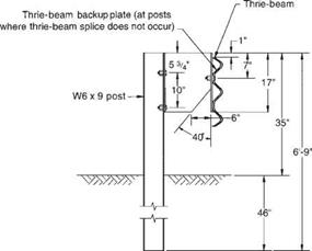
Подпись: AASHTO Designation: Post Type: Offset Block: Post Spacing: Beam Type: Nominal Barrier Height: Maximum Dynamic Deflection:

Rigid Systems

None

W6 x 9 steel or 6 in x 8 in wood M14 x 18 steel 6 ft-3 in

12-gage thrie-beam 34 in

Approximately 3 ft for a 20,000-pound school bus (56 mph, 15° impact angle)

Remarks: Modified thrie-beam was first installed in Rhode Island, Colorado, Nebraska, and Michigan as an experimental barrier. Since that time, it has been reclassified as an operational system, requiring virtually no repair for shallow-angle hits. This barrier can accommodate vehicles ranging in size from 1700-lb subcompacts to a 33,000-lb intercity bus,

FIGURE 6.19 Modified thrie-beam roadside barrier. Conversions: 1 in = 25.4 mm, 1 ft = 0.305 m. (From Roadside Design Guide, AASHTO, Washington, D. C., 2002 and 2006, with permission)

version shown in Fig. 6.21a is 90 in (2290 mm) high; also, it is sloped on both faces. It contains impacting tractor-trailers but has not completely eliminated rollovers. Successfully testing to TL-6 has been reported. The version shown in Fig. 6.21b is 64 in (1630 mm) high. Apparently effective, it is buttressed by an earth berm on the back side and topped with a W-beam barrier. Constant slope and vertical wall barriers have also been successfully tested (Art. 6.9.1).

The stone masonry wall system (Fig. 6.22), with a reinforced concrete core and a facing of stone and mortar, offers another aesthetic alternative for parks and similar applications. This barrier meets TL-3. Alternative systems with precast units are also available.

Semirigid Systems

The box-beam (weak-post) system (Fig. 6.16) achieves its resistance through the com­bined flexural and tensile resistance of the box beam. Posts near the impact point are designed to break or tear away and distribute the impact force to adjacent posts. This system meets TL-3. The system is sensitive to mounting height and irregularities in terrain.

The blocked-out W-beam (strong-post) system (Fig. 6.17) is the most common barrier. The blockout or offset of the rail from the post minimizes vehicle snagging and reduces likelihood that a vehicle would vault over the barrier. The system is classified as TL-2 or TL-3, depending upon the type of blocks. As with all strong-post systems, resistance is developed by a combination of the tensile and flexural resistance of the rail and the flexural and shear strength of the post. Dynamic deflections are less than those of flexible systems. Bolt washers on the posts can be eliminated on this and other strong-post systems; they are not needed for strength, and it is desirable for the rail to break away as the post rotates downward. Strong-post systems tend to remain functional after moderate collisions, so that immediate repairs are not necessary.

The blocked-out thrie-beam (strong-post) system (Fig. 6.18) is similar to the pre­ceding system, but it has a deeper, stiffer, three-corrugation rail. This makes it less prone to damage during impact, allows higher rail mounting, and is better able to contain larger vehicles under some impact conditions. The system is classified as TL-2 or TL-3, depending upon the type of blocks.

The modified thrie-beam system (Fig. 6.19) has a steel blockout with a triangular notch cut from its web. This allows the lower part of the beam and the face of the spacer block to bend in during impact, causes the rail face to remain nearly vertical as the post is bent back, and reduces likelihood that a vehicle would roll over the barrier.

5-3

Подпись:УУАУАУА4

Soil Plate

Typical

AASHTO Designation

Подпись: 6 in x 6 in x 0.19 in steel tube Approximately 5 ft
Подпись: Beam Type:
Подпись: Maximum Dynamic Deflection

Semirigid SystemsPost Type: Post Spacing:

Semirigid Systems

FIGURE 6.17 Blocked-out W-beam (strong-post) roadside barrier. Conversions: 1 in = 25.4 mm, 1 ft = 0.305 m. (From Roadside Design Guide, AASHTO, Washington, D. C., 2002 and 2006, with permission)

Also, bolt washers have been eliminated on the posts, as discussed previously. The modifications have resulted in a TL-4 rating. Repair costs of either thrie-beam system should be considerably less than for other metal barrier systems, because damage tends to be slight in shallow-angle impacts. Also, it is considered easier to install and main­tain than a W-beam system with rub rail.

Semirigid Systems

FIGURE 6.18 Blocked-out thrie-beam (strong-post) roadside barrier. Conversions: 1 in = 25.4 mm, 1 ft = 0.305 m. (From Roadside Design Guide, AASHTO, Washington, D. C., 2002 and 2006, with permission)

The steel-backed timber-rail system (Fig. 6.20) is an aesthetic alternative to conventional systems, often selected for use along park roads. It has been successfully tested to TL-3.

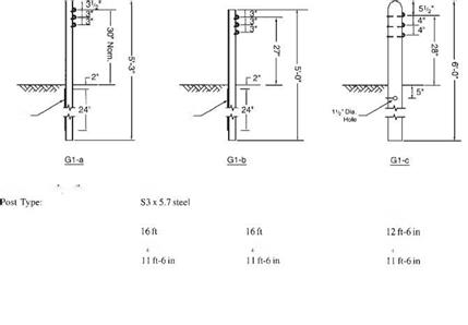
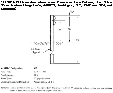
The three-cable system (Fig. 6.13) has been successfully tested to TL-3. It is made up of three steel cables mounted on weak posts. The cable barrier redirects impacting vehicles after the cable deflects and develops tension, with the posts offering little direct resistance. Several states allow a backslope as steep as 1:2 behind the rail. If the barrier is placed on the inside of a curve, additional deflection will occur before tension develops in the cable, and thus it may be desirable to limit the radius. New York installs the barrier having S3 X 5.7 (S75 X 8.5) steel posts for radii of 721.5 ft (220 m) or more with the standard 16-ft (4.9-m) post spacing, and for radii of 442.5 ft (135 m)

TABLE 6.2 Classification of Roadside Barriers and Approved Test Levels

Barrier system Test level

Flexible systems

Three-strand cable (weak-post) TL-3

W-beam (weak-post) TL-2

Modified W-beam (weak-post) TL-3

Ironwood aesthetic barrier TL-3

Semirigid systems

Box-beam (weak-post) TL-3

Blocked-out W-beam (strong-post)

Steel or wood post with wood TL-3

or plastic block

Steel post with steel block TL-2

Blocked-out thrie-beam (strong-post)

Wood or steel post with wood TL-3

or plastic block

Modified thrie-beam (strong-post) TL-4

Merritt Parkway aesthetic guardrail TL-3

Steel-backed timber guardrail TL-3

Rigid systems (concrete and masonry)

New Jersey concrete safety-shape

32 in (810 mm) tall TL-4

42 in (1070 mm) tall TL-5

F-shape barrier

32 in (810 mm) TL-4

42 in (1070 mm) TL-5

Vertical concrete barrier

32 in (810 mm) TL-4

42 in (1070 mm) TL-5

Single-slope barrier

32 in (810 mm) TL-4

42 in (1070 mm) TL-5

Ontario tall-wall median barrier TL-5

Stone masonry wall/precast TL-3

masonry wall

Source: From Roadside Design Guide, AASHTO,

Washington, D. C., 2002 and 2006, with permission.

or more with a 12-ft (3.7-m) post spacing. Advantages of the three-cable barrier include low initial cost, effective vehicle containment and redirection over a wide range of vehicle sizes and installation conditions, low deceleration forces, and func­tionality in snow or sand areas because the open design prevents drifting. Disadvantages include the long lengths that are nonfunctional and must be repaired after an impact, the clear area behind the barrier needed to accommodate the design deflection distance, reduced effectiveness on the inside of curves, and sensitivity to correct height installation and maintenance.

The W-beam (weak-post) system (Fig. 6.14) behaves much like a cable system, but the deflection is much less. Thus, the required clear area behind the barrier is less. The

The three-cable system (Fig. 6.13) has been successfully tested to TL-3. It is made up of three steel cables mounted on weak posts. The cable barrier redirects impacting vehicles after the cable deflects and develops tension, with the posts offering little direct resistance. Several states allow a backslope as steep as 1:2 behind the rail. If the barrier is placed on the inside of a curve, additional deflection will occur before tension develops in the cable, and thus it may be desirable to limit the radius. New York installs the barrier having S3 X 5.7 (S75 X 8.5) steel posts for radii of 721.5 ft (220 m) or more with the standard 16-ft (4.9-m) post spacing, and for radii of 442.5 ft (135 m)

Soil Plate Typical"


Soil Plate Typical


A ASHTO Designation:


Gl-a


The three-cable system (Fig. 6.13) has been successfully tested to TL-3. It is made up of three steel cables mounted on weak posts. The cable barrier redirects impacting vehicles after the cable deflects and develops tension, with the posts offering little direct resistance. Several states allow a backslope as steep as 1:2 behind the rail. If the barrier is placed on the inside of a curve, additional deflection will occur before tension develops in the cable, and thus it may be desirable to limit the radius. New York installs the barrier having S3 X 5.7 (S75 X 8.5) steel posts for radii of 721.5 ft (220 m) or more with the standard 16-ft (4.9-m) post spacing, and for radii of 442.5 ft (135 m)

The three-cable system (Fig. 6.13) has been successfully tested to TL-3. It is made up of three steel cables mounted on weak posts. The cable barrier redirects impacting vehicles after the cable deflects and develops tension, with the posts offering little direct resistance. Several states allow a backslope as steep as 1:2 behind the rail. If the barrier is placed on the inside of a curve, additional deflection will occur before tension develops in the cable, and thus it may be desirable to limit the radius. New York installs the barrier having S3 X 5.7 (S75 X 8.5) steel posts for radii of 721.5 ft (220 m) or more with the standard 16-ft (4.9-m) post spacing, and for radii of 442.5 ft (135 m)

Post Spacing:

Подпись:Подпись: 7 -in-dia. steel cablesBeam Type:

Maximum Dynamic Deflection:

Подпись:
Remarks: For shallow angle impacts, barrier damage is usually limited to several posts, which must be replaced. Cable damage is rare except in severe crashes. A crashworthy end terminal is critical in each of the cable systems, both to provide adequate anchorage to develop full tensile strength in the cable and to minimize vehicle decelera­tions for impacts on either end of an installation.

The three-cable system (Fig. 6.13) has been successfully tested to TL-3. It is made up of three steel cables mounted on weak posts. The cable barrier redirects impacting vehicles after the cable deflects and develops tension, with the posts offering little direct resistance. Several states allow a backslope as steep as 1:2 behind the rail. If the barrier is placed on the inside of a curve, additional deflection will occur before tension develops in the cable, and thus it may be desirable to limit the radius. New York installs the barrier having S3 X 5.7 (S75 X 8.5) steel posts for radii of 721.5 ft (220 m) or more with the standard 16-ft (4.9-m) post spacing, and for radii of 442.5 ft (135 m)system meets Tl-2 or TL-3, depending upon details. The system is sensitive to mounting height and irregularities in terrain.

The Ironwood barrier shown in Fig. 6.15 is a proprietary weak-post system that meets TL-3. It has a composite rail that consists of round-wood sections with steel channels embedded on the backside. The steel support posts are faced with timber posts above the ground line. Thus, the system presents an all-timber appearance. Crashworthy terminal designs have not been developed but the ends may be anchored in a backslope or flared to the edge of the clear zone.

ELEVATION

CHANNEL RAIL

PLATE

CHANNEL RAIL ELEVATION

Washer

Channel Rail

PLAN

STEEL POST

Edge of Pavement or^"’ Groundline at Face of Rail

SIDE

CHARACTERISTICS OF ROADSIDE BARRIERS

Depending on their deflection characteristics upon impact, roadside barriers can be classified as flexible, semirigid, or rigid. Table 6.2 lists the most widely used barriers in each classification. Details of most of these operational barriers are presented along with other available information in Figs. 6.13 through 6.22. The dynamic deflection listed is that observed during the standard test defined by NCHRP Report 350 for the test levels listed in Table 6.2 as defined in Art. 6.4. Other characteristics of the barriers are discussed below.

TABLE 6.1 Barrier Warrants for Nontraversable Terrain and Roadside Obstacles*f

Подпись: Bridge piers, abutments, and railing ends Boulders Culverts, pipes, headwalls Cut and fill slopes (smooth) Cut and fill slopes (rough) Ditches (parallel) Ditches (transverse) Embankment Retaining walls Sign and luminaire supports^ Traffic signal supports§ Trees Utility poles Permanent bodies of water Shielding generally required A judgment decision based on nature of fixed object and likelihood of impact A judgment decision based on size, shape, and location of obstacle Shielding not generally required A judgment decision based on likelihood of impact
Refer to Figs. 6.5 and 6.6 Shielding generally required if likelihood of head-on impact is high A judgment decision based on fill height and slope (see Fig. 6.12)

A judgment decision based on relative smoothness of wall and anticipated maximum angle of impact

Shielding generally required for nonbreakaway supports

Isolated traffic signals within clear zone on

high-speed rural facilities may warrant shielding A judgment decision based on site-specific circumstances

Shielding may be warranted on a case-by-case basis

A judgment decision based on location and depth of water and likelihood of encroachment

*Shielding nontranversable terrain or a roadside obstacle is usually warranted only when it is within the clear zone and cannot practically or economically be removed, relocated, or made breakaway and it is deter­mined that the barrier provides a safety improvement over the unshielded condition.

fMarginal situations, with respect to placement or omission of a barrier, will usually be decided by acci­dent experience, either at the site or at a comparable site.

$Where feasible, all sign and luminaire supports should be a breakaway design regardless of their distance from the roadway if there is reasonable likelihood of their being hit by an errant motorist. The placement and locations for breakaway supports should also consider the safety of pedestrians from potential debris resulting from impacted systems.

§In practice, relatively few traffic signal supports, including flashing light signals and gates used at railroad crossings, are shielded. If shielding is deemed necessary, however, crash cushions are sometimes used in lieu of a longitudinal barrier installation.

Source: From Roadside Design Guide, AASHTO, Washington, D. C., 2002 and 2006, with permission.

Obstacles

Roadside obstacles include nontraversable terrain and fixed objects, either constructed (such as culvert headwalls or structural supports) or natural (such as trees). Such obstacles account for over 30 percent of highway fatalities. The need for a barrier depends on both the nature of the obstacle and the probability that it will be hit. Table 6.1 lists the major types of obstacles and considerations for barrier warrants. Refer to the clear zone chart (Fig. 6.2) as a guide in determining whether the location of an obstacle constitutes a significant threat.

Obstacles
Подпись: FILL SECTION HEIGHT [ft]
Подпись: BARRIER WARRANTED
Подпись: 3ARRIER NOT WARRANTED FOR EMBANKMENT

ObstaclesFIGURE 6.12 (Continued)

Embankments

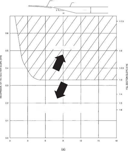
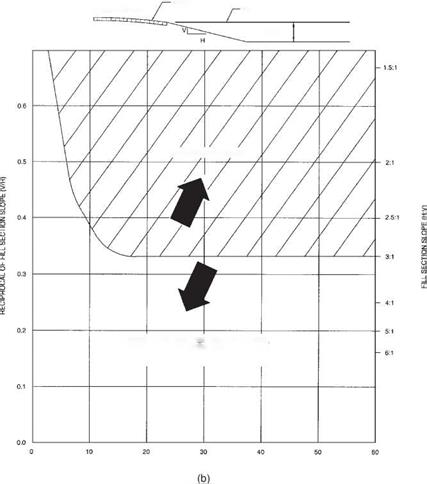
As indicated in Fig. 6.12, the main factors considered in determining the need for barriers are the embankment height and the side slope. These criteria are based on studies of the severity of encroachments on embankments as compared with impacts with roadside barriers. The figure does not include the probability of an encroachment or relative costs. Some states have made their own studies and developed charts having a series of curves for different traffic densities.

Подпись: SHOULDER
Подпись: TRAVELED WAY
Embankments
Подпись: BARRIER WARRANTED
Подпись: BARRIER NOT WARRANTED FOR EMBANKMENT. HOWEVER, CHECK BARRIER NEED FOR OTHER ROADSIDE OBSTACLES.

EmbankmentsFILL SECTION HEIGHT (m)

FIGURE 6.12 Embankment warrants based on comparative risk analysis. (a) SI units; (b) U. S. Customary units. (From Roadside Design Guide, AASHTO, Washington, D. C., 2002 and 2006, with permission)

WARRANTS FOR ROADSIDE BARRIERS

Longitudinal roadside barriers are used to shield motorists from natural or human – made obstacles located along either side of the traveled way, and sometimes to protect pedestrians and bicyclists. Median barriers and barrier end treatments are discussed separately in Arts. 6.9 and 6.12.

Barriers must contain and redirect vehicles. Because of the complicated dynamic behavior involved, the most effective way to ensure performance of new designs is through full-scale crash testing. Standard crash tests are presented in NCHRP Report 350, “Recommended Procedures for the Safety Performance Evaluation of Highway Features.” To match barrier performance to service needs, a series of six test levels are recommended to evaluate occupant risk, structural integrity, and postimpact vehicle behavior. Various vehicle masses, velocities, and impact angles are included. To view acceptance letters for longitudinal barriers under NCHRP 350, visit the FHWA web site, http://safety. fhwa. dot. gov/fourthlevel/hardware/longbarriers. htm.

NCHRP Report 350 establishes six test levels (TLs) for longitudinal barriers to evaluate risk, structural integrity of the barrier, and vehicle postimpact behavior. A range of vehicle weights (masses), speeds, and impact angles are addressed. The AASHTO Roadside Design Guide provides the following description:

TL-1, TL-2, and TL-3 require successful tests of an 820 kg (1800 lb) car impacting a barrier at an angle of 20 degrees and a 2000 kg (4400 lb) pickup truck impacting a barrier at an angle of 25 degrees, at speeds of 50 km/h, 70 km/h and 100 km/h (30 mph, 45 mph, and 60 mph), respectively. TL-4 adds an 8000 kg (17,600 lb) single-unit truck at an impact angle of 15 degrees and 80 km/h (50 mph) to the TL-3 matrix. TL-5 substitutes a 36,000 kg (80,000 lb) tractor-trailer (van) for the single-unit truck and TL-6 substitutes a 36,000 kg (80,000 lb) tractor-trailer (tanker). (p. 5-1)

Barriers typically go through an experimental phase in which a barrier that has passed crash test evaluation is subjected to an in-service evaluation, and an opera­tional phase in which a barrier that has proven acceptable in the in-service evaluation is used while its performance is further monitored. Barriers are also considered opera­tional if they are used for extended periods and demonstrate satisfactory performance in construction, maintenance, and accident experience.

The criteria by which the need for a safety treatment or improvement can be determined are termed warrants. Barrier warrants are based on the premise that traffic barriers should be installed only where they reduce the probability or frequency of potential accidents. Warrants may be based on a subjective analysis of roadside conditions or a benefit-cost study (life-cycle cost analysis). The latter can be used to rationally analyze factors such as design velocity and traffic volume in relation to barrier needs and associated costs and accident costs.. Three options may be evaluated:

• Remove or reduce the area of concern so that it does not require shielding.

• Install an appropriate barrier.

• Leave the area unshielded.

The last of these options would usually be cost-effective only where the accident probability is low.

The main uses of roadside barriers are to shield either embankments or obstacles, as discussed below. Barriers may also be used to protect pedestrians, school yards, or bicyclists. There are no firm criteria for these applications, and each must be evaluated on its own merits.