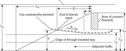
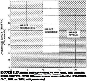
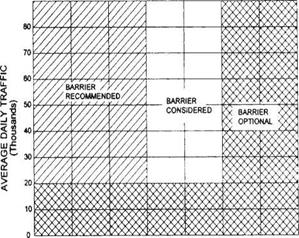
Like roadside barriers, median barriers can be classified as flexible, semirigid, or rigid as indicated in Table 6.7. Figures 6.26 through 6.35 show details of these various types of median barriers and factors to be considered in selection and application. Additional comments on several of the systems follow. In many of their characteristics they are similar to their roadside barrier counterparts.
Typical three-strand cable systems (Fig. 6.26) should be used only if there is adequate deflection distance, about 12 ft (3.5 m) in each direction. Performance is sensitive to mounting height. Proper end anchorage is critical. They are not well suited for areas hit frequently, on sharp curves, and on facilities with high truck volumes.
 |
|
|
|
|
|
|

|
TABLE 6.7 Classification of Median Barriers and Approved Test Levels
|
Barrier system
|
Test level
|
|
Flexible systems
|
|
|
Three-strand cable (weak-post)
|
TL-3
|
|
High-tension cable (weak-post)
|
TL-3
|
|
W-beam guardrail (weak-post) Semirigid systems
|
TL-2
|
|
Box beam (weak-post) Blocked-out W-beam (strong-post)
|
TL-3
|
|
Steel or wood post with wood
|
TL-3
|
|
or plastic block Steel post with steel block
|
TL-2
|
|
Blocked-out thrie-beam (strong-post)
|
|
|
Wood or steel post with wood
|
TL-3
|
|
or plastic block
|
|
|
Modified thrie-beam
|
TL-4
|
|
Rigid systems
|
|
|
Concrete barrier
|
|
|
New Jersey shape
|
|
|
32 in (810 mm) tall
|
TL-4
|
|
42 in (1070 mm) tall F-shape
|
TL-5
|
|
32 in (810 mm) tall
|
TL-4
|
|
42 in (1070 mm) tall Single-slope
|
TL-5
|
|
32 in (810 mm) tall
|
TL-4
|
|
42 in (1070 mm) tall Vertical wall
|
TL-5
|
|
32 in (810 mm) tall
|
TL-4
|
|
42 in (1070 mm) tall
|
TL-5
|
|
Quickchange® movable barrier
|
TL-3
|
|
(including SRTS and CRTS)*
|
|
*SRTS refers to the steel reactive tension system; CRTS refers to the concrete reactive tension system.
Source: From Roadside Design Guide, AASHTO,
Washington, D. C., 2002 and 2006, with permission.
|
Deflection can be reduced by decreasing post pacing. The system shown meets the TL-3 requirements.
High-tension cable systems are installed with significantly greater cable tension. They reduce deflections to 6.6 to 9.2 ft (2 to 2.8 m) and often show less damage after impact. Several proprietary systems have been accepted by the FHWA.
The W-beam (weak-post) system (Fig. 6.27) is sensitive to mounting. Proper end anchorage is essential. It is not well suited where terrain irregularities exist or where frost heave or erosion is likely to alter the mounting height by more than 2 in (50 mm). However, it is suitable for relatively flat, traversable medians without curbs or ditches that could affect vehicle trajectory. This is a Tl-2 system.
The box-beam (weak-post) median barrier (Fig. 6.28) is a TL-3 system, most suitable for traversable medians with no significant irregularities. Posts have to be repaired after most hits to maintain correct beam height, so it should not be used in areas where it is likely to be frequently hit.

None (the former single-strand cable “MBI” is obsolete)
TD3
S3 x 5.7 steel 16 ft
V4-in-dia. steel cable 30 in 11 ft-6 in
Remarks: Because of the high dynamic deflection for cable systems, they are not recommended for use in medians narrower than approximately 23 ft, nor in medians which contain rigid objects. The extensive damage done during moderate to severe impacts leaves a significant length of barrier inoperative until repairs can be made. Cable median barrier systems are recommended for use on irregular terrain and on wider medians where the need is only to prevent infrequent, potentially catastrophic cross-median crashes. For proper performance it is essential that this system be installed and maintained at the correct mounting height. This system is similar to the 3-strand cable roadside barrier, except that one of the cables is mounted on the opposite side of the post from the other two.
FIGURE 6.26 Three-cable median barrier. Conversions: 1 in = 25.4 mm, 1 ft = 0.305 m. (From Roadside Design Guide, AASHTO, Washington, D. C., 2002 and 2004, with permission)
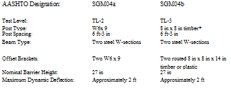
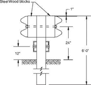
The blocked-out W-beam (strong-post) median barrier meets TL-3 or TL-2, depending upon the post type and blocking used. Figure 6.29 shows several variations of the system. Mounting heights of 30 in (760 mm) are sometimes specified but have not been tested. A separate rub rail (usually a steel channel or tube) has sometimes been added to minimize postsnagging problems with the higher mounting height.
The blocked-out thrie-beam (strong-post) median barrier meets TL-3 and the modified thrie-beam meets TL-4. The post type and blocking used affect the rating (Fig. 6.30). The thrie-beam is capable of accommodating a larger range of vehicle sizes than the W-beam because of its greater beam depth. Also, the deeper beam eliminates the need for a rubrail.
The concrete safety shape (Fig. 6.31) is the most common rigid median barrier because of low cost, effective performance, and low maintenance. Approved shapes include the New Jersey and F-shaped barriers, the single-slope barrier, and the vertical wall barrier.
Remarks: This barrier system is suitable for wide, flat medians where sufficient space is available to accommodate deflections. In order to place rigid objects within the median, the SGM02 must be divided into parallel SGR02 barriers with the objects centered in a 23-ft-plus gap or be transitioned to a semirigid system.
FIGURE 6.27 W-beam (weak-post) median barrier. Conversions: 1 in = 25.4 mm, 1 ft = 0.305 m. (From Roadside Design Guide, AASHTO, Washington, D. C., 2002 and 2006, with permission)
When adequately designed and reinforced, all of these meet the requirements of TL-4 at the standard height of 810 mm (32 in) and TL-5 at heights of 1070 mm (42 in) and higher. The New Jersey and F-shape barriers (Fig. 6.31), commonly referred to as safety shapes, differ in the height of the break point (change of slope of the face). The F-shape may perform better with regard to vehicle roll when subjected to small vehicle impact. When pavement overlays exceed 3 in (75 mm), the height of the concrete above the break point must be increased to maintain an adequate height. Figures 6.32 and 6.33 show tall-wall safety-shape barriers (reinforced and nonreinforced concrete) that have been used successfully. The single-slope barrier (Fig. 6.34) offers an advantage over others in that the pavement next to it can be overlaid several times, reducing the height to 42 in (1070 mm), without affecting performance. Foundation requirements do not appear critical, and there are many variations. Concrete median barriers can be slipformed, precast, or cast in place. A sand-filled metal version has been used in several states on an experimental basis.
Two important factors for safety-shape concrete barriers should be noted. Although the barrier does not deflect when hit, passenger vehicles may become airborne and even reach the top in high-angle, high-speed impacts. Fixed objects on top of the barrier such as luminaire supports can cause snagging. Also, even for shallow-angle

A ASHTO Designation:
Test Level:
Post Type:
Post Spacing:
Beam Type:
Offset Brackets:
Mountings;
Nominal Barrier Height:
Maximum Dynamic Deflection:
Remarks: This barrier system is suitable for both wide and narrow medians and locations where the terrain is moderately irregular. Even moderate vehicle impacts cause a large number of posts to be damaged, Temporary supports may be used to maintain beam height until posts are replaced.
FIGURE 6.28 Box-beam median barrier. Conversions: 1 in = 25.4 mm, 1 ft = 0.305 m. (From Roadside Design Guide, AASHTO, Washington, D. C., 2002 and 2006, with permission) impacts, the roll angle of a high-center-of-gravity vehicle may be great enough to permit contact of the cargo box with objects on or just behind the barrier. Taller barriers offer improved characteristics in this regard.
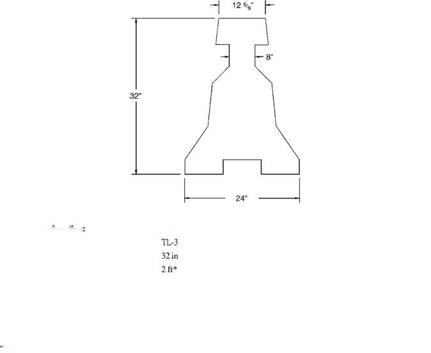
The movable concrete barrier is an F-shaped barrier furnished in lengths of 37 in (940 mm) and arranged in a chain fashion with ends joined by pins. The proprietary Quickchange® system is shown in Fig. 6.35. The T segment at the top facilitates lifting. The system is often used in construction zones where traffic lanes are opened and closed frequently. Various other systems are available.


 AASHTO Designation
 AASHTO Designation:


