Rigid Systems
The concrete safety shape system (Fig. 6.21), which has a sloping front face, is similar to the concrete median barrier (Art. 6.9.1) but usually has a vertical back face. The reduced cross-section of the roadside barrier version makes it more vulnerable to overturning, thus requiring more reinforcing steel and/or a more elaborate footing design. The New Jersey shape at a height of 32 in (810 mm) meets TL-4 and at a height of 42 in (1070 mm) meets TL-5. Both the New Jersey profile and the F-shape profile shown in Fig. 6.21 are acceptable. The F-shape reportedly showed better performance in crash tests with 1800-lb (820-kg) cars and 18,000-lb (8000-kg) single-unit trucks. Higher designs have been tested and constructed to redirect heavy vehicles. For example, the

 |
None
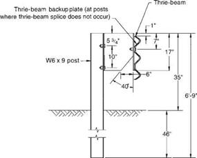
W6 x 9 steel or 6 in x 8 in wood M14 x 18 steel 6 ft-3 in
12-gage thrie-beam 34 in
Approximately 3 ft for a 20,000-pound school bus (56 mph, 15° impact angle)
Remarks: Modified thrie-beam was first installed in Rhode Island, Colorado, Nebraska, and Michigan as an experimental barrier. Since that time, it has been reclassified as an operational system, requiring virtually no repair for shallow-angle hits. This barrier can accommodate vehicles ranging in size from 1700-lb subcompacts to a 33,000-lb intercity bus,
FIGURE 6.19 Modified thrie-beam roadside barrier. Conversions: 1 in = 25.4 mm, 1 ft = 0.305 m. (From Roadside Design Guide, AASHTO, Washington, D. C., 2002 and 2006, with permission)
version shown in Fig. 6.21a is 90 in (2290 mm) high; also, it is sloped on both faces. It contains impacting tractor-trailers but has not completely eliminated rollovers. Successfully testing to TL-6 has been reported. The version shown in Fig. 6.21b is 64 in (1630 mm) high. Apparently effective, it is buttressed by an earth berm on the back side and topped with a W-beam barrier. Constant slope and vertical wall barriers have also been successfully tested (Art. 6.9.1).
The stone masonry wall system (Fig. 6.22), with a reinforced concrete core and a facing of stone and mortar, offers another aesthetic alternative for parks and similar applications. This barrier meets TL-3. Alternative systems with precast units are also available.


Leave a reply