Posted by admin on 20/ 11/ 15
IMAGINE MARION WILLOUGHBY,
sitting on the rotting front porch of his leaking rental house, listening to Habitat’s offer to have volunteers help him build a new home. Imagine him hearing that Habitat will sell the new house to him at cost and also give him a mortgage with 0% interest.
Marion did not believe a house could be built in just one week. But his opinion began to change when he saw the Habitat volunteers arrive in the pouring rain with a 40-ft. horse trailer packed with enough gear for a
crew of 30 members. Marion began to believe that a miracle might happen in just six days.
I can’t count how many times that week he said, “You don’t see ladies doing this kind of work!” and “This is such a blessing!” and “You people do it right!” Marion was amazed that a crew of accountants, lawyers, judges, flight attendants, computer programmers, mothers, and grandmothers could build a house—and that they cared enough to come to Georgia to build a house for him.
The house cost $50,000. But it took much more than money to build Marion Willoughby’s house. It took months of planning, two days of travel, and six days of hard work. Was it worth it? There’s no doubt in my mind that Marion would answer with an emphatic “Yes!” And so would the many volunteers and staff who helped make it possible. Because, when it comes right down to it, providing decent housing for another human being is an experience that enriches everyone who lends a hand.
-Anna G. Carter
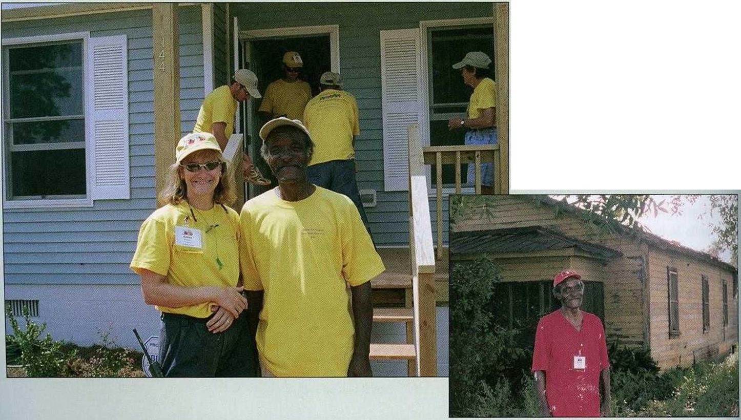 Habitat for Humanity and its volunteers have changed Marion Willoughby’s life for the better. His new home is safe, warm, Habitat for Humanity and its volunteers have changed Marion Willoughby’s life for the better. His new home is safe, warm,
and dry. [Photo © Anna G. Carter.]
BUILDING A DECK FRAME
Posted by admin on 20/ 11/ 15
Many builders like to use flashing when installing a ledger. Find out which types of flashing builders use in your area. I tend to use heavy-gauge aluminum behind the ledger, though I sometimes opt for high-quality galvanized sheet metal or even copper—expensive though it is—instead of aluminum. Although it can take a while, ocean air and city smog will gradually take their toll on aluminum flashing, causing it to deteriorate.
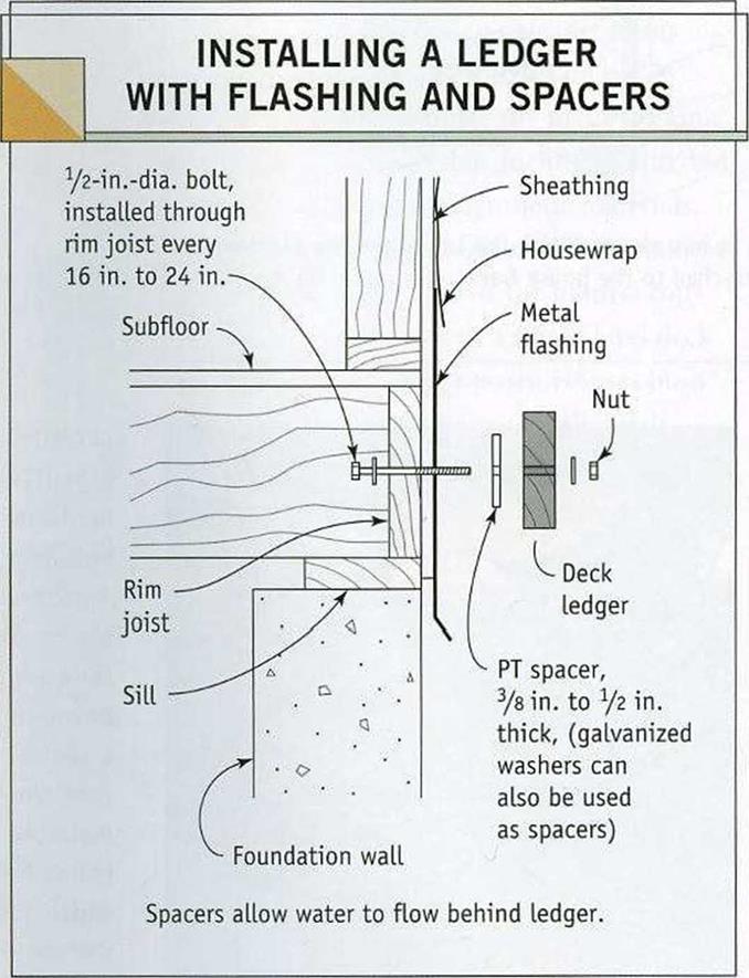
The flashing is installed before the exterior siding. It can be nailed directly to the wall framing and rim joist if no sheathing has been used on the exterior walls. Otherwise, install the flashing on top of the wall sheathing (see the illustration at left). Order flashing that is wide enough to extend several inches above the ledger and down over the rim joist. At door openings, cut the flashing just enough to bend it over and lay it flat on the subfloor. Use as few nails as possible when installing flashing, and keep them high on the wall. The ledger and exterior siding will hold the flashing in place. If you install housewrap (such as Tyvek® or Barricade®) over the wall sheathing,
       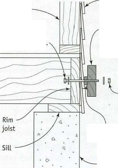   make sure the flashing tucks underneath the housewrap, as shown in the illustration. make sure the flashing tucks underneath the housewrap, as shown in the illustration.
In the dry Southwest, the ledger can be fastened directly on top of the flashing. Otherwise, use galvanized washers or PT shims to create a narrow (%-in. to!4-in.) drainage space behind the ledger. This prevents buildup of moisture or mold.
INSTALLING A LEDGER WITHOUT FLASHING.
Here’s how to install a ledger against fiber – cement siding, wooden clapboards, or Tl-11 siding without using flashing. Simply install the siding in the normal fashion, and hold the ledger away from the siding with PT wood spacers or galvanized washers. I’ve installed ledgers this way on a number of houses, including Habitat projects. To account for the angle of wood or fiber-cement clapboards, cut an angled PT spacer or use galvanized washers in the manner shown in the illustration at right. For that technique, first install the spacers, then bolt the ledger loosely in place. Complete the deck framing, then tighten the ledger installation bolts.
Nails won’t do when installing a ledger, though you can drive a few just to hold the board in position. My preference is to attach the ledger with И-in.-dia. bolts that extend through the rim joist and are held fast with nuts and washers. Make sure the ledger is level before you begin boring holes for the bolts. Space bolts 16 in. to 24 in. apart. As extra insurance against unwanted water, apply some silicone caulk in each hole before inserting the bolt through the rim joist. Insert the bolts through the rim joist from the back, making sure you place a washer beneath each bolt’s head and nut.
і ————– 1
Helping Hand
Larger decks may require more bolts to attach the ledger to the house frame. You have to think about the weight a deck might carry— a party with 50 people on a deck is a lot of weight.
Posted by admin on 20/ 11/ 15
Helping Hand
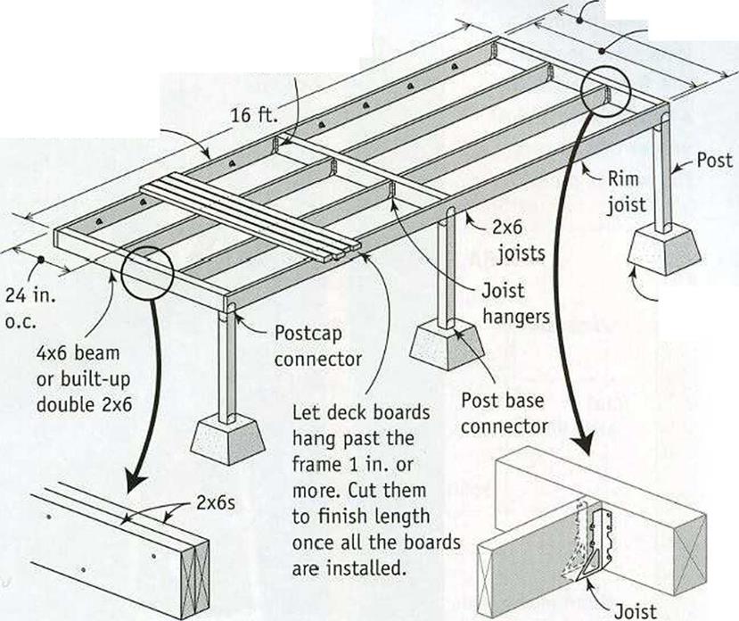
Framing connectors are worth checking out. If you haven’t discovered the vast variety of framing connectors that are available, try to do so before building a porch or a deck. A well – stocked lumberyard or building supplier will sell connecting hardware designed to reinforce all kinds of joints among different framing members.
 STEP 2 Install the Ledger STEP 2 Install the Ledger
On a house built over a basement or crawl – space, a deck or porch can be attached to the house frame. Deck building then becomes a lot like framing a floor-joist system inside a house (see chapter 3). Step one in this process is to attach a ledger to the house frame. Straight, level, and solidly secured to the house, the ledger acts like a rim joist for the porch. It extends the full length of the porch, supporting its inboard side.
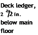
There are several concerns when attaching a ledger, and all of them are important. First, the ledger must be at least 2A in. below the level of the interior floor. When ІИ-іп. deck boards are screwed on top of the ledger, the deck will be 1 in. lower than the interior floor, which is just about right. If wheelchair accessi
bility is a concern, plan to build a small ramp to bridge the distance between the deck and the doorsill.
Reserve your best boards to use as ledgers—clear lumber with straight, square edges and no major imperfections (cracks, large knots, or warping). When installing a ledger, make sure water cannot get behind the ledger and into the house frame, where it could cause rot. And make sure the ledger is secured to the house in a manner that will hold for the life of the building.
Posted by admin on 20/ 11/ 15
|
THE PORCHES ON HABITAT HOUSES ARE AMONG THEIR NICEST FEATURES. AH
Habitat houses have a covered porch of some sort. On the Charlotte house, there’s a small porch tucked underneath the main roof, sheltering the main entry door. The side door has a landing that could grow into a larger deck sometime in the future (see the photo on the facing page). Most of the Habitat houses I’ve worked on out West have a porch as an attached structure. It has its own roof, which joins either the main roof or the gable end of the house (see the photo on p. 176). In almost any form, a porch adds something special to a house. Its a place to put some flowers, kick off your shoes when you get home from work, or just sit down and relax at any time of day.
I have built hundreds of decks and porches over the years, and IVe noticed that people are more inclined to use them if they are 6 ft. wide or more. Narrower than that and all you really have is a walkway or a landing. IVe also noticed that a deck with a roof—a porch, in other words—seems to get more use than a deck that’s open to the elements. In northern regions, a porch can be enclosed and used as a mud – room in the winter. In southern states, porches are often screened to keep out insects.
 |
|
1 Complete the Essential Roof Framing
2 Install the Ledger
|
|
|
|
|
5 Install the Decking and Stair Treads
|
|
|
|
|
3 Install the Foundation and Floor Framing
|
|

|
|
|
|
|
■ JU і 1-і-і
|
|
|
ggjjgfe:
|
|
""•’ Мш ГІР
|
|
/1
|
|
^ і
|
1
|
|
|
|
|
![Basic Design for Porches, Decks, and Landings Подпись: A PORCH CREATES AN OUTDOOR LIVING ROOM. A small house can live large when a porch is part of the design. On this Habitat project, the porch shelters the main entry. [Photo ®Lany Haun.]](/img/1312/image645.gif)   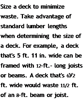
Design Ideas
for Decks and Porches
No matter what size deck or porch you decide to build, quite a few design considerations deserve attention (see Resources on p. 278). Take some time to evaluate the many decking materials that are available, including different types of solid wood and synthetic materials.
On a sloping site, its often better to build a multilevel deck that follows the natural contour of the land instead of a single-level deck that requires tall support posts. Houses built on a concrete slab can have a smaller slab poured to create a porch or patio area. Just make sure the slab is l in. or so below the floor slab to keep water from entering the house. To promote drainage, pour the slab with a slight slope, about / in. per ft. Don’t forget to thicken the concrete and install a metal post base where the posts will be installed to hold the supporting roof beams.
Before you begin to build, you should also know which railing design you plan to use. Drive around a few neighborhoods and you’ll certainly come upon some interesting railing designs to inspire your own efforts. Finally, consider your electrical wiring needs. Overhead light is important for security reasons, but you may also want to install some low – voltage lights on or around the porch or in nearby walkway or garden areas.
STEP 1 Complete the Essential Roof Framing
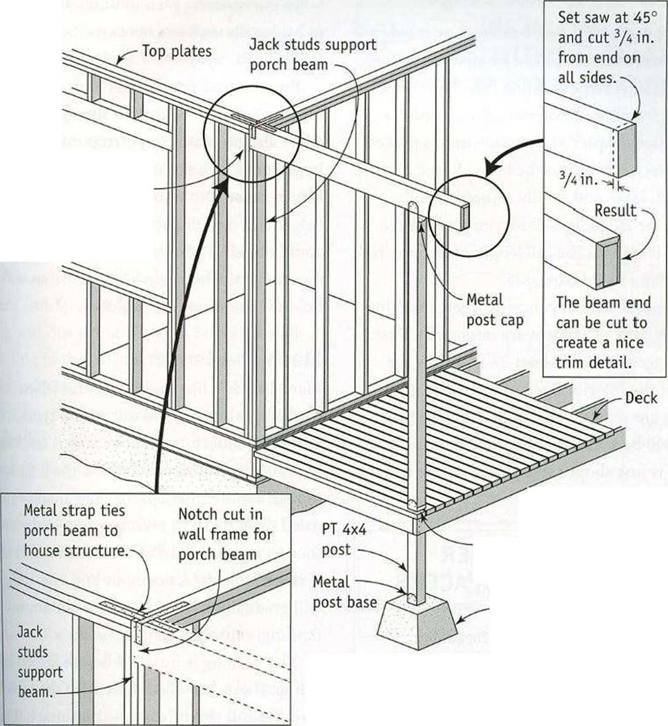
In many house designs, a section of the main roof extends over the porch. To complete the installation of the roof trusses, roofing material, and exterior trim, the truss support beams over the porch must be cut and fastened to the wall framing. As shown in the illustration on the facing page, each beam rests in a pocket formed by a pair of jack studs framed in the house wall. The top of the beam is flush and level with the top of the wall plates.
in addition to nailing the beam to the wall framing, I strengthen the connection by nailing a metal strap across the top of the beam and the double top plate of the wall. Beams made from rough 2x lumber can later be covered with aluminum cladding, as described in chapter 6.
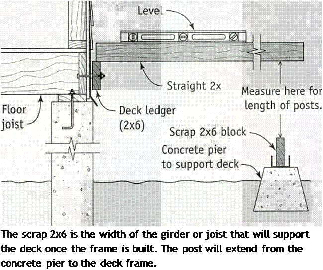
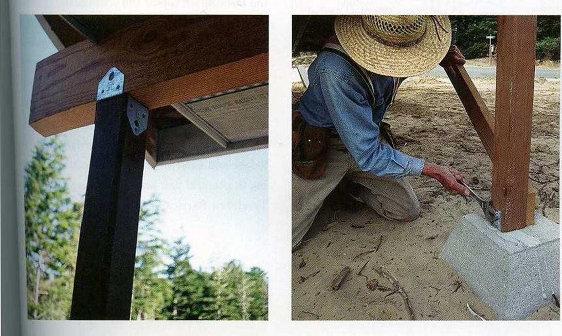
If it’s not possible to install permanent posts at this stage, temporary posts can be used to support porch ceiling beams. When you install permanent posts, be sure to secure them with framing connectors—a post base at the bottom and metal connectors at the top that are fastened to the post and to the beams (see the photos on the facing page).
176] BUILDING AN OUTDOOR ROOM
Posted by admin on 20/ 11/ 15
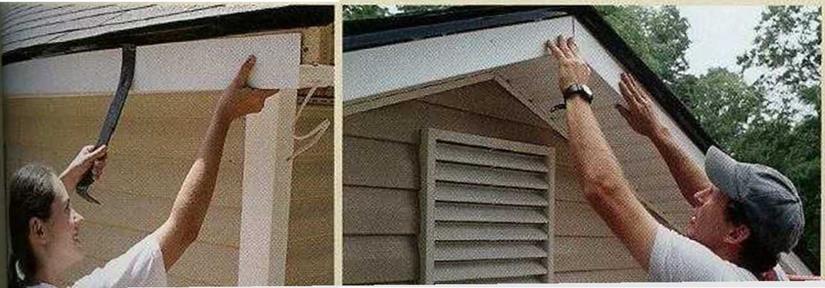
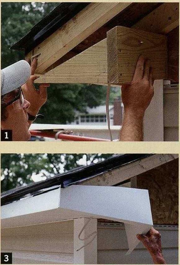
COMBINING AN ENCLOSED SOFFIT with a gable – end roof overhang means that you need to construct a boxed return. The return creates the nailing surfaces required to bring the soffit and fascia trim around the corner of the house. Here’s how to do the job:
1. Use 2x lumber to make the framing for the boxed return, which consists of a triangular piece cut to match the roofs pitch and a straight board that vertically extends to the gable wall.
2. Fasten this assembly to the bottom edge of the barge rafter and the back wall. The soffit paneling must be attached prior to the aluminum cladding.
3. Run electric cable through the corner soffit for an outdoor light. Slip the gutter board cladding under the roofs drip edge trim, then bend it at a 90-degree angle to cover the end of the soffit. Test- fit the cladding for the return before you nail the prebent piece in place.
4. To install gable-end siding panels, nail white J-channel trim along the rake. Trim the panel ends to match the roofs pitch.

STEP 8 Cover Exterior Trim with Aluminum Cladding
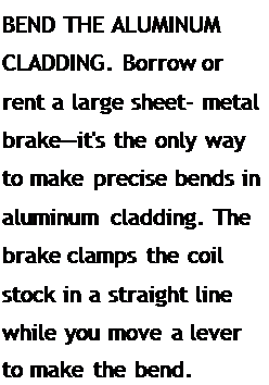
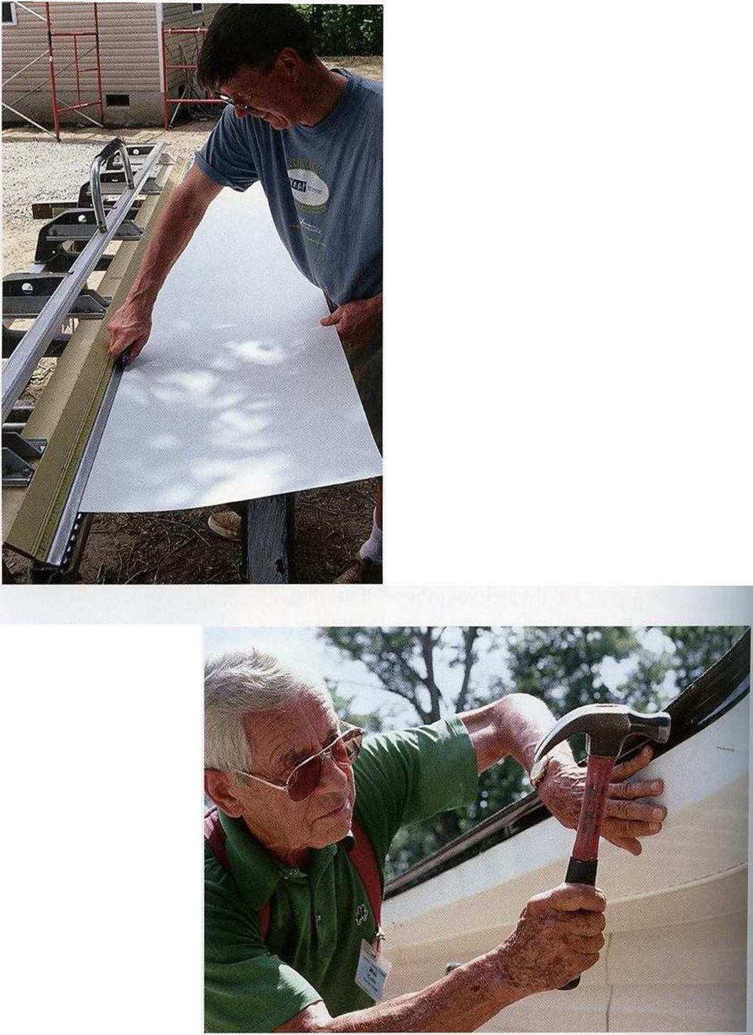
Aluminum trim, often referred to as coil aluminum because it comes in a coil or roll, can be shaped and used to cover rough exterior trim, such as gutter boards, barge rafters, and beams. This sheet metal comes in various widths and colors. The small nails used to install the material are available in matching colors. Softer than steel, coil aluminum can be cut with tinsnips or a utility knife. The same long, flat worktable that was used during vinyl siding installation is just as valuable for sheet – metal work. To make the precise bends that give the finished cladding its clean-lined
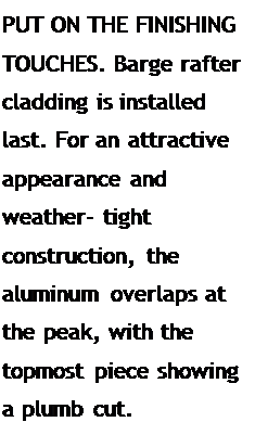
We have to set up scaffolding to finish the siding and soffit work; by this time, the house is really looking great. . .
After a break to admire our progress (and cleanup the spare pieces of vinyl siding)f we start to cut aim bend the aluminum cladding that will cover the fasti boards and the barge rafters. . .

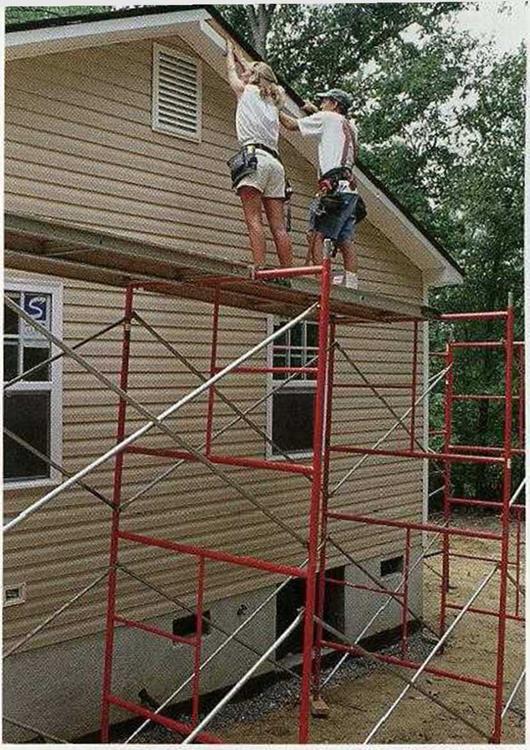  
appearance, you 11 need a hand brake as well as a large sheet-metal brake, which you can borrow or rent (see the top photo on the facing page).
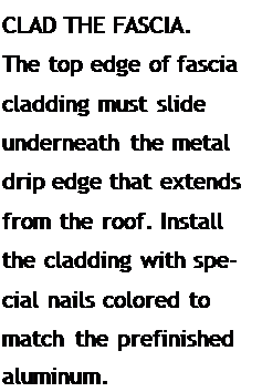
To wrap a 2×4 gutter board, cut a 6-in.- wide strip of aluminum and bend it at 4 in. into a 90-degree angle. The 4-in. leg slips under the roofs drip cap and covers the front of the gutter board. Attach it with matching 1-in.-long nails every 24 in. along an imaginary centerline (see the center photo on the facing page). The 2-in. leg fits over the vinyl soffit, covering the nails used to secure the soffit to the bottom of the gutter board. Be careful not to drive nails so hard that you leave a hammer imprint in the metal.
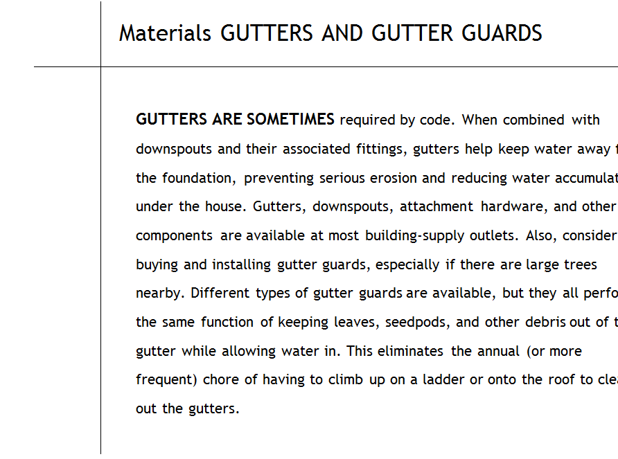
The cladding that covers the boxed return is a bit more complex, but the bends can be made with a hand brake. At the ridge peak, run one piece of aluminum past the center – line, then cut the second piece plumb to give the trim a finished appearance.
Any time you use aluminum to cover gutter boards, posts, or beams, make absolutely sure that no water can get behind the aluminum. You can do this by overlapping adjacent sections of cladding by 3 in. to 4 in. and by ensuring that a higher section of cladding (on a barge rafter, for example) always overlaps a lower section.
A big bending tool, called a brake, creases the aluminum perfectly straight… When it slides into place over the wood, it looks like it belongs there.
Posted by admin on 20/ 11/ 15
GABLE WALL
Soffit (unvented) Barge rafter Roof shingles
Metal drip edge
2-in. gap Baffle Double above baffle J top plate for ventilation
STEP 7 Finish the Soffits
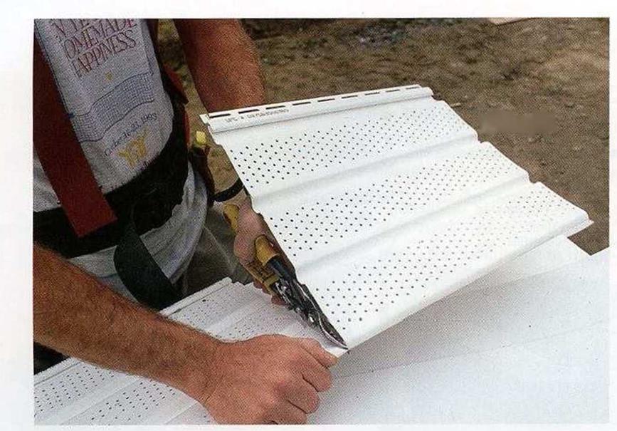
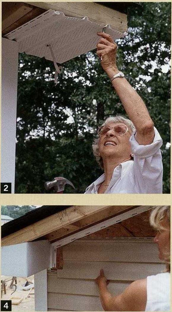
   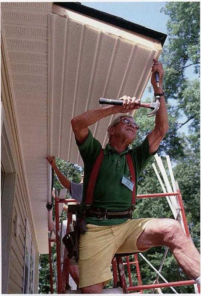 Vinyl soffit material has small holes to allow air to enter freely. Before attaching this material along eave walls, make sure that all the baffles between rafters are in place to keep insulation out of the eaves and allow airflow into the attic. On this house, we cut the vinyl soffit sections into short lengths that overlap each other and ran them perpendicular to the siding. Insert the ends of each soffit panel into vinyl J-channel trim nailed to the wall and nail the other end to the bottom edge of the gutter board (see the illustration on p. 169). Vinyl soffit material has small holes to allow air to enter freely. Before attaching this material along eave walls, make sure that all the baffles between rafters are in place to keep insulation out of the eaves and allow airflow into the attic. On this house, we cut the vinyl soffit sections into short lengths that overlap each other and ran them perpendicular to the siding. Insert the ends of each soffit panel into vinyl J-channel trim nailed to the wall and nail the other end to the bottom edge of the gutter board (see the illustration on p. 169).
Gable-end soffit details
Soffit work is also required to finish off the underside of the roof overhang on the gable ends of a house. Remember the J-channel trim that you installed along the rake to house the ends of the gable-wall siding panels? The inboard edge of the soffit trim can rest right on top of that J-channel. This detail is shown in the illustration on p. 169. The outboard edge of each soffit piece is nailed to the 2x2s fastened along the barge rafter.
 It’s common practice for some builders to build boxed returns at the bottom corners of the roof to bring the soffit around the corners of walls. One part of the return (made from 2x material) is cut to match the angle of the roof’s pitch and is fastened to the underside of the barge rafter. The other part of the return is fastened to the angled piece and to the wall (see the sidebar on the facing page). It’s common practice for some builders to build boxed returns at the bottom corners of the roof to bring the soffit around the corners of walls. One part of the return (made from 2x material) is cut to match the angle of the roof’s pitch and is fastened to the underside of the barge rafter. The other part of the return is fastened to the angled piece and to the wall (see the sidebar on the facing page).
Posted by admin on 20/ 11/ 15
The last piece of siding at the top of an eave wall can be fastened in different ways. If the eaves will be left open, use strips of undersill trim and cut and fasten the final panel in the same way as the one under the window. If the eaves will be closed with soffit material (as was done on this house), the uppermost sid
ing panel can simply be nailed in place above the level of the soffit. The J-channel trim for the soffit, and then the soffit itself, will cover the top siding panel.
Siding gable-end walls
Begin by nailing 2×2 blocking between the lookouts and along the barge rafter, as shown in the illustration on the facing page. This allows J-channel to be nailed up the rake, where it can receive the angled ends of the siding panels. Some builders prefer to hold the J-channel Zi in. down so the soffit pieces can simply lie on top of it, as shown in the illustration.
To ensure accurate angled cuts where the siding panels meet the rake, make a pattern from a short scrap of vinyl siding, with the angle cut to match the roof’s pitch. If you really want to save time, however, set up a circular saw guide at the proper angle on the worktable.
As you cut and fit these pieces on the gable end, be sure to leave a 14-in. space between the siding and the inside of the J-channel. If there are gable-end vents, cut and fit pieces around the vents, just as you did for those around the windows and doors. The last small piece at the peak can be cut and secured to the wall with a small screw or nail.
  The vinyl soffit panels are filled with small holes so air can pass into the attic space. . . The vinyl soffit panels are filled with small holes so air can pass into the attic space. . .
They finish off the eaves nicely. . .
|
С/Э

|
|
Posted by admin on 20/ 11/ 15
PRECISE CUTOUTS ARE SOMETIMES REQUIRED
for certain situations, such as fitting siding panels over vents or electrical outlet boxes. Careful layout is the key here.
1. Place the siding panel directly below where it will be installed. Mark where the sides of the box hit the panel.
2. Reposition the panel to one side of the box, clipping it into the panel just below the box. Mark where the top and bottom of the box hit the panel.
3. Outline the cutout where the horizontal and vertical lines intersect, then cut the opening with a sharp utility knife.
The panel is now ready to install.
 
side for expansion. These notched cuts can be made with a utility knife, a hacksaw, or tin – snips. Use a snap-lock punch to create crimps, I or tabs, lA in. down from the top edge of the I notched siding and make crimps every 6 in. across the length of the window. The crimps must face out to lock into the undersill trim.
The panels that fit over the tops of windows and doors are marked and notched in the same way as those on the bottom. The horizontal part of the siding slips down into the J-channel. To make cutouts where the siding fits over a dryer vent, an electrical outlet box, or another protrusion, use the techniques discussed above and on the facing page.
| |




![]()
![]()



 metal cleats are also available, if you prefer.



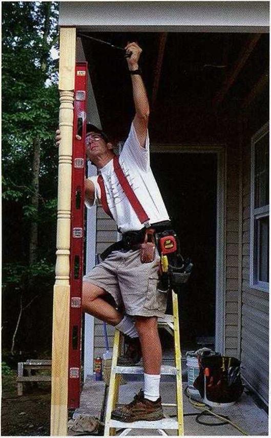

 posts. Stretch a chalkline from the ends of the two end beams across the interior beams and snap a line. Cutting the interior beams to length in this manner ensures a straight rim joist in the front.
 Habitat for Humanity and its volunteers have changed Marion Willoughby’s life for the better. His new home is safe, warm,


 make sure the flashing tucks underneath the housewrap, as shown in the illustration.


![POST-AND-BEAM SUPPORT FOR A PORCH ROOF Подпись: FRAMING CONNECTORS ARE ESSENTIAL. Steel connecting hardware is required when building a porch or a deck. A post cap connector (see the photo far left) is useful for strengthening the joint between a porch post and a roof beam. A post base (see the photo near left) is mounted on a concrete pier; it has holes for lag bolts, which fasten it to the post. [Photo far left ~ Larry Haun; photo near left ® Memo Jasso/Brown Studio.]](/img/1312/image657_0.gif)


![Basic Design for Porches, Decks, and Landings Подпись: A PORCH CREATES AN OUTDOOR LIVING ROOM. A small house can live large when a porch is part of the design. On this Habitat project, the porch shelters the main entry. [Photo ®Lany Haun.]](/img/1312/image645.gif)




 Vinyl soffit material has small holes to allow air to enter freely. Before attaching this material along eave walls, make sure that all the baffles between rafters are in place to keep insulation out of the eaves and allow airflow into the attic. On this house, we cut the vinyl soffit sections into short lengths that overlap each other and ran them perpendicular to the siding. Insert the ends of each soffit panel into vinyl J-channel trim nailed to the wall and nail the other end to the bottom edge of the gutter board (see the illustration on p. 169).
 It’s common practice for some builders to build boxed returns at the bottom corners of the roof to bring the soffit around the corners of walls. One part of the return (made from 2x material) is cut to match the angle of the roof’s pitch and is fastened to the underside of the barge rafter. The other part of the return is fastened to the angled piece and to the wall (see the sidebar on the facing page).
 The vinyl soffit panels are filled with small holes so air can pass into the attic space. . .

