Category Construction

MOISTURE, VAPOR & AIR BARRIERS

Notes

Coordinating these components is critical to avoid trapping water vapor in the wall cavity. The principle to follow is that the permeability (the degree to which water vapor will pass through a material) must be higher for materials on the cool side of the wall (usually the outside) than for materials on the warm side of the wall (usually the inside). For example, foil-faced rigid insu­lation, which has a very low permeability, should not be placed on the exterior in a cool climate. The chart below rates the permeability of common materials.

r

MATERiAL

PERMEABiLiTY (perms per STM-E96)

Foil-faced insulation

0

4-mil PVC

0.08

Extruded polystyrene

0.3-1.0

V2-in. CDX plywood

0.4-1.2

1/2-in. OSB

0.7

Kraft paper

1.8

15-lb. felt

5.6

V2-in. gypsum board

20

Building or house wraps

88-107

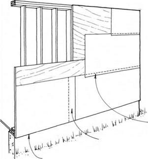
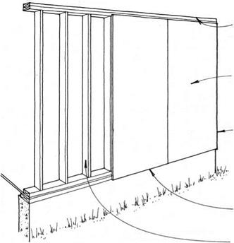
A moisture barrier under the siding is a sensible second line of defense to prevent water from reaching the frame of the building. Many products such as 15-lb. felt and bitumen-impregnated paper (which come in З-ft.-wide rolls, as shown here) have been used histori­cally and are suitable for this purpose.

A moisture barrier acting also as an air infiltration barrier under the siding must retard the passage of air and be impermeable to water, but allow vapor to pass. Polyolefin membranes, commonly called building or house wraps, meet these specifications and are the most prevalent barriers. They are veiy lightweight and come in rolls up to 12 ft. wide, allowing a single­story building to be covered in one pass. Building wraps can provide better protec­tion against air infiltration than felt and kraft paper because the wide rolls require fewer joints, and these joints are taped.

MOISTURE & AIR INFILTRATION BARRIERS

Installation

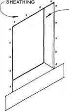
MOISTURE, VAPOR & AIR BARRIERSMOISTURE, VAPOR & AIR BARRIERSMOISTURE, VAPOR & AIR BARRIERSПодпись:Подпись: 3.) REPEAT STEP 2, BuT FOR TOP OF ROUGH OPENING. LEAVE OUTER EDGES UNSTAPLED FOR FUTURE INTEGRATION WITH WALL MOISTURE BARRIER.

2.) staple moisture

BARRIER To JAMBs of

rough opening & fold 6 IN. over sheathing & 6 IN. above & below rough opening.

note

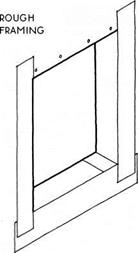
it is extremely important to wrap rough openings with a moisture barrier to protect the framing because this is where leaks are most likely to occur. the method shown here is adequate for limited exposure situations because ALL layers overlap to direct water away from the structural FRAME of THE BuiLDING. simpler methods may be employed where exposure to rain is not likely to occur, and more EXTREME methods (БЕЕ 89B) should BE employed WHERE exposure is severe. for the method shown here, many builders prefer to use thin moisture barriers THAT WILL not build uP WITH THE folds & WITH several layers.

MOISTURE, VAPOR & AIR BARRIERS

SHEAR WALL DESIGN CONSIDERATIONS

SHEAR WALL DESIGN CONSIDERATIONS

11 11


PLywOOD FLOOR

diaphragm


SHEAR WALL DESIGN CONSIDERATIONS

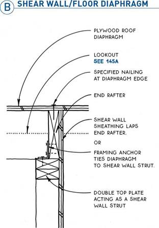
SHEAR wALL SHEATHING LAPS RIM jOIST,

OR

FRAMING ANCHOR TIES DIAPHRAGM TO SHEAR wALL STRUT.


FOUNDATION

WALL OR FLOOR ; ! STRUCTURE


Double TOP PLATE ACTING AS A SHEAR wALL STRUT


SPECIAL ANCHOR BOLT EMBEDDED IN FOUNDATION AND/OR CARRIED THROUGH FLOOR STRUCTURE PER MANUFACTURER’S INSTRUCTIONS


SHEAR WALL/ROOF DIAPHRAGM


SHEAR WALL/ROOF DIAPHRAGM


SHEAR WALL DESIGN CONSIDERATIONSSHEAR WALL DESIGN CONSIDERATIONSSHEAR WALL DESIGN CONSIDERATIONSSHEAR WALL DESIGN CONSIDERATIONS

SHEAR WALL DESIGN CONSIDERATIONS

SHEAR WALL DESIGN CONSIDERATIONS

DIAPHRAGM

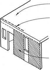
DRAG STRUT TIES MARGINAL PORTION OF DIAPHRAGM TO SHEAR WALL.


SHEAR WALL


SHEAR WALL DESIGN CONSIDERATIONS

SHEAR WALL DESIGN CONSIDERATIONS

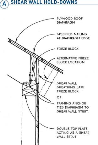
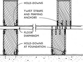
When shear walls are required on upper floors, they must be tied, through the floor diaphragm, to the shear walls below. If upper and lower shear walls align, their comers may be tied with hold-downs (see 86A) with the lower hold-downs inverted. If the shear walls do not align, their edges may be tied to the diaphragm with a combination of twist straps (for uplift) and framing anchors (for horizontal shear).

ґдЬ SHEAR WALL/SHEAR WALL_______

V—’ Tie between Floors

Drag struts are sometimes required to tie the dia­phragm to the shear walls, especially if the diaphragm is not bounded by shear walls at each end. A drag strut consists of a long metal strap firmly attached to the dia­phragm above the shear wall. The drag strut extends into the diaphragm in a line parallel to the shear wall to pull or “drag” the force from the diaphragm to the shear wall.

DRAG STRUT

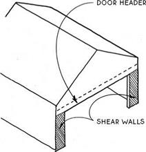
Подпись: GARAGE PORTAL FRAME Подпись: REINFORCED WINDOW

SHEAR WALL DESIGN CONSIDERATIONS

Garages with wide doors and limited walls are typical of buildings requiring shear walls. These condi­tions are so typical that several companies have devel­oped proprietary premanufactured walls specifically for garages. The shear walls are strapped to the door header and work in conjunction with it. Garage shear walls are also commonly site-built.

SHEAR WALL DESIGN CONSIDERATIONS

STIFF HEADER

STIFF COLUMN SHEAR PANEL

STRAPS TIE COLUMNS TO PANEL & HEADER.

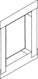
Engineers can design reinforced windows so the window can extend virtually from wall to wall in small buildings and building extensions. A shear panel below the window opening is strapped to stiff single-piece or built-up columns at the corners. The columns effectively cantilever up from the panel, stiffening the entire wall.

SHEAR WALL DESIGN CONSIDERATIONSПодпись: OVERLAP 4 IN. AT VERTICAL JOINTS.Подпись: ALIGN BOTTOM OF EDGE OF MOISTURE BARRIER WITH BOTTOM EDGE OF SHEATHING. sEE SPECIFIC SIDING TYPE FOR DETAILS.Подпись: OVERLAP 2 IN. TO 4 IN. AT HORIZONTAL JOINTS.SHEAR WALL DESIGN CONSIDERATIONSOnce the walls are framed and sheathed, they must be protected from moisture. This involves the installa­tion of a moisture barrier. The moisture barrier must be coordinated with an air barrier (to control air infil­tration), a vapor retarder (to control water vapor), and insulation.

A moisture barrier (also called a weather barrier or water-resistive barrier) is a membrane directly under the siding that prevents any water penetrating the siding from reaching the sheathing or the framing. An effective moisture barrier stops liquid water but lets water vapor through, thereby letting the wall breathe.

A vapor retarder (formerly known as a vapor barrier) is a membrane on the warm side of the wall (usually the interior) that retards the passage of water vapor from the warm inside air into the cooler wall, where it could condense (see 120).

An air barrier limits the infiltration of air through the wall. Either a moisture barrier or a vapor retarder may be detailed to seal the wall against air infiltration, thereby becoming an air barrier as well (see 120).

SINGLE-WALL CONSTRUCTION

Structural Sheathing

SINGLE-WALL CONSTRUCTIONSINGLE-WALL CONSTRUCTION

SINGLE-WALL CONSTRUCTION

SINGLE-WALL CONSTRUCTION

Подпись: 8-Ft. Panel Typical8-Ft. Panel with Water Table

Подпись: NONSTRUCTURAL SHEATHING

Подпись: (A GYPSUM SHEATHING

SINGLE-WALL CONSTRUCTION

NON-STRUCTURAL

SHEATHING.

SINGLE-WALL CONSTRUCTION

FULL-SIZE PANELS (AFT. X 8FT., 9FT, OR 10FT.) CAN PROVIDE STRUCTURAL

sheathing and/or FIRE resistance.

Many sheet materials that can be used for sheathing do not provide adequate lateral bracing. In addition to providing a base for a moisture barrier and siding, such nonstructural sheathings may also provide insulation or fire protection.

Insulative sheathings range in thickness from V2 in. to 1У2 in. They include fiberboards, foam plastic, and rigid fiberglass boards. R-values vary. Verify that the permeability of the sheathing is coordinated with the permeability of the vapor retarder (see 88A).

Siding must be nailed through nonstructural sheath­ings directly into the studs beneath them. The need for lateral bracing is often satisfied by applying plywood or other structural panels to the corners of a building, with less-expensive nonstructural sheathing elsewhere.

SINGLE-WALL CONSTRUCTION

Fire-protective sheathings are often required at walls on or near property lines, between attached dwellings, and between garages and living space. Type-X gypsum wallboard applied directly to the studs will satisfy most codes. Water-resistant gypsum board applied to the exterior of framed walls can also serve as an underlayment for various siding materials.

Gypsum board can also satisfy code requirements for shear strength. In this application, 4-ft.-wide panels may be applied vertically or horizontally (if covered with a moisture barrier) and must be nailed at 4 in. o. c. at the 4-ft. ends and 8 in. o. c. elsewhere. The panels do not have to be blocked at edges.

While gypsum sheathing can provide fire protection, water resistance, and structural strength, it has severe limitations for the attachment of siding materials. It is not a nailing base, so any siding material applied over it must be connected through the gypsum to the framing behind or to furring strips or another sheathing mate­rial applied over or under the gypsum.

In most cases, minimum code requirements for let-in bracing or structural sheathing will sufficiently stiffen the walls of a light wood-frame building to resist the typical lateral loads of wind or eccentric loading. The stiffened walls act like the sides of a shoe box working in concert with the lid to maintain the overall shape of the box.

In more extreme conditions such as zones with a high risk of earthquakes or severe winds, lateral bracing measures beyond standard structural sheathing or let-in bracing must be taken. For small simple build­ings in these zones, codes typically require increased nailing, strapping, and anchoring, as well as extra framing members.

But it is common to have conditions where even these increased code requirements are not adequate. Such conditions generally involve a building in which numerous wall openings reduce the ability of the wall to resist the lateral forces. In these cases, more extreme measures must be taken to resist lateral loads, and these usually involve calculations by an engineer to design diaphragms coupled with shear walls.

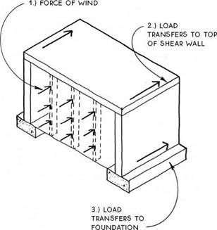
The following diagram summarizes how diaphragms and shear walls work together to resist lateral forces. For simplicity, the diagram shows a wind acting in a single direction perpendicular to the building wall, but in reality, the direction of lateral forces cannot be pre-

SINGLE-WALL CONSTRUCTION

dicted, so lateral resisting systems must be designed for the eventuality of forces in all directions.

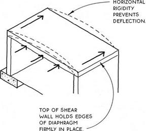
The lateral force follows a continuous path through the structure: (1) the force of wind on the windward wall is transferred through studs to the top (and base) of the wall, (2) the diaphragm collects the loads from the top of the windward wall and transfers them to the top of the shear walls at either side, and (3) the shear walls at opposite ends of the diaphragm transfer the loads down to the foundation.

The diagrams on these pages use wind forces to illus­trate how lateral forces follow a continuous path through diaphragm and shear walls. Although these structural elements are designed essentially the same to resist the forces of wind or earthquakes, these two forces act dif­ferently on buildings. Simply stated, wind forces act on the top of a building and earthquake forces act on the bottom. The relatively light weight of wood-frame build­ings works to their advantage in the case of earthquakes, but works against them in the case of high winds.

Diaphragm—A diaphragm is a horizontal structure such as a floor or roof composed of sheathing, framing members, and a structural perimeter. In the case of a floor, the framing members are joists, and the structural perimeter is composed of rim joists and/or blocking (see 32). In the case of a roof, the framing members are common rafters (or trusses), and the structural perim­eter is composed of end rafters (or trusses) and frieze blocks (see 129). A diaphragm acts as a horizontal beam to collect lateral forces and transfer these forces to the shear walls.

SINGLE-WALL CONSTRUCTION

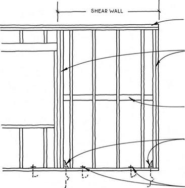
Shear walls—Shear walls are extremely strong framed walls that connect the horizontal diaphragm to the foundation. They act like regular braced or structurally sheathed walls to resist the action of lat­eral forces except that they are much stronger. Their greater strength comes from increased nailing, thicker sheathing, more framing members at their edges, and more substantial anchoring.

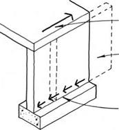
Shear walls act as beams cantilevered from the foun­dation (or upper floor) to resist forces parallel to them. They are connected at their base to the foundation (or to another shear wall) and at their top to a diaphragm.

At their base, shear walls must resist both sliding and overturning. Horizontal forces can slide the wall off the foundation if adequate shear connections are not provided. Sliding forces are resisted by anchor bolts, by nailing, and/or by framing anchors at upper floors (see 85).

SINGLE-WALL CONSTRUCTION

LATERAL FORCES FROM DIAPHRAGM

DEFLECTED SHAPE

ANCHOR BOLTS, FRAMING ANCHORS, AND/OR NAILING PREVENT SLIDING

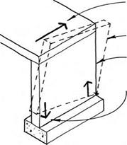
Horizontal forces applied to the top of a shear wall can cause overturning unless the bottom corners are adequately tied (with hold-downs) to resist uplift (see 85 & 86A). While the force is applied, one edge

SINGLE-WALL CONSTRUCTION

LATERAL FORCES FROM DIAPHRAGM

DEFLECTED SHAPE

LEEWARD EDGE UNDER COMPRESSION

HOLD-DOWN ANCHOI TO FOUNDATION COUNTERACTS TENSION ON WINDWARD EDGE TO PREVENT OVERTURNING.

of the wall will be in tension while the opposite edge is in compression.

Longer shear walls are inherently better because they have a longer base to resist sliding and because the hold-downs are farther apart to resist overturning.

Connections—Because shear walls involve a large number and variety of components and connec­tions, it is critical that each connection be designed and constructed to resist the forces that pass through it. Depending on their location, connections may be called upon to resist vertical and horizontal forces in several directions. When designing and building to resist extreme conditions, it is especially important to pay close attention to manufacturers’ instructions for the installation of connectors. A shear wall is only as strong as its weakest connection.

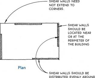
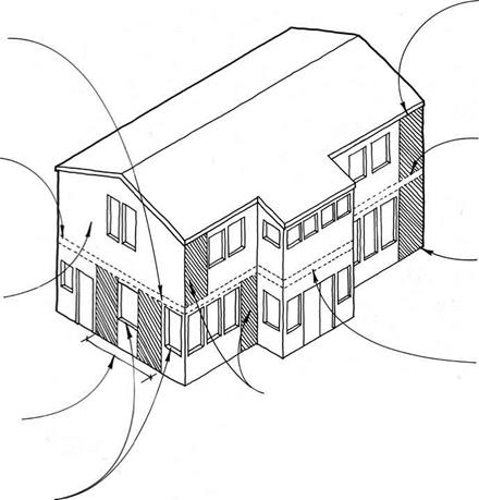
Distribution—Shear walls are generally located within each (principal) exterior wall of a building, but may also be located strategically at interior walls. For earthquake resistance, shear walls should generally be balanced on all four sides of the building; for wind resistance, however, shear walls should be longer (or stronger, see 85B) at the short walls in order to resist the larger wind forces imposed on the long walls.

SINGLE-WALL CONSTRUCTION

THE BUILDING’S PERIMETER.

SHEAR WALLS CONNECT TO FLOOR DIAPHRAGM. SEE 86B

Подпись: NOTE FOR GARAGE PORTAL FRAME, SEE 87C. Подпись:Подпись: OPENINGS IN WALL LIMIT SHEAR WALL LOCATION AND SizEПодпись:Подпись:Подпись:Подпись:Подпись:SINGLE-WALL CONSTRUCTIONDRAG strut TIEs

shear wall TO diaphragm.

SEE 87b

LARGE WALLS On upper levels MAY uSE STANDARD

code-prescribed

SHEATHING TO provide LATERAL RESISTANCE.

Because lateral forces such as wind are assumed to act perpendicularly to the walls of a building, they can theoretically be resisted by shear walls in each of the four walls of a simple building. Forces acting in a north-south direction, for example, can be resisted by shear walls located in the east and west walls of the building (and vice versa). When the wind blows on a diagonal (as it usually does), shear walls in all four walls will be in play.

Because they connect diaphragm to the foundation, shear walls cannot be placed where there are openings in the wall. Therefore, in walls with many openings, there may need to be several shear wall segments in order to provide ample resistance to lateral forces.

Shear walls are most effective when they are wide relative to their height and their base anchors are far
apart. For this reason, codes have specified that shear walls must have a height-to-width ratio of 3.5:1 or less. The practical effect of this limitation is a mini­mum shear wall width of approximately 2 ft. for a wall 8 ft. tall.

In a building with more than one floor, the need for shear walls is greater on floors nearest the ground. This is because the lower floors are required to resist the forces from upper floors in addition to their own. It is not unusual to have a two-stoiy wood-frame building with engineered shear walls on the ground floor and standard code-prescribed sheathing on the upper floor.

The calculation of shear wall values is fairly com­plicated—involving different factors for earthquake or wind forces—and is thus usually performed by a licensed engineer.

DOUBLE TOP PLATE ACTS AS A STRUT.


DOUBLE STUDS AT EDGES ACT AS CHORDS THAT STIFFEN EDGE AND PROVIDE THICK ANCHORAGE FOR HOLD-DOWNS AT Base.


blocking as required prevents buckling of PANEL EDGES.


HOLD-DOwNS AT BASE CONNECT TO FOuNDATION OR OTHER SHEAR wALLS

to prevent overturning.


ANCHOR BOLTS PREvENT SLIDING.


SINGLE-WALL CONSTRUCTION

(g) COMPONENTS OF A SHEAR WALL

SINGLE-WALL CONSTRUCTION

Once the lateral forces have been determined, there are seven basic considerations that need to be taken into account when designing a shear wall:

Proportion— Most codes specify a maximum height-to-width ratio of 3.5:1. This generally means that shear walls cannot be less than 2 ft. wide.

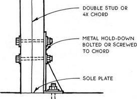
Hold-downs— Extreme forces at the lower corners of shear walls necessitate metal hold­downs to connect the shear-wall chord to the founda­tion or to lower shear walls (see 85A & 86A). There are a variety of types and capacities of hold-downs.

Anchor bolts— To prevent sliding, anchor bolts are used to connect the base of a shear wall to the foundation. At framed floors, framing anchors and nailing are used to prevent sliding. Hold-downs also resist sliding but are not generally considered in engineering calculations.

Sheathing Strength – The strength of the rated sheathing must match the required capacity of the shear wall. Sheathing on both sides of the shear wall will double its capacity. All panel edges must be blocked to prevent buckling of the panel.

Chord Strength—At the boundaries of the shear wall where stress is greatest, chords must be stronger than standard studs. A minimum of two studs is required by most codes (see 85A).

Strut Strength— Like chords, stmts are at the boundary of shear walls where stresses are greatest. Typical framing (i. e., single sole plate and double top plate) is usually sufficient as struts. Splices in struts should be avoided if possible.

Nailing—Size and spacing of nails must be specified. More nailing is required at the edges of panels than in the field of the panel. Increased nailing acts to increase wall strength (see 78A).

About the drawings

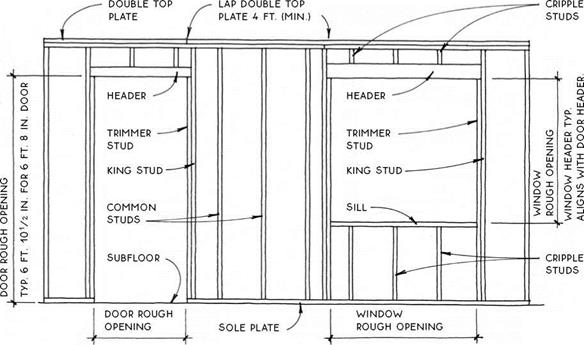
Construction terms vary regionally, and the names for the components that frame wall openings (see 68A) are the least cast in stone. Studs called “trimmer studs” in one locality are called “jack studs” in another; and the bottom plate may go by either “bottom plate” or “sole plate.” Consult local builders and architects for common usage.

For clarity, insulation is not generally shown in the exterior walls except in the insulation section (120-125).

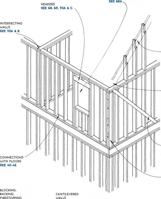
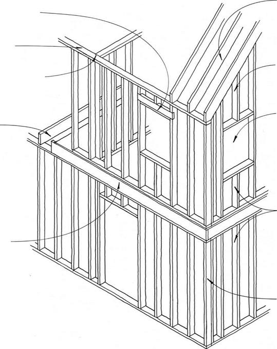
OPENINGS


RAKE WALLS SEE 72


CONNECTIONS WITH ROOF & CEILING SEE 132-134


LATERAL

bracing SEE 77


corners SEE 70A & D, 71


SEE 73A & В


SEE 73c & D


About the drawings

resource-efficient advanced framing

SEE 74 NOTE

IN THIS cHAPTER ALL 2×4 wALLS ARE SHOwN with studs AT 16 IN. O. c.; ALL 2×6 wALLS ARE shown with studs at 24 in. o. c..- unlabeled walls МАУ be EITHER 2X4 OR 2X6.

@ WALL FRAMING

About the drawings

OPENINGS IN A STUD WALL

About the drawings

& PROVIDES NAILING AT ALL SURFACES.


About the drawings

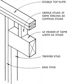
Подпись: 4X HEADERTYPICAL DOUBLE 2X HEADER

2×4 Bearing Wall


2×4 Bearing Wall


Подпись: DOUBLE TOP PLATEПодпись:Подпись: TRIMMER STUDПодпись: KING STUDAbout the drawingsDOUBLE (OR SINGLE) 2X10 HEADER WITH 2X4 SCABBED To Bottom

(eliminates the need for cripple studs in

Подпись:Подпись:Подпись:Подпись: TRIMMER STUDПодпись:Подпись:About the drawingsAN 8-FT. WALL)

About the drawings

2X10 HEADER

2×4 Bearing Wall


DOUBLE LVL OR LSL HEADER

2×4 Bearing Wall


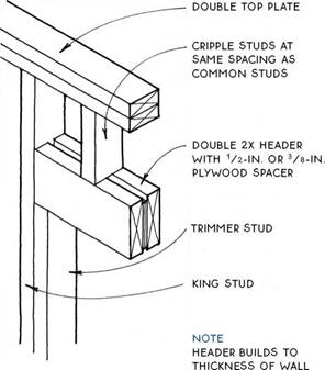
Подпись: DOUBLE TOP PLATEПодпись: CRIPPLE STUDS AT SAME SPACING AS COMMON Подпись: DoUBLE FLAT 2X4 HEADERПодпись: TRIMMER STUDПодпись: KING STUDAbout the drawingsПодпись:Подпись:Подпись:About the drawingsCRIPPLE STUDS AT SAME SPACING AS common STUDS

1/2-in. cdx plywood

Подпись:
(MIN.) NAILED To oNE SIDE oF FRAMING WITH 8D CoMMoN NAILS AT 3 IN. o. C. STAGGERED 1/2 IN. To AVoiD SPLITTING FRAMING

About the drawings

OPEN-BOX PLYWOOD HEADER

2×4 Bearing Wall


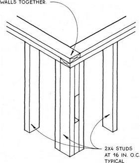
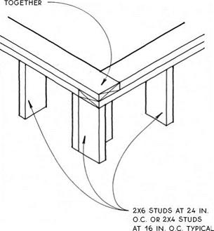
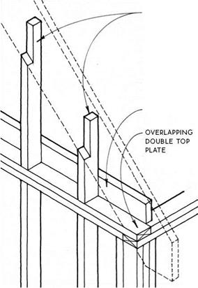
DOuBLE TOP PLATE OvERLAPs at corners to lock two


DOUBLE TOP PLATE


NOTCH CRIPPLE STUDS FOR 2X HEADER.


2X HEADER AT OUTSIDE OF WALL


2-IN. OR 4-IN. SPACE at inside of HEADER for insulation


About the drawings

KING stud


2X4 CORNER


INSULATED HEADER

2×4 or 2×6 Exterior Wall


At Double Top Plate


About the drawingsAbout the drawingsAbout the drawings

About the drawings

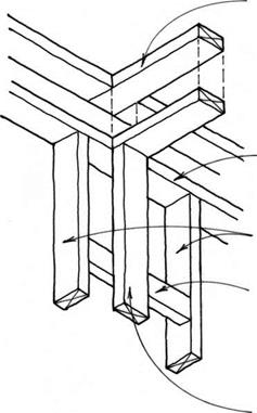
corner studs built up with 2X4 blocking BETWEEN provides nailing at

About the drawings About the drawings

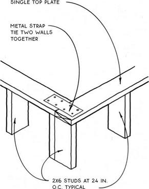
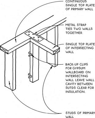
Подпись:About the drawingsПодпись: CONTINUOUS TOP PLATE OF PRIMARY WALL Подпись: COMMON STUDS IN PRIMARY WALL Подпись:Подпись:About the drawingsTOP PLATE OF INTERSECTING WALL OVERLAPS CONTINUOUS TOP PLATE OF PRIMARY WALL.

About the drawings

2X4 OR 2X6 CORNER

At Double Top Plate


INTERSECTING 2X WALLS

At Double Top Plate


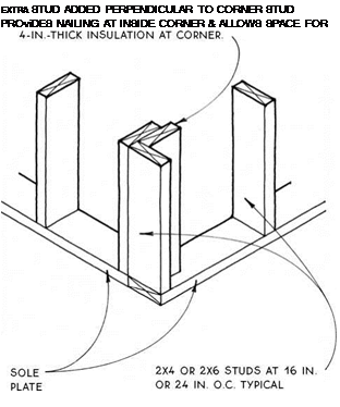
Подпись: EXTRA STUD ADDED PERPENDICULAR TO CORNER STUD PROviDES NAILING AT INSIDE CORNER & ALLOWS SPACE FOR Подпись: CONTINUOUS TOP PLATE OF PRIMARY WALLПодпись:About the drawings

NAILING AND ALLOWS SPACE FOR INSULATION

TOP PLATE OF INTERSECTING WALL OvERLAPS CONTINUOUS TOP PLATE OF PRIMARY WALL

END STUD OF INTERSECTION WALL

About the drawings

INTERSECTING 2X WALLS

At Double Top Plate/Alternative Detail


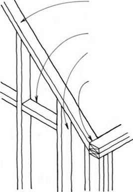
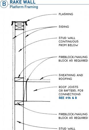
A wall that extends to a sloped roof or ceiling is called a rake wall and may be built one of two ways:

Platform framing—Platform framing is commonly the method of choice when a horizontal structural element such as a floor or ceiling ties the structure together at the level of the top plate or when the top plate itself is short enough to provide the necessary lateral strength (see 72B).

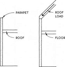
Balloon framing—Balloon framing allows for ease of construction and economy of material and stabilizes a tall wall because the studs are continuous from sole plate to roof (see 72C). Balloon framing can also be employed to stiffen a wall that projects above the roof such as a parapet or railing (see 72D). Balloon framing is greatly preferred in general from a structural per­spective where lateral forces are extreme, such as in high-wind areas.

Подпись:Подпись: CEILING JOISTAbout the drawingsFor details of rake walls with truss-framed roofs, see 156.

A RAKE wall


Notes


SINGLE TOP PLATE SLOPED TO MATCH PITCH OF ROOF


FIREBLOCKING AS REQUIRED


STUD CONTINUOUS FROM SOLE PLATE


TOP SURFACE OF SLOPED TOP PLATE FLUSH WITH INSIDE CORNER OF Double TOP PLATE


NOTE

TIE CORNER

together

with

SHEATHING OR Metal STRAPS.


About the drawings About the drawings

About the drawingsAbout the drawings

Подпись:About the drawingsПодпись: BLOCKING SUPPORTS PIPING & OTHER UTILITIES WITHIN THE WALL CAVITY. IT PROVIDES A SOLID NAILING SURFACE FOR cHANGES IN MATERIAL SUCH AS WAINSCOTING & IT ALSO SUPPORTS CABINETS, PLUMBING FIXTURES, TRIM, TOWEL BARS, BALUSTRADES & oTHER ACCESSORIES THAT ARE ATTACHED TO THE FINSH SURFACE OF THE WALL. WHEN POSSIBLE, BLocKING IS APPLIED FLAT To ALLoW INSULATION AT EXTERIOR WALLS.

About the drawings

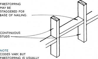
Подпись: NOTCHING BASE OF 2x6 WALL ALLOWS ELECTRICAL WIRES TO RUN WITHOUT COMPRESSING INSULATION AT CENTER OF WALL (NOT ALLOWED IN 2x4 WALL).About the drawingsrequired AT STAIRS alongside THE STRINGERS; BETWEEN floors & BETWEEN THE TOP FLooR & THE attic IN BALLooN-FRAME buildings (THE PLATES IN platform-frame buildings automatically provide fireblocking BETWEEN floors); between wall cavities & concealed horizontal spaces such as soffits & drop cEILINGS; in tall walls every 10 ft. vertically.

firestopping IS usually 2x FRAMING LuMBER but can also be other materials such as LAYERS of plywood or GYPSuM WALLBoARD WHEN approved BY LocAL coDES.

Подпись: FIRESTOPPING(д) BLOCKING & NOTCHING

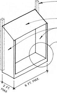
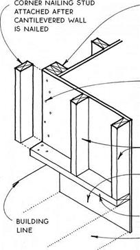
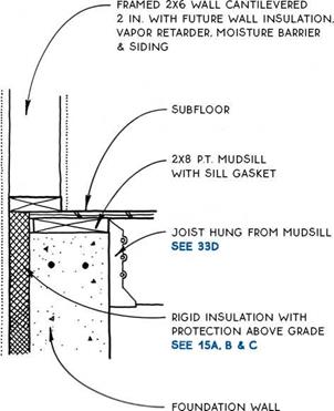
it is occasionally difficult or impossible to cantilever the floor framing to support a projection from the building. where loads are not great, it is possible to support the projection with cantilevered walls.


doubled studs at opening in primary WALL; 16D toenails or metal framing ANGLES advisable at top & bottom


double studs at opening in primary

WALL


cantilevered WALL IS supported BY NAILING

through plywood to doubled studs

IN PRIMARY WALL.


roof


cantilevered plywood walls


studs of

cantilevered wall

extend sheathing down to lap floor-system

FRAMING.

sole plate of cantilevered wall

floor-system

FRAMING


FRAMING DETAIL SEE 73D


note

cantilevered WALLS should BE ENGINEERED IF THEY

project more than

2 FT., IF THEY ARE more THAN 6 FT. APART or IF THEY WILL support heavy snow loads.


CANTILEVERED WALLS


About the drawings

About the drawingsAbout the drawings

About the drawings

roof structure

ALIGNED ovER

studs allows for single top

PLATE


REDUCED FRAMING IN STRUCTURAL HEADERS WHERE THEY ARE REQUIRED SEE 76


SINGLE TOP PLATE


balloon-framed

RAKE WALLS SEE 720


intersecting walls see 75B & D


joists aligned over studs allows for single top

PLATE


ELIMINATE

structural

HEADERS AT

openings

WHERE THEY ARE

not required


studs ALIGNED BETWEEN FLooRS


rim joist used as header

ELIMINATING

structural

HEADERS IN

openings below


superinsulated

corner

SEE 75A & c


STANDARD WALL FRAMING SEE 67


About the drawings

Advanced framing—Advanced framing minimizes the amount of framing that extends from the interior to the exterior of a wall, thus lowering the effect of thermal bridging. By limiting the amount of framing, more volume in the wall can be occupied by insulation, which increases thermal performance of the overall assembly. Advanced framing alone can increase the thermal performance of framed walls by only about
7%, but, given that it uses less material than standard framing and also helps to conserve a precious resource, it should be considered for eveiy framed building. Details of advanced framing are illustrated on 75-76. The goal when designing an energy-efficient header is to allow for the most insulation while providing for nailing at both the exterior and interior of the opening.

) ADVANCED WALL FRAMING

SUPERINSULATED 2X6 CORNER

Outside Corner Only at Top Plate


INTERSECTING 2X WALLS

At Top Plate


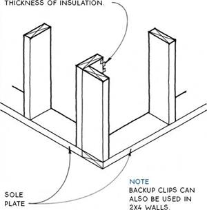
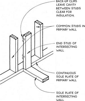
BACKUP CLIPS AT INSIDE CORNERS OF GYPSUM WALLBOARD ELIMINATE NEED FOR EXTRA STUD, ALLOWING FOR FULL

About the drawings


SUPERINSULATED 2X6 CORNER

Outside Corner Only at Sole Plate


INTERSECTING 2X WALLS

At Sole Plate


About the drawingsAbout the drawingsAbout the drawingsAbout the drawings

About the drawings

About the drawings

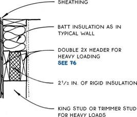
SHEATHING


ВАТТ INSULATION FOR TYPICAL WALL COMPRESED AGAINST HEADER


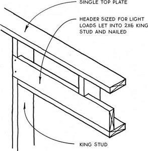
2X HEADER ADEQUATE FOR Most oPENINGs

see 760


king STUD


About the drawings

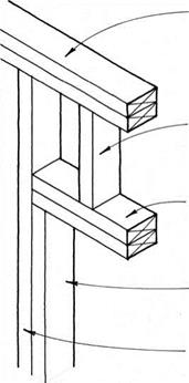
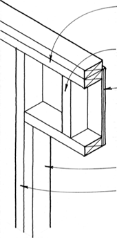
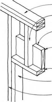
When a structural header is required over an opening in an exterior wall, the header itself occupies space that could otherwise be filled with insulation. Because a deep (tall) header is more effective structur­ally than a wide one, the header does not usually have to fill the entire width of the wall. In fact, the taller and thinner the header, the more space there will be for insulation. The headers illustrated on this page provide both structure and space for insulation. The box header

(see 69D) also provides space for insulation because it uses sheathing as structure.

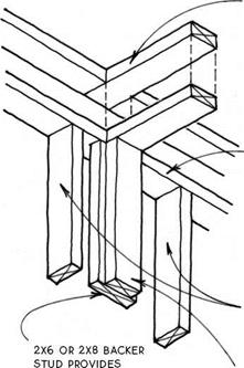
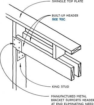
The elimination of the trimmer studs that usually support a header at its ends also allows for more insula­tion in the wall. The header can usually be supported by the king stud as illustrated in the two examples below. (Backing may need to be added to the king studs when wide casings are used.)

About the drawingsSUPERINSULATED HEADERS

General

About the drawings

FOR TRIMMER STUD.


About the drawings About the drawings

About the drawings

About the drawingsПодпись:

Most wood buildings are sheathed with plywood, OSB, or other structural panels that provide the neces­sary lateral stability when fastened directly to the stud frame (see 78-80). Where lateral forces on walls are extreme, such as in areas subject to hurricanes or earth­quakes, specially designed shear walls are commonly required to withstand these forces (see 82-87).

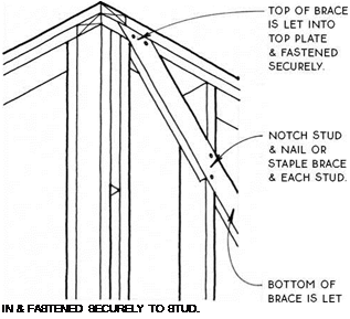
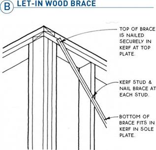
When neither structural panels nor shear walls are required, there are two good methods of bracing the building for lateral stability: the let-in wood brace (see 77B) and the kerfed-in metal brace (see 77C).

The old-fashioned method of bracing with diagonal blocking between studs is not recommended because the nails may withdraw under tension and the many joints tend to open up as the blocking shrinks.

Bracing is often referred to as “corner bracing,” and indeed, the International Residential Code begins its discussion of every allowed wall bracing method with the phrase “located at each end…” While it is true that the corners are the most effective location for a limited amount of wall bracing, it is also possible to success­fully brace a building at locations other than the cor­ners. If this were not true, there would be no corner windows. Braces may be located anywhere along a wall, and the bracing effect will be transferred to the rest of the wall through the continuous top and bottom plates. Increased nailing, stronger sheathing, and other methods can also augment bracing. A good structural engineer will be able to design walls of just about any configuration to resist lateral forces.

The methods shown here are located at a corner only for clarity of illustration.

LATERAL BRACING

Notes

NOTE

LET-IN BRACES SHOULD BE MADE OF STRUCTURALLY SOUND 1X4 OR 1X6 LUMBER. THEY SHOULD BE FROM TOP Plate TO SOLE Plate & 45° TO 60°

FROM THE HORIZONTAL.

About the drawings

NOTE

METAL BRACING SET IN A SAW KERF & NAILED TO EACH STUD IS ENGINEERED TO EQUAL THE CODE REQUIREMENTS OF A 1X4 WOOD LET-IN BRACE. SURFACE MOUNTED TYPES (WITHOUT KERF) MUST BE INSTALLED IN OPPOSING DIRECTIONS IN AN "X" OR "V" CONFIGURATION. ALL TYPES MUST BE INSTALLED AT 45° TO 60° FROM THE HORIZONTAL.

KERFED-IN METAL BRACE


About the drawings

Подпись: Notes

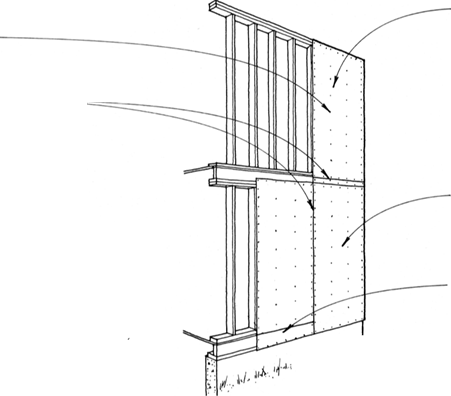
Structural sheathing performs two functions—it pro­vides lateral bracing, and it forms a structural backing for siding materials. OSB is currently the most common structural sheathing, but the use of plywood, gypsum board (which also contributes fire resistance) and other panel products is also widespread. OSB and plywood both have a strength axis along the length of the panel because of the orientation of wood fibers, but this axis

is only important in relation to its bending strength between studs. The panel’s shear strength—its ability to resist lateral forces—is not affected by its orientation.

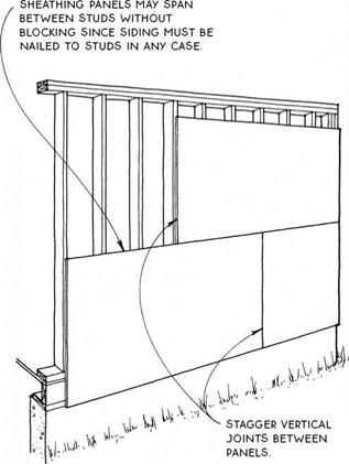
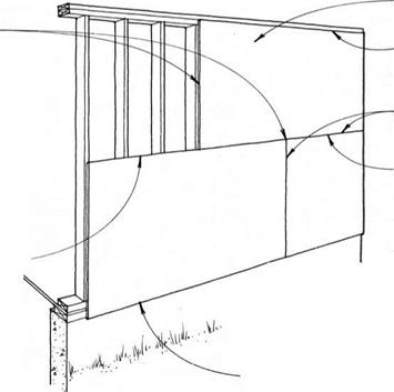
Panels may be installed either vertically or hori­zontally. Vertically applied sheathing does not usually require blocking because all panel edges are aligned with framing members. Horizontally applied panels, if engineered to provide lateral resistance, must have blocking between studs for nailing. Horizontal OSB and plywood panels provide a stronger backing for siding than do panels with a vertical orientation.

дSTRUCTURAL SHEATHING_________

In earthquake or hurricane zones or where walls are very tall or penetrated by many openings, structural sheathing may require engineering, or shear walls (see 82) may be required.

The capacity of panel products such as OSB and ply­wood to span between studs is related to thickness. The following chart applies generally:

r STUD SPACING

PANEL THICKNESS 1

16 in. o. c.

3/8 in.

24 in. o. c.

У2 in.

Nails or other approved fasteners should be sized and spaced according to the following schedule. Verify with manufacturer and local codes.

PANEL

THICKNESS

NAIL

SIZE

PANEL EDGE NAILING

FIELD

NAILING

У2 in. or less

6d

6 in. o. c.

12 in. o. c.

over У2in.

8d

PANEL NAILNG
SCHEDULE

SEE 78A


8-FT. oR 9-FT. PANEL on

second story, depending on CEILING HEIGHT


1/8-IN. SPACING BETWEEN ALL PANEL EDGES –


9-FT. PANEL LAPS RIM joiST & TIES FRAMING To foundation IN HIGH-WIND or earthquake regions.


NOTE

IN CERTAIN CASES, SUCH AS WHEN MOST OF A WALL

is covered with doors & windows, structural sheathing must be professionally engineered

AS BRACING. TYPE of SHEATHING SizE & SPACING oF NAILS

and/or tie-downs should

BE SPECIFIED.


alternative 8-FT. panel

WITH FILLER STRIP AT RIM joiST.


, >№


About the drawings

About the drawings

NOTE

IN REGIONS NOT SUBJECT TO HIGH RISK OF HURRICANE OR EARTHQUAKE, HORIZONTAL PANELS

without blocking & with filler strips at base MAY BE acceptable.

About the drawingsSTRUCTURAL SHEATHING/SINGLE-STORY BUILDING

Подпись:Подпись: L i- h •Подпись: ^ ‘Подпись:About the drawingsПодпись:Подпись:

Подпись: PANEL NAILING ScHEDULE SEE 78A UPPER EDGE OF PANEL ALIGNS WITH LOWER TOP PLATE. LEAVE 1/8-IN. SPAcE AT ALL PANEL EDGES.
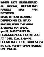
Подпись: WHEN NOT ENGINEERED AS BRACING, SHEATHING PANELS MAY PAN BETWEEN STUDS WITHOUT BLOCKING DEPENDING ON STUD SPACING, PANEL THICKNESS & SIDING MATERIAL. 3/8-IN. SHEATHING IS REcOMMENDED FOR STUDS AT 16 IN. O.c. & 1/2-IN. SHEATHING FOR STUDS AT 24 IN. O.c. VERIFY SPAN RATING ON PANELS.
Подпись: BLOCKING BEHIND PANEL JOINTS IS REQUIRED WHEN HORIZONTAL PANELS ARE ENGINEERED FOR LATERAL BRAciNG.
Подпись: NOTE: THIS DETAIL IS APPROPRIATE ONLY IF STUDS ARE PREcUT AT 903/4 IN. OR LESS & THE SUBFLOOR SITS DIRECTLY ON THE MUDSILL, SEE 33c & D, OR IF A SLAB FOUNDATION IS USED, SEE 22
Подпись: NOTE HORIZONTAL PANELS SHOWN IN THIS DETAIL MAY BE REPLAcED WITH VERTICAL PANELS. SEE 79A

Distance from Mudsill to Top Plate over 8 Ft.

STRUCTURAL SHEATHING/SINGLE-STORY BUILDING

Distance from Mudsill to Top Plate 8 Ft. or Less

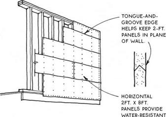
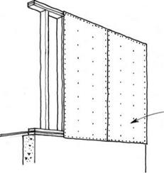
In single-wall construction, a single panel of plywood or composite board siding provides both structural and weathering functions. This is an inex­pensive, low-quality type of construction most appropriate for garages and sheds, but also used for residential construction. Panels are installed vertically, usually over a moisture barrier.

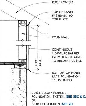
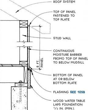
Подпись:Подпись: SINGLE-PANEL SIDING Подпись: CORNER SEE 112Подпись: BASE DETAILS SEE 80B & CAbout the drawingsПодпись: STUD WALLPrecut studs (from 88Уз in. to 92% in.) allow 8 – ft. panels to cover the framing on the exterior if the subfloor sits directly on the mudsill (see SOB) or if there is a slab floor. Adding trim to the base allows the use of 8 – ft. panels with taller studs and/or different subfloor connections (see 80C).

Taller (9-ft. and 10-ft.) panels are also available.

About the drawings

Designing a wall system

Once the stud size and spacing and the framing system have been selected, it is time to consider how to brace the building to resist the forces of wind, earthquakes, and eccentric loading. Will diagonal bracing be ade­quate, or should the building be braced with structural sheathing and/or shear walls? This question is best answered in the context of the design of the building as a whole, considering the other materials that complete the wall system. How is the wall to be insulated? Where are the openings in the wall for doors and windows? Will there be an air-infiltration barrier? What material will be used for the exterior finish? The details relating to these issues are addressed in this chapter, along with some suggestions for their appropriate use. How these various details are assembled into a complete wall system depends on local climate, codes, tradition, and the talent of the designer.

sizing headers

Headers are structural members over openings in walls for windows or doors. Header size depends on wood species and grade, loading, header design, and rough­opening span. Following is a rule of thumb for sizing a common header type, the 4x header (see 68B):

For a single-story building with a 30-lb. live load on the roof and 2×4 bearing walls, the span in feet of the rough opening should equal the depth (nominal) in inches of a 4x header. For example, openings up to 4 ft. wide require a 4×4 header and up to 6 ft. wide, a 4×6 header.

advanced framing

Advanced framing minimizes the amount of structural material that is required to hold up the building. The greatest impact on framing efficiency can be made in the walls because wall construction has evolved in such a way that the typical wall is overbuilt. Floors and roofs are constructed reasonably efficiently because the design challenge has been to span horizontally with an economy of materials. Standard framed walls, however, contain numerous extraneous and oversized elements. The elimination and downsizing of wall members not only saves lumber, it also lowers the effect of thermal bridging, thus saving energy. Advanced framing of walls is discussed in this chapter (see 74-76).

Wall

T

he walls of a building serve several important functions: They define the spaces within the building to provide privacy and zoning, and they enclose the building itself, keeping the weather out and the heat or cold in. Walls provide the vertical structure that supports the upper floors and roof of the building, and the lateral structure that stiffens the building. Walls also encase the mechanical systems (electrical wiring, plumbing, and heating). To incorpo­rate all of this within a 4-in. or 6-in.-deep wood-framed panel is quite an achievement, so numerous decisions need to be made in the course of designing a wall system for a wood-frame building. There are two pre­liminary decisions to make that establish the framework for the remaining decisions.

wall thickness

Should the walls be framed with 2x4s or 2x6s? The 2×6 wall has become increasingly popular in recent years, primarily because it provides more space for insulation and allows for other minor energy-saving advantages (such as the ability to run electricity in a notched base, as shown in 73A). These advantages all come at some cost. A 2×6 wall with studs spaced 24 in. o. c. (the maximum spacing allowed by codes) uses about 20% more material for studs and plates than a 2×4 wall with studs with a code-allowed spacing of 16 in. o. c. On the outside, the sheathing has to be V2 in. thick (Tbs in. thicker than sheathing on a stan­dard 2×4 wall). Inside, the drywall also has to be Vs in. thicker to span the 24-in. spacing between 2×6 studs. Thicker insulation costs more too. So, overall, 2×6 framing makes a superior wall, but one that costs more. Framing the exterior walls with 2x6s and interior walls
with 2x4s is a typical combination when the energy – efficient 2×6 wall is selected. Stud spacing of 2×4 and 2×6 walls may vary with loading, lumber grades, and finish materials; in this book, however, studs are assumed to be 16 in. o. c. in 2×4 walls and 24 in. o. c. in 2×6 walls unless noted otherwise.

framing style

Should the walls be built using platform framing or balloon framing? Balloon framing, with studs continuous from mudsill to top plate and continuous between floors, was developed in the 1s40s and is the antecedent of the framed wall. In recent years, balloon framing has been almost completely superseded by the more labor-efficient and fire-resistant platform frame construction, with studs extending only between floors. There are still situations, however, where a variation of the balloon frame system is useful. One such situation is where the continuity of studs longer than the normal ceiling height is essential to the strength of a wall. Examples include parapet walls and eave (side) walls

Wall

WALLS

that must resist the lateral thrust of a vaulted roof (as in a i^-story building).

Balloon-framed gable-end walls also provide increased stability in high-wind areas (see 160).

Another reason for using balloon framing is to mini­mize the effects of shrinkage that occurs across the grain of joists in a platform-framed building. This could be important with continuous stucco siding that spans two floors without a control joint, or in a multiple-story hybrid building system where the floors in the balloon­framed part would not shrink equally with the floors in the platform-framed part.

FLOOR INSULATION

FRAMED WALL WiTH FUTURE WALL iNSULATiON, VAPOR RETARDER, MOiSTURE BARRiER & SiDiNG

SUBFLOOR


vapor retarder on top of subfloor can be SEALED TO wALL vApOR RETARDER AT Bottom

plate.


unfaced fiberglass-batt

iNSULATiON FILLS JOIST OR GIRDER cAviTiES.

SEE 61


p. T. MUDSILL FOUNDATION wALL


дЛ FLOOR INSULATION AT FOUNDATION /gN FLOOR INSULATION AT FOUNDATION


Uninsulated Basement or Crawl Space


Heated Basement/Joist on Mudsill


FLOOR INSULATIONFLOOR INSULATION

FLOOR INSULATION

FLOOR INSULATION

FLOOR INSULATION

NOTE

INSULATION IS NOT cONTINUOUS SO This DETAIL NOT REcOMMENDED FOR EXTREME OJMATES UNLESS wALLS ARE SUpERINSULATED.

SEE 121B

FLOOR INSULATION AT FOUNDATION

Heated Basement/Joist Flush with Mudsill

FLOOR INSULATION AT FOUNDATION

Heated Basement/Joists Flush with Mudsill

Подпись: FRAMED WALL WiTH FUTURE WALL iNSULATiON, VAPOR RETARDER, MOiSTURE BARRiER & SiDiNGПодпись: SUBFLOORПодпись: BLOCKING WHERE JOiSTS ARE pARALLEL TO WALLFLOOR INSULATIONПодпись:FLOOR INSULATION

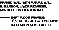
Подпись: FRAMED WALL WiTH FUTURE WALL INSULATION, vApOR RETARDER, MOiSTURE BARRiER & SiDiNG — SHIFT FLOOR FRAMING 11/2 IN. TO ALLOW FOR RIGID INSULATION AT PERIMETER.

Ватт INSULATION OR SPRAУED-iN-PLACE Foam INSULATION in cAviTiES BETwEEN JOiSTS, BLOOKING

& subfloor

place vapor retarder on

WARM SiDE OF iNSULATiON
rim joist or blocking AS

REQUIRED BY JOIST BEARING SUBFLOOR

JOIST WiTH 1V2-IN. BEARING (MIN.) OR JOIST HANGER

continuous vapor RETARDER wraps OUTSIDE FLOOR FRAMING & EXTENDS TO INTERIOR OF pLATES TO BE SEALED TO WALL vApOR RETARDER.

blocking AS REQUIRED FRAMED WALL

д) UPPER-FLOOR INSULATION

Platform Framing

UPPER-FLOOR INSULATION

Platform Frame: Alternative Detail

Подпись: VAPOR RETARDER CONTINUOUS BEHIND JOIST; SEAL TO WALL vApOR RETARDER ABOvE & BELOW.Подпись: INSULATE WALL BEHIND JOIST BEFORE JOIST IS INSTALLED.Подпись: CONTINUOUS HEADER JOIST ScREWED TO WALLFLOOR INSULATIONFLOOR INSULATION

2X4 OR 2X6 FRAMED WALL WiTH FUTURE WALL INSULATION, vApOR RETARDER, MOiSTURE BARRiER & SiDiNG

fire/nailing block

SUBFLOOR

NOTE:

because the JOiSTS do not penetrate THE WALL cAviTiY, it is possible TO provide A GOOD SEAL against air infiltration. however, this detail DOES NOT provide THE LATERAL STRUCTURAL STRENGTH OF ALTERNATivE DETAIL. SEE 63D
2X4 OR 2X6 FRAMED WALL WiTH FUTURE WALL INSULATION, vApOR RETARDER, MOiSTURE BARRiER & SiDiNG

fire/nailing blocks

SUBFLOOR

WALL cAN BE INSULATED AT TIME OF INSULATION OF WALLS ABOvE & BELOW ONLY IF NAILING BLOck IS

installed in coordination

WiTH INSULATION.

vapor retarder at warm

SiDE OF INSULATION

continuous let-in

LEDGER

NOTE:

BEcAUSE JOiSTS pERpENDicULAR TO THE WALL penetrate the wall cavity, it is difficult TO

GET A TIGHT SEAL AGAINST AIR INFILTRATION FOR ALTERNATivE DETAIL. SEE 63c

Подпись: UPPER-FLOOR INSULATION Balloon Frame: Alternative Detail UPPER-FLOOR INSULATION

Balloon Framing/Joists Perpendicular to Wall

FLOOR INSULATION

SOLID RAILING AT PORCH OR DECK

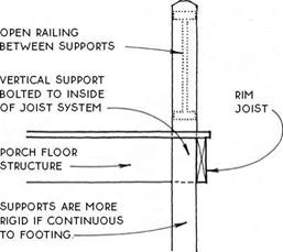
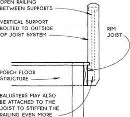
Open railings are connected to the floor of a porch or deck only intermittently, where the vertical supports occur. It is through these supports that open railings gain their rigidity. When the end of the railing is sup­ported at a wall or a column, no special connections are required. When the vertical support does not coin­cide with a rigid part of the structure, however, a rigid connection must be made with the floor system of the porch or deck. One logical place to locate this con­nection is at the inside edge of the rim joist (see the drawing below).

SOLID RAILING AT PORCH OR DECK

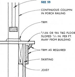
Another logical place to secure the railing to the porch floor is at the outside of the rim joist (see the drawing below). This is usually the most practical choice for waterproof decks, since the railing does not have to penetrate the waterproof surface.

SOLID RAILING AT PORCH OR DECK

However the railing is attached to the porch, its rigidity depends ultimately on the solid construction of the porch framing. Pressure-treated joists will con­tribute to the floor’s longevity, and metal hangers and clips will add rigidity. Block between joist bays when the railing is parallel to the joist system.

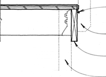
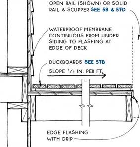
Waterproof deck with open railing—Waterproof decks surrounded by an open railing should be sloped away from the wall(s) of the building. Drainage may be distributed around all open edges, as shown below, or it can be collected in a scupper.

SOLID RAILING AT PORCH OR DECK

Open deck with open railing—Open decks sur­rounded by an open railing are relatively simple to drain. Be sure to provide adequate drainage from the surface below the deck.

(g) OPEN RAILING AT PORCH OR DECK

SOLID RAILING AT PORCH OR DECK

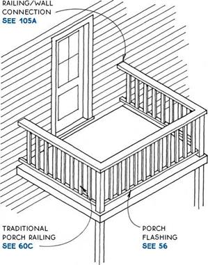
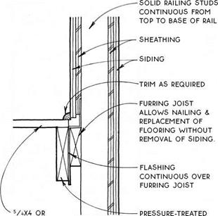
A wood porch with an open railing and a tongue – and-groove wood floor has been a tradition throughout the United States for the entire history of wood-frame construction and is still in demand. A tongue-and-groove porch floor is actually a hybrid between a waterproof deck and an open deck because although it is not water­proof, it is also not truly open like the spaced decking of open porch or deck floors. Moisture is likely to get trapped in the tongue-and-groove joint between floor boards and cause decay. To avoid this problem, the floors of these porches are often painted annually. Weather- resistant species or wood that has been pressure-treated will provide the most maintenance-free porch.

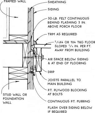
The tongue-and-groove wood porch was traditionally built without flashing. But for a longer lasting porch, the connection between the porch floor and the main structure should be flashed for the same reason as for all open porch and deck floors.

SOLID RAILING AT PORCH OR DECK

TRADITIONAL WOOD PORCH

Floor Characteristics

TRADITIONAL WOOD PORCH

Connection to Main Structure

OPEN RAiLiNG

SOLID RAILING AT PORCH OR DECK


1X4 T&G FLOOR

SLOPED

1/4 iN. PER FT.

AWAY FROM BUiLDiNG


JOiST NAiLED To FURRiNG JOiST through flashing


SOLID RAILING AT PORCH OR DECK

Подпись: TRADITIONAL WOOD PORCH Closed Railing TRADITIONAL WOOD PORCH

Open Railing

Подпись:Подпись:Подпись:Подпись:Подпись:SOLID RAILING AT PORCH OR DECKSOLID RAILING AT PORCH OR DECK

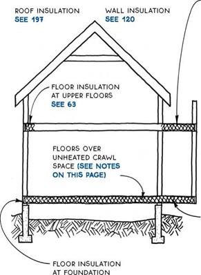
Floor insulation—Building codes in most climates require at least R-11 for floors over unheated spaces.

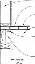
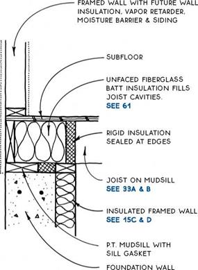
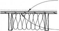
Installation—Floors over vented crawl spaces and other unheated areas are typically insulated with fiber­glass batts because the ample depth of the floor struc­ture can accommodate this cost-effective but relatively bulky type of insulation. The batts are easiest to install if weather and other considerations permit them to be dropped in from above. To support the batts, a wire or plastic mesh or wood lath can first be stapled to the underside of the joists, or plastic mesh can be draped very loosely over the joists.

SOLID RAILING AT PORCH OR DECK

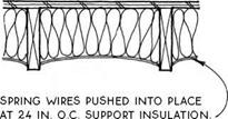
support fiberglass-batt insulation with wire or plastic mesh, or with wood lath or wire AT 12 in. o. C.

When crawl-space floor insulation must be installed from below, spring wires are cheap, easy, and effective.

SOLID RAILING AT PORCH OR DECK

Floor insulation over open areas that are exposed to varmints and house pets should be covered from below with solid sheathing (see 88A).

Vapor retarder—A vapor retarder is not always required in the floor structure over a crawl space because the temperature differential between the inte­rior space and the crawl space is not always enough to cause condensation. A floor over a heated basement or crawl space (see 8) would not require a vapor retarder. When conditions do require a vapor retarder or when an air-infiltration barrier (AVB) is desired, a 4-mil air/ vapor barrier may be placed on the warm side of the insulation, as shown in the drawing below.

vapor retarder can go on top of subfloor if unfaced batt insulation is below, or

vapor retarder can be integral with or on top side of insulation.

A vapor retarder placed on the subfloor is more con­tinuous than one on the top side of the batts, and it also will not trap rainwater during construction. Floor vapor retarders in any position are likely to accumulate mul­tiple nail penetrations and should be coordinated with the finish floor. For more on vapor retarders and air – infiltration barriers, see 120.

Perimeter insulation—Floors whose perimeter completes the thermal envelope, such as upper floors that are located over a heated space, need only be insu­lated at their perimeter, not throughout the entire floor. The continuity of insulation and air/vapor barriers at this location requires serious consideration (see 62B,

C & D and 63).

COMPOSITE FLOOR TRUSSES

COMPOSITE FLOOR TRUSSES

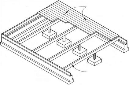
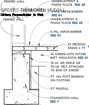
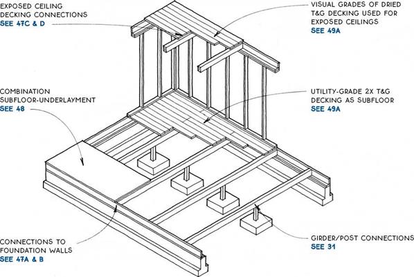
Girder systems may be designed with either dimen­sion or laminated lumber. They are most common in the Northwest, where dimension timber is plentiful. Girder floor systems are similar to joist floor systems except that girders, which are wider than joists, can carry a greater load for a given span and therefore can be spaced at wider intervals than joists. Girders are typically placed on 48-in. centers, so long-spanning subfloor materials such as 2-in. T&G decking or lVs-in. combination subfloor-underlayment are required (see 48).

When used over crawl spaces, girders may be sup­ported directly on posts. Over a basement, a girder system may be supported on posts or may bear on a wall or a beam like a joist system. At upper floor levels, girder systems are often used in conjunction with an

GIRDER SPANS

Size, species, grade, and spacing

Span (ft.)

4 x 6 Douglas-fir #2 @48 in. o. c.

8.6

4 x 8 Douglas-fir #2 @48 in. o. c.

11.3

4 x 10 Douglas-fir #2 @48 in. o. c.

14.4

4 x 12 Douglas-fir #2 @48 in. o. c.

17.6

exposed T&G decking ceiling. These exposed ceilings can make wiring, plumbing, and ductwork difficult.

This table assumes a 40-psf live load, a 10-psf dead load, and a deflection of L/360. The table is for esti­mating purposes only. No. 2 Douglas-fir is most preva­lent in regions where girder systems are most frequently used.

) GIRDER-FLOOR SYSTEMS

FRAMED WALL
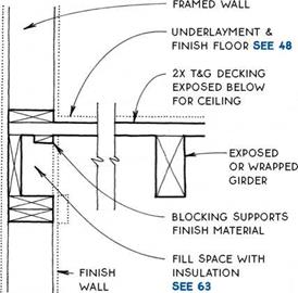
COMPOSITE FLOOR TRUSSESПодпись: NOTE DECKING DOES NOT PROVIDE STRUCTURAL DIAPHRAGM REQUIRED AT UPPER FLOORS. USE PLYWOOD UNDERLAYMENT OR OTHER METHOD TO TRANSFER LATERAL LOADS. Подпись:COMPOSITE FLOOR TRUSSES

COMPOSITE FLOOR TRUSSES

UNDERLAYMENT &

FiNiSH FLOOR SEE 48

2X T&G DECKiNG EXPOSED BELow

for ceiling

exposed or wrapped girder

blocking applied between and to sides of girders supports WALL finish.

note

Подпись: GIRDERS WITH EXPOSED DECKING 2nd Floor: Girders Perpendicular to Wall Подпись: GIRDERS WITH EXPOSED DECKING 2nd Floor: Girders Parallel to Wall

2X T&G decking may BE SANDED To МАКе FiNiSH floor, but this is advisable only with very dry decking. dust filtration from upper to lower floor & sound transmission between floors MAY occur with THIS DETAIL.

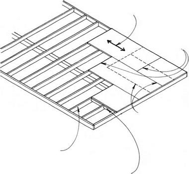
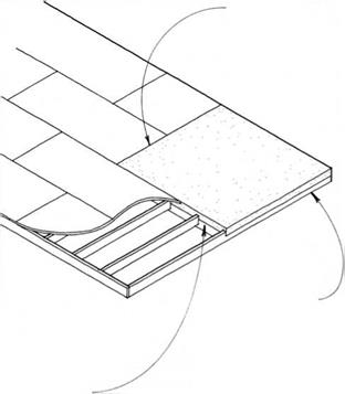
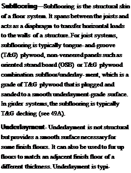
Подпись: Subflooring—Subflooring is the structural skin of a floor system. It spans between the joists and acts as a diaphragm to transfer horizontal loads to the walls of a structure. For joist systems, subflooring is typically tongue- and-groove (T&G) plywood, non-veneered panels such as oriented strand board (OSB) or T&G plywood combination subfloor/underlay- ment, which is a grade of T&G plywood that is plugged and sanded to a smooth underlayment-grade surface. In girder systems, the subflooring is typically T&G decking (see 49A). Underlayment- Underlayment is not structural but provides a smooth surface necessary for some finish floors. It can also be used to fur up floors to match an adjacent finish floor of a different thickness. Underlayment is typi- COMPOSITE FLOOR TRUSSES
Подпись: OFFSET JOiNTS OF SUBFLOOR & UNDERLAYMENT PANELS.

Подпись: Subfloor typeПодпись:

COMPOSITE FLOOR TRUSSES COMPOSITE FLOOR TRUSSES

COMPOSITE FLOOR TRUSSEScally plywood, particleboard, or hardboard.

TECHNICAL

INFORMATION

COMPOSITE FLOOR TRUSSESSUBFLOORING & UNDERLAYMENT

Plywood & Non-Veneered Panels

Typical T&G Decking Sections

Подпись:Подпись: GIRDERCOMPOSITE FLOOR TRUSSESПодпись: NOTE GLUE DECKING TO GIRDERS WITH CONSTRUCTION ADHESIVE TO MINIMIZE FLOOR SQUEAK. REFER TO WESTERN WOOD PRODUCTS USE BOOK FOR SPAN INFORMATION. 2X6 v-JOINT IS MOST.

commonly used ON

upper FLOORS TO MAKE EXpOSED

ceilings below. most species

WILL SpAN 4 FT.

2X8 uTILITY IS

used primarily as subfloor over crawl spaces

OR BASEMENTS & IS OFTEN INSTALLED GREEN. IT WILL SpAN 4 FT. IN MOST FLOOR SITuATIONS.

COMPOSITE FLOOR TRUSSES3X AND 4X LAMINATED IS uSED MOSTLY AT ROOFS TO MAKE EXpOSED cEILINGS BELOW, BuT ALSO AS FLOORING.

decking is end matched FOR random-length application & IS available pREFINISHED IN 3X6, 3X8, 4X6, & 4X8 sizes. IT SpANS up TO 14 FT. FOR RESIDENTIAL FLOOR LOADS.

COMPOSITE FLOOR TRUSSES

SUBFLOORING

T&G Decking


COMPOSITE FLOOR TRUSSESCOMPOSITE FLOOR TRUSSES

Подпись:Подпись: CONCRETE SuBFLOOR/ FOUNDATION SEE 50A, B & c
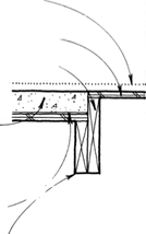
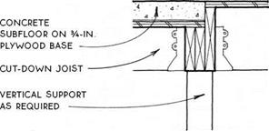
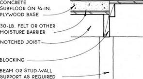
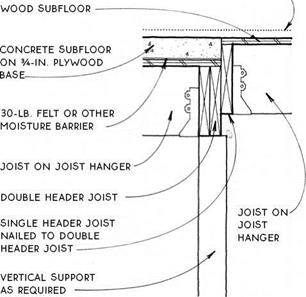
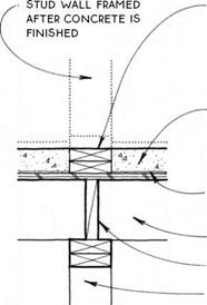
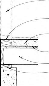
A small part of the subfloor may need to be concrete to support tiles or for a passive-solar mass floor at a south edge. The structure under the concrete must be lowered in order to accommodate the extra thickness of the concrete, typically 2Yi in. to 3 in. Use plywood that is rated to cany the load of wet concrete, usually 3/4 in. (min.).

In the case of a tiled floor, the complications of adjusting the structure to accommodate a thick con­crete subfloor may be avoided by using a Vw in. thick glass-fiber-reinforced cement board over the surface of the typical wood subfloor. Check with the tile manufac­turer for recommendations.

concrete

SuBFLOOR/HEADER

JOIST

SEE 51A & B


NOTE:

FOR THIN-MASS FLOORS SEE 510 & D


SUBFLOORING

Concrete


COMPOSITE FLOOR TRUSSES

Подпись: WOOD & FOUNDATiONПодпись: P.T. MUDSiLLCOMPOSITE FLOOR TRUSSESCOMPOSITE FLOOR TRUSSES

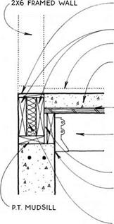
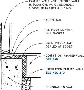
Подпись: NOTE; FOR 2X4 WALL, PLACE INSULATION BETWEEN DOUBLE RiM JOiST & P.T. HEADER JOiST.

FRAMED WALL

FURRiNG SAME THiCKNESS AS WOOD SUBFLOOR

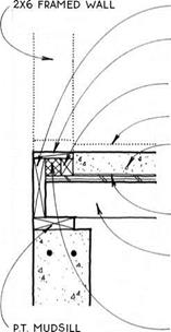
P. T. MUDSiLL

FiNiSH Floor

concrete subfloor ON

3A-iN. PLYWOOD BASE; LEVEL AND THiCKNESS VARY WiTH FiNiSH MATERiAL.

30-LB. FELT OR OTHER MOiSTURE BARRiER

iNSULATiON

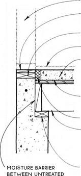
JOiSTS BEAR ON LEDGE iN FOUNDATiON WALL OR ON LEDGER OR PONY WALL SEE 12D

FURRiNG SAME THiCKNESS AS WOOD SUBFLOOR

DOUBLE RiM JOiSTS FiNiSH FLOOR

CONCRETE SUBFLOOR ON 3A-IN. PLYWOOD BASE;

LEVEL AND THiCKNESS VARY WiTH FiNiSH MATERiAL.

30-LB. FELT OR OTHER MOiSTURE BARRiER

JOiSTS HUNG FROM P. T. HEADER JOiST RiPPED TO BEAR ON FOUNDATiON WALL.

SPACER BLOCKS AT 16 iN. O. C.

MOiSTURE BARRiER BETWEEN UNTREATED JOiSTS & FOUNDATiON

insulation

COMPOSITE FLOOR TRUSSES

CONCRETE SUBFLOOR AT EXTERIOR

Full-Depth Joists below Mudsill

CONCRETE SUBFLOOR AT EXTERIOR

Full-Depth Joists/Alternative

NOTE

FOR CONDITION AT EXTERIOR WALL SEE 50A & B.


COMPOSITE FLOOR TRUSSES

RIM JOiST


FURRiNG SAME THiCKNESS AS WOOD SUBFLOOR

FURRiNG

FiNiSH FLOOR

CONCRETE SUBFLOOR ON 3A-1N. PLYWOOD BASE;

LEVEL AND THiCKNESS VARY WiTH FiNiSH MATERiAL.

30-LB. FELT OR OTHER MOiSTURE BARRiER

JOiSTS CUT OR SIZED DOWN TO ACCOMMODATE DEPTH OF CONCRETE SUBFLOOR

INSULATION


PLYWOOD OR OTHER WOOD SUBFLOOR

TYPICAL JOiSTS


COMPOSITE FLOOR TRUSSES

NOTE

DECREASE SPAN AND/OR SPACING OF SIZED-DOWN JOiSTS SUPPORTING CONCRETE.


COMPOSITE FLOOR TRUSSESCOMPOSITE FLOOR TRUSSESCOMPOSITE FLOOR TRUSSES

COMPOSITE FLOOR TRUSSES

CONCRETE SUBFLOOR AT EXTERIOR

Cut-Down Joists on Mudsill

CONCRETE SUBFLOOR AT INTERIOR

Edge Parallel to Joists/2 Details

NOTE

FOR CONDiTiON AT EXTERiOR WALL SEE 50A OR B.


FiNiSH FLOOR

COMPOSITE FLOOR TRUSSES


COMPOSITE FLOOR TRUSSES

PLYWOOD OR OTHER


FiNiSH FLOOR

COMPOSITE FLOOR TRUSSES


COMPOSITE FLOOR TRUSSES

COMPOSITE FLOOR TRUSSES

д) CONCRETE SUBFLOOR AT INTERIOR

Edge Perpendicular to Joists

CONCRETE SUBFLOOR AT INTERIOR

Edge Perpendicular to Joists: Alternative Details

Подпись: DOUBLE 2X P.T. PLATE SERVES AS SCREED & ALLOWS UTILITIES TO PASS THROUGH FLOOR SYSTEM AT WALL.Подпись: 3-IN. CONCRETE SUBFLOOR ON 3A-IN. PLYWOOD BASECOMPOSITE FLOOR TRUSSESПодпись: 30-LB. FELT OR OTHER MOISTURE BARRIER JOIST BLOCKING STRUCTURE BELOW AS REQUIRED Подпись: STUD WALL FRAMED AFTER cONcRETE iS FINISHED Подпись: DOUBLE 2X P.T. PLATE SERVES AS SCREEDПодпись: 3-IN. CONCRETE SUBFLOOR ON 3A-IN. PLYWOOD BASECOMPOSITE FLOOR TRUSSES30-LB. FELT OR OTHER MOISTURE BARRIER

JOIST

P. T. MUDSILL (OR TOP PLATE IF THIN-MASS SUBFLOOR IS AT UPPER STORY)

NOTE

THIS DETAIL IS USED TO PROVIDE MASS TO A LARGE AREA OF FLOOR FOR SOLAR GAIN.

NOTE

IF THE CONCRETE IS TO BE EXPOSED, THE DOUBLE PLATE MAY BE OMITTED FOR EASE OF TROWELING. THE STUD WALL MAY THEN BE SHOT TO CONCRETE SEE 24C

THIN-MASS SUBFLOOR

THIN-MASS SUBFLOOR

COMPOSITE FLOOR TRUSSES

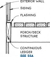
Подпись: EXTERiOR WALL _ SiDiNG SPACE ALLOWS WATER TO PASS. PORCH/DECK STRUCTURE Подпись: CONNECTORS AT iNTERVALS SEE 54B & CCOMPOSITE FLOOR TRUSSES

Porches and decks are traditional and useful addi­tions to wood-frame structures. They provide a transi­tion between indoors and out, allowing people to pause upon entering or leaving, and they extend the building to include the out-of-doors. Porch and deck floors must be constructed differently from interior floors in order to withstand the weather. The connection between porch and deck floors and the building itself is espe­cially critical in keeping moisture out of the main struc­ture. Because of constant exposure to the weather, this connection must be detailed in such a way that it can be repaired or replaced.

COMPOSITE FLOOR TRUSSES

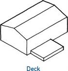
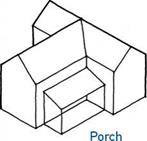
The floors of porches and decks can be grouped into two major types: those that are waterproof and thus act as a roof protecting the area below, and those that are open and allow water to pass through.

Waterproof

Porch/Deck

Floor

COMPOSITE FLOOR TRUSSES

Open

Porch/Deck

Floor

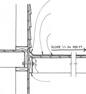
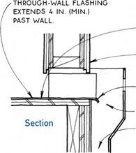
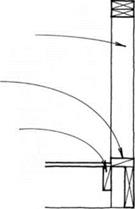
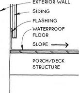
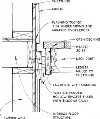
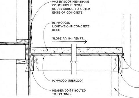
Waterproof porch—A waterproof porch or deck floor can be treated like a flat roof. As shown in the drawing below, flashing (or the roofing material itself) must be tucked under the siding to catch water running down the side of the building, and the floor (roof) sur­face must be sloped away from the building (see 56A). The framing for waterproof decks over living spaces needs proper ventilation (see 205A).

COMPOSITE FLOOR TRUSSES

Open porch—In an

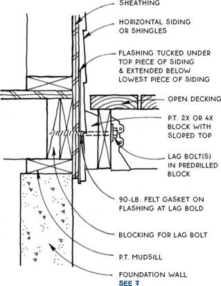
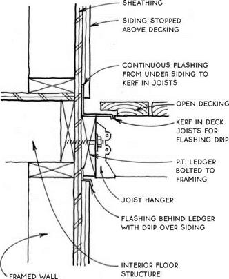
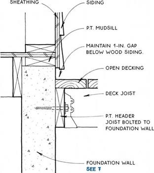
open porch or deck floor, the parts that connect it to the main structure are exposed to the weather, yet need to penetrate the skin of the wall. This connection can be accomplished by keeping the porch/ deck structure away from the exterior wall and attaching it only at intervals with spaced connectors (see 54B & C).

Alternatively, a continuous ledger may be bolted to the wall and flashed (see 55A & B).

(g) PORCHES & DECKS

COMPOSITE FLOOR TRUSSES

Porches and decks are exposed directly to the weather in ways that the main part of the structure is not. Consequently, the wood used in porches and decks is much more susceptible to expansion and contraction, twisting, checking, and rotting. A special strategy for building porches and decks is therefore appropriate.

Weather resistance – Elements of porches and decks that are likely to get wet should be constructed of weather-resistant materials. Virtually all the material required to make a new porch or deck is now available in pressure-treated lumber. Weather-resistant woods like cedar or redwood are also appropriate.

Connectors – At least once a year, joints that are exposed to the weather will shrink and swell, causing nails to withdraw and joints to weaken. Joints made with screws or bolts will therefore outlast those made with nails. For joist connections, use joist hangers or angle clips.

Joist hangers are made of galvanized steel, which should not be adversely affected by exposure to the weather. Galvanized steel deteriorates relatively quickly, however, when combined with pressure – treated lumber, especially when moisture is added to the mix. Therefore, always use connectors with the longer-lasting hot-dip galvanized finish. Also, consider the use of weather-resistant wood species for use with galvanized hangers.

Fasteners such as nails and deck screws should be galvanized. Stainless steel screws are also available and will give the longest life.

Framing—Areas between adjacent wood members collect moisture and are especially prone to rot. Even pressure-treated lumber can rot in this situation. Avoid doubling up members in exposed situations. It is better to use a single large timber where extra strength is required, as shown in the drawing at right.

Where wood must touch another surface, make the area of contact as small as possible and allow for air cir­culation around the joint.

Wood decking—Because decking is oriented horizon­tally, it has a relatively large exposed surface to collect and absorb moisture. This moisture will tend to make the decking cup. Most references suggest installing flat – grain wood decking (and rail caps) with the bark side down because boards will cup in the right direction to shed water as they season.

COMPOSITE FLOOR TRUSSES

Unseasoned (wet) Seasoned (dry) Wet

However, if dry (seasoned) decking is installed with the bark side down, the boards will cup in the wrong direction when they get wet. Therefore, dry decking boards should be installed with the bark side up so that the boards will shed water if they cup.

COMPOSITE FLOOR TRUSSES

Seasoned Wet

Synthetic decking—There is a new generation of synthetic decking made of reclaimed hardwood and recycled plastic. This material holds up in exposed con­ditions, is not harmed by rot or insects, and is extremely consistent and stable. The decking is not as stiff as sawn lumber, so it requires closer joist spacing. It can be fastened to framing with conventional methods and is available in standard sizes from 1×6 to 2×8.

Because the decking does not absorb water, thermal expansion is more of a concern than warping or cup­ping. The decking requires no sealers or preservatives and is manufactured with a nonskid surface. It is dis­posable (no toxins).

Painting—Sealers and preservatives will extend the life of porches and decks. Special attention should be given to end grain and to areas likely to hold moisture. Stains will outlast paints. Special porch and deck paints are available for use where exposure to the weather is not severe.

@ PORCH & DECK CONSTRUCTION
COMPOSITE FLOOR TRUSSESCOMPOSITE FLOOR TRUSSES

Подпись: st

(g) OPEN DECK/FOUNDATION WALL

pN OPEN DECK/WOOD WALL

Floor : Horizontal Siding or Shingles
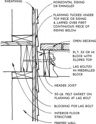
COMPOSITE FLOOR TRUSSESNOTES

FLASHiNG EXTENDS 8-iN. MiNiMUM PAST BOTH SiDES OF BLOCK SPACERS.

iNSTALL Spacer BLocKS SiMULTANEOUSLУ with SiDiNG & FLASHING, Then iNSTALL Deck.

opEN DEcKiNG LAID DiAGONALLУ AcRoSS JoiST sysTEM acts as a DiAPHRAGM, wHicH мау eliminate the need for bracing porch supports.

DETAILS show level of DEcK SLiGHTLy BELow level of FiNiSH floor. iN SNow couNTRy, adjust deck level and flashing height to account for snow buildup.

spaced decking is often used for the floor of a screened porch. in this case, the decking must be installed over insect screening.

OPEN DECK/WOOD WALL

2nd Floor: Horizontal Siding or Shingles
COMPOSITE FLOOR TRUSSESCOMPOSITE FLOOR TRUSSES

(g) OPEN DECK/WOOD WALL

OPEN DECK/WOOD WALL

Alternative Detail

OPEN RAiLiNG BOLTED TO JOiSTS OR AS EXTENSiON OF VERTiCAL SUPPORT SEE 59A


SOLID RAILING Of STuDS & SIDING SEE 55A


OPEN DEcKiNG


OPEN DECKING


DEcK JOiST

supported ву

JOiST HANGER ON HEADER JOiST


DECK JOiST SUPPORTED ВУ JOiST HANGER ON HEADER JOiST


HEADER JOiST BOLTED TO STuDS


HEADER JOIST SCREWED OR BOLTED TO VERTICAL SUPPORTS


FLASHING TucKED 1 in. under SIDING AND BEHIND HEADER JOiST


skirting


stud wall, wood

POST, OR Other

vertical support


stud WALL, WOOD POST, OR OTHER

vertical support


COMPOSITE FLOOR TRUSSESCOMPOSITE FLOOR TRUSSESCOMPOSITE FLOOR TRUSSES

OPEN DECK/OPEN RAILING

OPEN DECK/SOLID RAILING

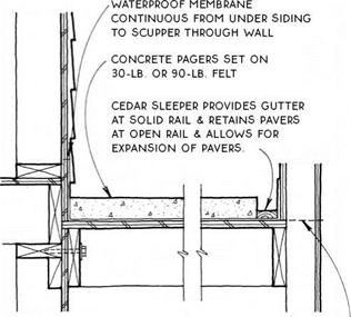
Подпись:Подпись: SLIP SHEET AS REQUIRED WITH SOME COATINGS.COMPOSITE FLOOR TRUSSESПодпись: ELASTOMERIC. BITUMINOUS. OR OTHER WATERPROOF MEMBRANE OR COATING.- EXTEND COATING FROM UNDER SIDING TO EDGE OF DECK.Подпись: HEADER JOIST BOLTED TO FRAMING MINIMIZES MOVEMENT.COMPOSITE FLOOR TRUSSESПодпись: General CharacteristicsПодпись: ДЛ WATERPROOF DECKS
NOTES

WATERPROOFiNG CAN BE PROTECTED FROM ABRASiON ВУ ADDiTiON OF WOOD OR CONCRETE-PAVER SURFACE, SEE 57A, в & C

slope may BE ACHiEvED By SLOpING JOiSTS OR,

where a level surface is required below, ву ripping joists or adding furring strips.

EDGE flashing WITH DRip extends 4 in. under waterproofing.

attachment of railings see 58 & 59

rim joist deeper than

DECK JOISTS TO FORM DRip

stud wall, WOOD post, OR other vertical support
COMPOSITE FLOOR TRUSSESNOTE

if rail is solid, slope

CONCRETE TO SCuppERS FROM ALL DIRECTIONS. see 57D

NOTE

alternative flashing detail below will provide A FORM FOR EDGE OF CONCRETE.

COMPOSITE FLOOR TRUSSES

EDGE FLASHING WITH DRip

extends 4 in. under waterproof membrane.

rim joist deeper than deck

JOISTS TO FORM DRip

stud wall, WOOD post, OR other vertical support

COMPOSITE FLOOR TRUSSES

LIGHTWEIGHT-CONCRETE PORCH DECK

COMPOSITE FLOOR TRUSSES

COMPOSITE FLOOR TRUSSES

UNDERSIDE OF SLEEPERS.


NOTE

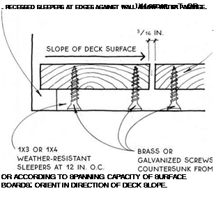
DUCKBOARD DECKS ARE GENERALLY HELD iN PLACE ВУ GRAViTY. THEY SHOULD NOT BE USED iN AREAS OF EXTREMELY HiGH WiNDS.


COMPOSITE FLOOR TRUSSES

COMPOSITE FLOOR TRUSSES

DUCKBOARD DECK

Open Rail Shown

DUCKBOARD DECK

Detail

COMPOSITE FLOOR TRUSSES

Подпись: LOW POINT IN DECK FLOOR SIDING FORMS DRIP OVER WALL OPENING Подпись: EXTEND FLASHING DRIP BEYOND SIDING SCUPPER DOWNSPOUT COMPOSITE FLOOR TRUSSES

COMPOSITE FLOOR TRUSSES
Подпись: SCUPPER

NOTE j

THIS DETAIL IS NOT SCUPPER THROUGH

RECOMMENDED IN SOLID RAIL SEE 57D У

AREAS OF SEVERE FREEZING WEATHER.

Подпись:Подпись: BLOCKiNG FOR SIDING NAILINGПодпись: BLOCKING FOR SUBFLOOR NAILING NOTE PROVIDE BLOCKING BETWEEN JOiST AT RAILING STUD IF RAILING IS PARALLEL TO JOiST SYSTEM. COMPOSITE FLOOR TRUSSESПодпись: RAILING/WALL CONNECTION SEE 105AПодпись:COMPOSITE FLOOR TRUSSESBecause they make continuous contact with the porch or deck floor, solid railings are relatively simple to design and construct to resist overturning due to lat­eral force. For short railing spans (up to 8 ft. long) sup­ported at both ends by a column, a wall, or a corner, the simplest framing (see the drawing below) will suffice because the top edge may be made stiff enough to span between the two rigid ends.

Longer railings or railings with one or both ends unsupported must be designed to resist lateral forces by means of a series of vertical supports firmly secured

to the porch or deck floor framing (see the drawing below). This means, of course, that the porch floor framing itself must be solidly constructed.

DOUBLE TOP PLATE, SUPPORTED AT BOTH ENDS, MAY BE STiFFENED FURTHER BY RAiL CAP. —-

SOLE PLATE NAiLED TO SiMPLE DECK CONSTRUCTiON

cONTiNuOuS RAiLiNG STuD notched over Rim JOiST & NAiLED TO JOiST System RESiSTS OvERTuRNING.

The same results may be achieved in a porch or deck built over a living space by using a balloon frame system with porch-rail studs continuous through to the wall below.

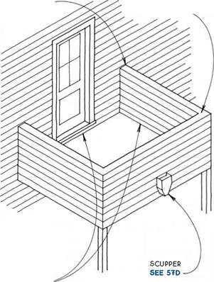
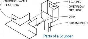
Waterproof deck with solid railing—Waterproof decks surrounded by a solid railing must be sloped to an opening in the railing. This opening can be a flashed hole in the wall, or scupper, as shown here, or it can be a gap in the wall that accommodates a stairway or walk. (Avoid directing water to walkways in climates with freezing temperatures.) The opening should be located away from the main structure of the building, and the floor should pitch toward the opening from all directions. In some cases, a second opening or overflow should be provided to guarantee that water won’t build up if the primary drain clogs.

wall/deck

connection

IS SAME AS

railing/deck connection see

DRAWINGS AT LEFT

Open deck with solid railing—Open decks sur­rounded by a solid railing are simple to drain since water will pass through the floor surface (see 55D). Care should be taken to provide adequate drainage from any surface below the deck.

COMPOSITE FLOOR TRUSSES

@ WOOD FLOOR TRUSSES

@ WOOD FLOOR TRUSSES@ WOOD FLOOR TRUSSES@ WOOD FLOOR TRUSSES

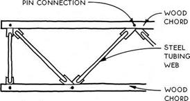
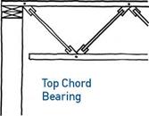
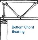
Wood top and bottom chords are linked with steel tubing webs in the composite truss. The tubing is pressed flat at the ends and connected to the wood chords with a metal pin. Unlike wood trusses with metal plates (see 45A above), the webs of the com­posite truss are entirely free to rotate (on the pins) and therefore allow the truss to return to its original shape when the load is removed.
Composite trusses are generally more heavy duty than their all-wood cousins illustrated in 45A above. The largest composite trusses are capable of spanning
over 100 ft. They are made with double 2x chords, which sandwich the webs. The lightest-duty composite trusses are made with single 2×4 chords oriented flat and dadoed to receive the webs.

Like wood floor trusses, composite trusses easily accommodate ducts and other utilities, which can be run through the open webs without altering the truss. Like all trusses, composite trusses are most practical for simple plans with long spans. Once engineered and installed, they are difficult to alter.