Category Construction

WOOD I-JOISTS FOR LOADS

Squash Blocks & Blocking Panels

WOOD I-JOIST CONNECTIONS

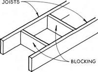
Blocking & Backer Blocks

WOOD I-JOISTS FOR LOADSWOOD I-JOISTS FOR LOADSWOOD I-JOISTS FOR LOADS

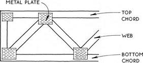
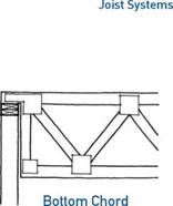
Four-by-two wood floor trusses are made up of small members (usually 2x4s) that are connected so that they act like a single large member. The parallel top and bottom chords and the webs are made of lumber held together at the intersections with toothed metal plates.

The open web allows for utilities to run through the floor without altering the truss. Round ducts from 5 in. to 16 in. in diameter can be accommodated, depending

on the depth of the truss. Truss depths vaiy from 10 in. to 24 in., with spans up to about 30 ft. Like I-joists, floor trusses are practical for long spans and simple plans, but difficult for complicated buildings.

Floor trusses are custom manufactured for each job, and cannot be altered at the site. Bearing walls, floor openings, and other departures from the simple span should always be engineered by the manufacturer.

Floor

Подпись: I-Joist

T

he floor is the part of the building with which we have most contact. We walk on the floor and, on occasion, dance, wrestle, or lie on it. We can easily tell if the floor is not level, if it is bouncy or squeaky, and this tells us something about the overall quality of the building. The floor carries the loads of our weight, all our furniture, and most of our other possessions. It also acts as a diaphragm to transfer lateral loads (e. g., wind, earthquake, and soil) to the walls, which resist these loads. Floors insulate us from beneath and often hold ductwork, plumbing, and other utilities. So a floor must be carefully designed as a system that integrates with the other systems of a wood-frame building—the foundation, walls, stairs, insulation, and utilities. Once designed, the floor must be carefully built because so many subsequent parts of the construction process depend on a level and solid floor construction.

Floor

elements of a floor system

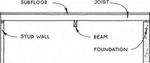
There are several floor-construction systems, and all of them are composed of variations of the same basic ele­ments: support, joists, and a subfloor.

Support—Wood floor systems usually span between parallel supports. These supports may be a foundation wall, a stud-bearing wall, or a beam. The first two are covered in Chapters 1 and 3, and beams are a subject of this chapter (see 29-31).

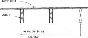
Joists—The primary structural members of a floor system are the joists, which span between the supports. The most common materials for joists are solid-sawn lumber (see 35-42) and engineered wood I-joists (see 43-44). Joists are usually placed on 12-in., 16-in., or 24-in. centers, depending on the required span and the sizes of the joists (see 32).

Solid-Sawn Joist

Subfloor—The planar structural surface attached to the top of the joists is called the subfloor (see 48-51). The subfloor provides the level surface to which the finish floor is applied, and it also acts as a diaphragm to transfer lateral loads to the walls. Subfloors are usually made of plywood or oriented strand board (OSB) but may also be made of other materials. Some subfloors also provide mass for passive-solar heating.

floors and walls

It is essential to coordinate the details of a floor-framing system with those of the wall framing. There are two wall-framing systems from which to choose:

FLOORS

Balloon framing—Balloon framing is a construction system in which the studs are continuous through the floor levels. It is a mostly archaic system, but there are some situations where balloon framing is appropriate. These situations are discussed in the introduction to Chapter 3 (see 65-66). Balloon-framing details that per­tain to floors are included in this chapter.

Platform framing—Platform framing is the domi­nant wood-floor construction system in this country. The platform frame floor is so named because the stud-wall structure stops at each level, where the floor structure provides a platform for the construction of the walls of the next level. This chapter concentrates on platform framing, which has two basic variations: joists with structural panels (OSB or plywood), and girders with decking.

types of floor framing

Throughout the history of the balloon frame and the more recent platform frame, floors have typically been made with joists (2×6, 2×8, 2×10, and 2×12) that are spaced closely (usually 16 or 24 inches on center) to support a subfloor that spans between them.

Floor

For 125 years, the joists were all solid-sawn lumber, and the subfloor started as boards, laid diagonally and later became plywood. In the past 35 years or so, solid – sawn lumber has been slowly replaced with engineered wood products—wood I-joists and other structural composite lumber (SCL). Engineered wood products are straighter, more dimensionally stable, and generally stronger than their solid-sawn counterparts. In addi­tion, they can be made larger and longer than sawn lumber, so they can span farther.

Currently, engineered wood products have over­taken solid-sawn lumber in terms of market share for floor construction, but both materials are still widely used. Subfloors are now typically made with Oriented Strand Board (OSB) instead of the more expensive plywood.

Most of the details in this chapter are illustrated with examples showing solid-sawn lumber—primarily because the drawings are more clear using these simple forms. However, the solid-sawn details may be inter­preted to be built of engineered products because the basic principles apply to all types of framing mate­rial whether solid-sawn, I-joist, or other composite materials. Because I-joists require special treatment in certain conditions, there is a section of the chapter devoted entirely to I-joists (see 43-44).

In areas where timber is plentiful, 4x girders with 2-in. tongue-and-groove subfloor decking that spans 4 ft. are often used as a floor system (see 46-47).

Lower grades of decking on girders make a very eco­nomical floor over crawl spaces, and appearance grades of decking are often used for exposed ceilings. The decking itself does not technically act as a diaphragm to resist lateral loads, so it may require additional diagonal structure, especially at upper levels.

Also included in this chapter are porch and deck floors, floor insulation, and vapor barriers.
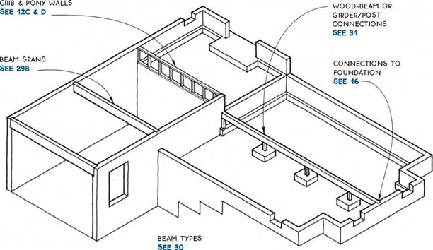
Floor

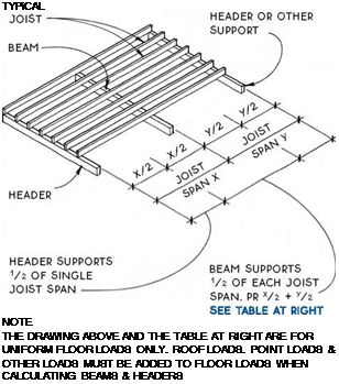
@ FLOOR BEAMS

Подпись: TYPiCAL NOTE THE DRAWING ABOVE AND THE TABLE AT RIGHT ARE FOR UNIFORM FLOOR LOADS ONLY. ROOF LOADS. POINT LOADS & OTHER LOADS MUST BE ADDED TO FLOOR LOADS WHEN CALCULATING BEAMS & HEADERS

BEAM SPAN COMPARISON

Joist span (У2 + У2)

Beam type

8ft.

10ft.

12ft.

14ft.

Beam span (ft.)

(2) 2×8 built-up beam

6.8

6.1

5.3

4.7

4×8 timber

7.7

6.9

6.0

5.3

31/8 in. x 7У2 in. glue-laminated beam

9.7

9.0

8.3

7.7

3V2 in. x 7У2 in. PSL beam

9.7

9.0

8.5

8.0

(2) 13/4 in. x 71/2 in. LVL (unusual depth)

10.0

9.3

8.8

8.3

4×8 steel beam

17.4

16.2

15.2

14.1

(W8 x 13 A36)

This table assumes a 40-psf live load and a 15-psf dead load. The table is intended only for estimating beam sizes and comparing beam types. For calculation tables, consult the national or regional organizations listed on pp. 228-229.

A) FLOOR beams
FloorFloor

Cut Timber

TIMBER BEAMS ARE AVAiLABLE IN A VARIETY OF SPECIES & GRADES; DOUGLAS-FIR IS THE STRONGEST. ACTUAL WIDTHS ARE 31/2 IN. AND 51/2 IN.; ACTUAL HEIGHTS ARE 51/2 IN., 71/2 IN., ETC., TO 131/2 IN.

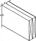
Built-Up Beam

SOLID SAWN LUMBER IS NAILED OR SCREWED TOGETHER TO FORM A SINGLE BEAM. WIDTHS ARE MULTIPLES OF 11/2 IN. HEIGHT FOLLOWS DIMENSION LUMBER.
FloorFloorFloorFloor

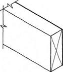
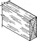
Laminated-Strand Lumber (LSL) Beam

FACTORY-MADE COMPOSITE BEAM USED FOR HEADERS, RIM JOIST, AND LIGHT-DUTY BEAMS. ACTUAL WIDTHS ARE 13/4 IN. AND 31/2 IN; ACTUAL HEIGHTS RANGE FROM 91/4 IN. TO 16 IN.

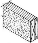
Parallel-Strand Lumber (PSL) Beam

FACTORY-GLUED LONG STRANDS OF VENEER MAKE VERY STRONG BEAMS. ACTUAL WIDTHS RANGE FROM 23/4 IN.

TO 7 IN; HEIGHTS RANGE FROM 91/4 IN. TO 18 IN. 51/2 IN., 71/2 IN., ETC., TO 131/2 IN.

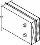
Flitch Beam

A STEEL PLATE SANDWICHED BETWEEN TWO PIECES OF LUMBER ADDS STRENGTH WITHOUT SUBSTANTIALLY INCREASING THE BEAM SIZE. THE LUMBER PREVENTS BUCKLING OF THE STEEL & PROVIDES A NAILING SURFACE. WIDTHS ARE 3 IN. TO 31/2 IN. HEIGHTS FOLLOW DIMENSION LUMBER.

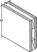
Box Beam

2X4 LUMBER IS SANDWICHED BETWEEN TWO PLYWOOD SKINS. PLYWOOD IS BOTH NAILED & GLUED TO 2X4S & AT ALL EDGES. PLYWOOD AND LUMBER JOINTS MUST BE OFFSET.
FloorFloor

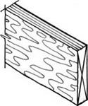
Laminated-Veneer Lumber (LVL) Beam

FACTORY-LAMINATED VENEERS MAKE STRONG BEAMS. USED INDIVIDUALLY OR GANGED TOGETHER. ACTUAL WIDTH IS – Із/* IN. (TWO PIECES MATCH THICKNESS OF 2X4 WALL) HEIGHTS RANGE FROM 51/2 IN. TO 24 IN.

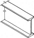
Steel Beam

THE STRONGEST OF THE BEAMS FOR A GIVEN SIZE, STEEL BEAMS ARE COMMONLY AVAILABLE IN VARIOUS SIZES FROM 4 IN. WIDE & 4 IN. HIGH TO 12 IN. WIDE &

36 IN. HIGH. THEY MAY BE PREDRILLED FOR BOLTING WOOD PLATE TO TOP FLANGE OR TO WEB.
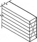
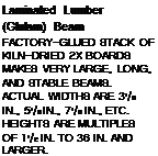
FloorПодпись: Laminated Lumber (Glulam) Beam FACTORY-GLUED STACK OF KILN-DRIED 2X BOARDS MAKES VERY LARGE, LONG, AND STABLE BEAMS. ACTUAL WIDTHS ARE 31/8 IN., 51/8 IN., 71/8 IN., ETC. HEIGHTS ARE MULTIPLES OF 11/2 IN. TO 36 IN. AND LARGER. FOR CONNECTIONS TO STEEL BEAMS SEE 37.

NOTE

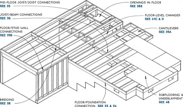
BEAMS & JOISTS MUST BE DESIGNED AS A SYSTEM. CONNECTIONS BETWEEN JOISTS & BEAMS ARE SIMILAR FOR ALL WOOD-BEAM TYPES.

SEE 36

@ BEAM TYPES


NOTE

Floor Floor Floor Floor

Подпись: Built-Up Beam KEEP ONE MEMBER CONTINUOUS OVER POSTS. Подпись: Metal Column METAL LALLY COLUMN HAS INTEGRAL METAL CONNECTOR.

Подпись: Plywood Gusset PLYWOOD GUSSETS ARE APPLIED TO BOTH SIDES OF SPLICED BEAMS. USE 5-PLY PLYWOOD. Подпись: Metal Connector METAL CONNECTORS ARE MANUFACTURED IN MANY CONFIGURATIONS FOR MOST TYPES OF WOOD BEAM & POST JOINTS.

WOOD BEAMS MAY BE SPLICED OVER VERTICAL SUPPORTS & OFTEN MAY BE ATTACHED TO THE SUPPORT BY MEANS OF TOENAILING. SOME SITUATIONS & CODES. HOWEVER. REQUIRE A POSITIVE CONNECTION OF BEAM TO POST SUCH AS A PLYWOOD GUSSET OR METAL CONNECTOR. SPLICE BEAMS ONLY OVER VERTICAL SUPPORTS UNLESS ENGINEERED. SPLICE WILL DEPEND ON ТУРЕ OF BEAM & ТУРЕ OF SUPPORT.

) WOOD BEAM OR GIRDER/POST CONNECTIONS
Floor

Floor

Both dimension-lumber and wood I-joists are common materials for floor structure. Both systems are flexible, and the materials are universally available. Species of lumber vary considerably from region to region, but sizes are uniform. The most common sizes for floors are 2×8, 2×10, and 2×12. Selection of floor – joist size depends on span; on spacing required for sub­flooring and ceiling finishes (usually 12 in., 16 in., or 24 in.); and on depth required for insulation (usually over a crawl space) and/or utilities (over basements and in upper floors).

The table at right compares spans at common on – center spacings for three typical species and grades of framing lumber at four different sizes of joist (2×6, 2×8, 2×10, and 2×12) and an I-joist at the two largest sizes. For information on wood I-joists, see 43 and 44; for information on wood trusses, see 45A.

This table assumes a 40-psf live load, a 10-psf dead load and a deflection of L/360. The table is for compar­ison and estimating purposes only.

ALLOWABLE FLOOR JOiST SPANS iN FEET

Joist size, species, and grade

Joist spacing (ft.)

12 in. o. c

16 in. o. c.

24 in. o. c.

2×6 hem-fir #2

10.0

9.0

7.9

2×6 spruce-pine-fir #2

10.2

9.3

8.1

2×6 Douglas fir #2

10.7

9.7

8.2

2×8 hem-fir #2

13.1

11.9

10.1

2×8 spruce-pine-fir #2

13.5

12.2

10.2

2×8 Douglas fir #2

14.1

12.7

10.4

2×10 hem-fir #2

16.8

15.1

12.3

2×10 spruce-pine-fir #2

17.2

15.3

12.5

2×10 Douglas fir #2

18.0

15.6

12.7

9.5 x 2.06-inch I-Joist

17.9

16.2

14.0

2×12 hem-fir #2

20.3

17.5

14.3

2×12 spruce-pine-fir #2

20.6

17.8

14.5

2×12 Douglas fir #2

20.8

18.0

14.7

11.9 x 2.06-inch I-joist

21.4

19.4

16.8

@ JOIST-FLOOR SYSTEMS

NOTE

iN EARTHQUAKE OR HURRiCANE zONES, SEcuRE Floor JOiSTS TO MuDSiLL with framing anchors. FOR JOiST span table SEE 32.

FRAMED WALL

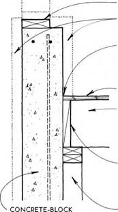
Подпись: CONCRETE-BLOCK OR CONCRETE FOUNDATiON WALLПодпись: FRAMED WALLПодпись:Подпись:Подпись:Подпись: BLOCKING BETWEEN JOiSTS HELPS TO RESIST LATERAL LOADS.Подпись: JOIST BOLTED OR NAILED TO WALLFloorПодпись: 30-LB. FELT MOiSTURE BARRiER BETWEEN FOUNDATiON WALL & UNTREATED WOODПодпись: CONCRETE-BLOCK OR CONCRETE FOUNDATiON WALLFloor

Floor
Floor

Подпись: FOUNDATiON WALLПодпись:Подпись:FloorПодпись:Подпись: BLOCKING BETWEEN JOiSTSFloorПодпись: SUBFLOORING

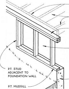
Подпись: FRAMED WALL p.T. MUDSiLL SEE 12A EXTERiOR OR iNTERiOR iNSULATiON SEE 15C 30-LB. FELT MOiSTURE BARRiER BETWEEN FOUNDATiON WALL & UNTREATED WOOD SUBFLOORING Подпись: FRAMED WALL p.T. MUDSiLL SEE 12A EXTERiOR OR INTERIOR INSULATION SEE 15c 30-LB. FELT MOiSTURE BARRiER BETWEEN FOUNDATiON WALL & UNTREATED WOOD
Подпись: FRAMED WALL SEE 15D
Подпись: OR cONcRETE FOUNDATiON WALL

p. T. MUDSiLL SEE 12A

EXTERiOR OR INTERIOR INSULATION SEE 150

30-LB. FELT MOiSTURE BARRiER BETWEEN FOUNDATiON WALL & UNTREATED WOOD

SUBFLOORING

JOIST W/ FULL BEARING ON 2X4 SILL

blocking BETWEEN JOiSTS

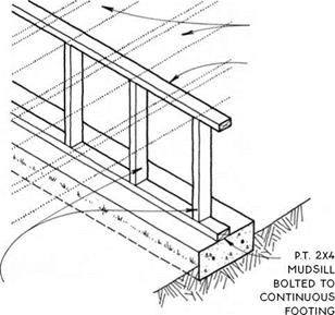
p. T. 2X4 SILL W/ 1/2-IN. anchor BOLTS AT 6 FT O. c.

NOTE

Подпись: JOISTS BELOW MUDSILL Подпись: JOISTS BELOW MUDSILL

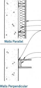
FOR DETAIL W/ JOiSTS pARALLEL TO WALL SEE 33B.

Подпись: Parallel to Wall/All Support SystemsPerpendicular to Wall/Stepped Wall Support

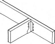
Metal Joist Hanger

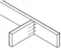
Подпись: Nailed through Joist THE SIMPLEST BUT THE WEAKEST METHOD IS RECOMMENDED ONLY FOR BLOCKING.

Floor Floor
Floor

Floor

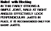
Подпись: Nailed with Blocking iN THiS FAiRLY STRONG & SiMPLE JOiNT, NAiLS AT RiGHT ANGLES EFFECTiVELY LOCK PERPENDiCULAR JoiSTS iN PLACE. ІТ iS RECOMMENDED ONLY FOR SHORT JoiSTS.
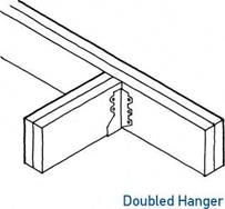
Подпись: DOUBLED HANGERS ARE SizED TO HOLD Two piEcES oF DiMENSioN LuMBER.

THiS iS the strongest of the standard methods. each approved HANGER iS RATED iN pounds.

notes
Floorfor metal hangers, use common (not box)

NAiLS. HANGER MANuFACTuRERS SpEciFY NAiL

SizE for each hanger type.

use coNSTRucTioN ADHESivE AT METAL JoiST HANGERS To REDucE FLooR SQuEAKING.

for floor openings SEE 38B.

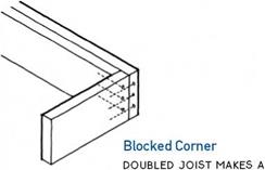
STRONG OUTSIDE CORNER FOR CANTILEVERS SEE 39A AND DECKS SEE 52

/дЛ JOIST/JOIST CONNECTIONS

‘—J Nailed through Joist

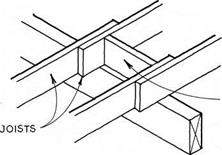
BuTT JOiSTS TO MAINTAIN SAME SpAciNG FOR NAILING THE SuBFLOOR ON EAcH SIDE OF THE BEAM.

NOTE

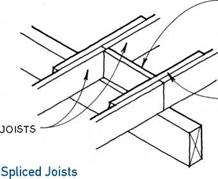
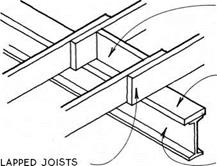
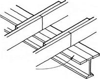
LAppED JOiSTS & SpLicED JOiSTS ARE cOMMONLY uSED OvER A cRAwL Space OR OTHER LOcATION

where head clearance below the beam is NOT required.

FloorПодпись:FloorПодпись:Подпись: SCAB NAILED TO SIDE OF JOiSTS Floor

Подпись: NOTE SCAB MUST BE LONG ENOUGH TO QUALIFY SpLicE AS A SINGLE JOIST SO THAT ADEQUATE BEARING ON BEAM IS ACHIEVED. vERiFY wiTH LOCAL CODES.
Подпись: Lapped Joists THiS COMMON JOiNT REQUiRES SHiFTiNG THE SUBFLOOR LAYOUT 11/2 iN. ON OppOSiTE SIDES OF THE BEAM TO ALLOw THE SUBFLOOR TO BEAR ON THE JOiSTS.

JOIST/WOOD BEAM CONNECTIONS

Floor

Beam below Joists

Подпись: Joist HangersПодпись: ALIGN JOiSTS ON EAcH SIDE OF BEAM TO MAINTAIN SAME SpAciNG FOR SuBFLOOR NAILING.Joists on Ledger

A 2X2 OR 2X4 LEDGER NAILED TO THE BEAM SuppORTS THE JOiSTS. TOENAIL THE JOiSTS TO THE BEAM OR BLOcK BETwEEN JOiSTS. NOTcH JOiSTS TO 1/4 OF depth IF required TO FIT OVER THE LEDGER.

NOTE

JOIST HANGERS & JOiSTS ON LEDGER ARE uSED wHERE MAXIMuM HEAD cLEARANcE IS REQuiRED BELOw THE FLOOR. THEY wORK BEST IF THE JOiSTS & BEAM ARE OF SIMILAR SpEciES & MOISTuRE cONTENT SO THAT ONE DOES NOT SHRINK MORE THAN THE OTHER.

JOIST/WOOD BEAM CONNECTIONS

Beam Flush with Joists

Floor

BLOCKING BETWEEN JOISTS AS REQUIRED

2X NAILING PLATE BOLTED TO UPPER BEAM FLANGE


2X2 WOOD STRAPS NAILED TO JOiSTS OVER STEEL BEAM MAINTAIN JOIST ALIGNMENT.


JOIST


Floor

STEEL BEAM


SEE 36A


blocking

BETWEEN JOISTS AS

required

2X NAILING pLATE BOLTED to upper BEAM FLANGE


2X NAILING PLATE BOLTED TO UPPER BEAM FLANGE „


JOISTS


STEEL BEAM


SEE 36A


Joists on Nailing Plate


Floor

NOTE

USE ONLY IN CONDITIONS WITHOUT UPLIFT FORCES AND WHERE SCABS WILL NOT INTERFERE WITH CEILING.


Floor

-IX BOARDS SCABBED TO UNDERSIDE OF JOISTS KEEP JOISTS ALIGNED & PREVENT LATERAL MOVEMENT OF STEEL BEAM.


Joists on Steel Beam


NOTE

THE DETAILS SHOWN IN 37A & В MAY BE ADJUSTED FOR USE WITH OTHER TYPES OF JOISTS & GIRDERS DISCUSSED IN THE FOLLOWING SECTIONS.


Joists Hung from Double Nailer


JOIST/STEEL BEAM CONNECTIONS

Beam Flush with Joists


JOIST/STEEL BEAM CONNECTIONS

Beam below Joists


FloorFloorFloorFloorFloor

Подпись: Block Bridging SOLiD BLOCKiNG FROM SAME MATERiAL AS JOiSTS iS STAGGERED FOR EASE OF NAiLiNG. Floor

Floor

Floor

note

for deep JOiSTS wiTH long spans (Over 10 ft.), local codes may REQuiRE Bridging TO pREvENT ROTATiON & TO Distribute THE LOADING.

Metal Bridging

METAL PiECES SHOULD

not touch each other.

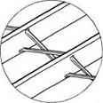
Cross Bridging

5AX3 OR 5AX4 OR 2X2 OR 1X4 BOARDS ARE NAILED IN A cROSS PATTERN BETWEEN JOiSTS. PiEcES SHOULD NOT TOUcH EAcH OTHER.

A BRIDGING

Floor

Подпись: DOUBLE HEADER JOiSTS AT ENDS OF OPENINGSПодпись: PERPENDICULAR JOIST CONNECTIONS SEE 35Подпись: DOUBLE TRIMMER JOiSTS AT SIDES OF OPENINGFloorSmall Openings

OPENINGS THAT FIT BETWEEN TWO JOiSTS FOR LAUNDRY cHUTES OR HEATING DUcTS ARE SIMPLY MADE BY NAILING BLOcKiNG BETWEEN THE JOiSTS.

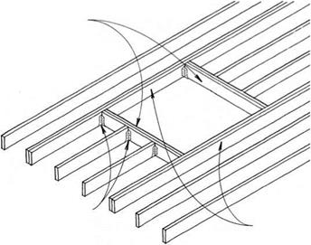
Large Openings

IN OPENINGS THAT ARE WIDER THAN THE JOIST SPAciNG, SUcH AS FOR THE STAIRWAYS & cHIMNEYS, THE FLOOR STRUCTURE AROUND THE OPENING MUST BE STRENGTHENED. FOR OPENINGS UP TO THREE JOIST SPAcES WIDE, DOUBLE THE JOiSTS AT THE SIDES & ENDS OF THE OPENING MAY SUFFicE. WIDER OPENINGS SHOULD BE ENGINEERED.

OPENINGS IN JOIST-FLOOR SYSTEM

DOUBLE SiDE JOiSTS FOR TWiCE THE DiSTANCE OF THE CANTiLEVER


EXTEND CANTiLEVERED JOiSTS TWiCE AS FAR iNTO THE BUiLDiNG AS THE LENGTH OF THE CANTiLEVER.


CANTiLEVERED wALLS SEE 73C


double JOiSTS AT SIDES OF

cantilever.

CORNER JOINT SEE 35

JOIST/JOIST CONNECTIONS SEE 35


RiM Blocking MAY Be SET 1-IN. OuT

from mudsill to provide soffit nailing.


mudsill (FIRST-FLOOR FRAMING) OR DOuBLE TOp pLATE (uppER-FLOOR FRAMING) SuppORTS CANTiLEvERED JOiSTS.


FLOOR CANTILEVERS______

Parallel & Perpendicular to Joist System


FloorFloor

Floor

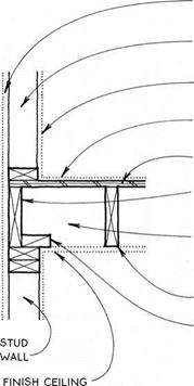
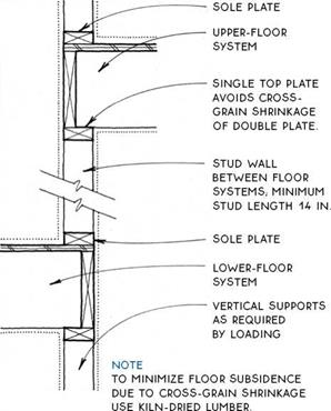
FloorJoist floor-system connections to exterior walls are straightforward. The wall framing may be one of two types.

Platform framing – Platform framing, the most common system in use today, takes advantage of stan­dard materials and framing methods. The ground floor and all upper floors can be constructed using the same system.

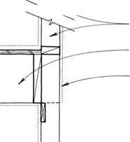
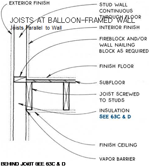
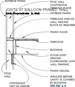
Balloon framing – Balloon framing is rarely used because it is harder to erect and requires veiy long studs. It may be the system of choice, however, if the floor structure must work with the walls to resist lateral roof loads or if extra care is required to make the insu­lation and vapor barrier continuous from floor to floor, (see 41A, B)

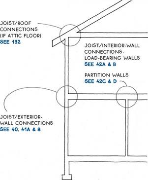
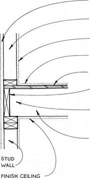
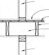
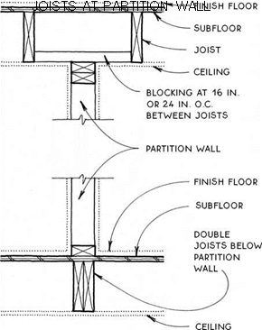
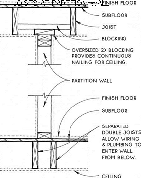
Joist floor-system connections to interior walls depend on whether the walls are load-bearing walls or partition walls. The other factor to consider is whether edge nailing is required for the ceiling.

FloorJOIST/STUD-WALL CONNECTIONS

EXTERiOR Finish

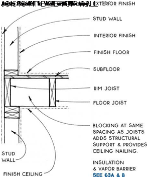
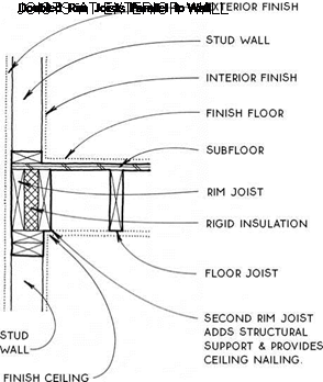
Подпись: EXTERiOR FiNiSH STUD WALL iNTERiOR FiNiSH FiNiSH FLOOR SUBFLOOR RiM JOiST (OR RiM BLOCKiNG) iNSULATiON & VAPOR BARRIER SEE 63A & B FLOOR JOiST FloorFloorstud wall

INTERIOR FiNiSH FiNiSH FLOOR SuBFLOOR Rim JOiST

insulation & vapor barrier SEE 63A & B

FLOOR JOiST

2X4 Blocking FOR NAILING

Floor

Floor Floor

ceiling

FloorПодпись: LEVEL CHANGE

Подпись: ;^i і Floor

Подпись: CONTINUOUS STUDSПодпись: LOWER-FLOOR SYSTEM INTERIOR FINISH FloorFloor

Floor
Floor

NOTE

STuD LAYOuT MuST BE OFFSET 11/2 IN. FROM JOIST LAYOuT.

continuous studs avoid the cross-grain shrinking OF

PLATES IN DETAIL SEE 41C.

LEVEL CHANGE

BEARING STuD WALL; STuDS ALIGNED WITH joiSTS &

Подпись: BEARING STUD WALLПодпись: NOTE BLOCKING CAN BE ELIMINATED IF BEARING WALL ALIGNS WITH JOIST.Подпись: FINISH FLOOR SUBFLOOR JOIST BLOCKING AT 16 IN. OR 24 IN. o.c. ALIGNED WITH STUDS ABOVE & BELOW. FloorПодпись: BEARING STuD WALL (OR BEAM) BELOW; STUDS ALIGNED WITH BLocKING & STUDS ABOVE. Floor
studs below

FINISH FLooR

subfloor

joist

block if joist is spliced over

BEARING WALL SEE 36A

BEARING STuD WALL (oR BEAM) below; studs ALIGNED WITH JoiSTS (BEARING WALL IS

not required if joists ARE

Floor Floor

ENGINEERED To Support Top BEARING WALL).

Подпись: Alternative DetailsJoists Parallel to Wall

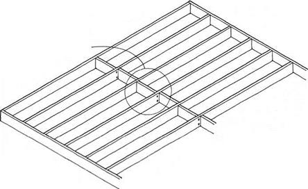
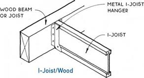
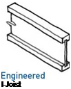
Wood I-joists are designed to work efficiently, with most of the wood located at the top and bottom of the joist where the bending stresses are greatest. Called flanges, the top and bottom are generally made of lami­nated or solid wood; the slender central part of the joist, the web, is made of plywood or OSB. I-joists are straighter and more precise than dimension lumber and therefore make a flatter, quieter floor. Their spanning capacity is only slightly greater than that of dimension lumber, but because they can be manufactured much deeper and longer than lumber joists (up to 30 in. deep and 60 ft. long), they are the floor-framing system of choice when long spans are required.

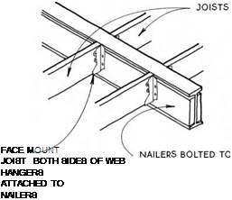
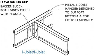
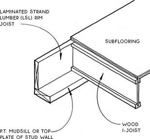
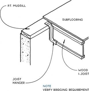
Подпись: NOTE ROUND OR RECTANGULAR HOLES FOR UTiLITIES MAY BE CUT IN WEB. THE FARTHER FROM THE SUPPORT, THE LARGER THE HOLE CAN BE. 1V2-IN.-DIAMETER ROUND HOLES MAY BE CUT ALMOST ANYWHERE IN THE WEB. VERIFY HOLE SIZE AND LOCATION WITH MANUFACTURER. Подпись: THICKNESS OF BACKER BLOCKS & WEB STIFFENERS SEE 43BПодпись: WIDTHS: 1V2 IN., 2 IN., 31/2 IN. FloorПодпись: A WOOD I-JOISTSFloorПодпись: PLYWOOD OR OSB Подпись:FloorWood I-joists are designed to be part of a system composed of engineered beams, joists, and sheathing. Laminated strand lumber (LSL) rim joists and laminated veneer lumber (LVL) beams are sized to integrate with the joists. In cases of extreme loading, composite beams may be substituted for I-joists. The system is completed with span-rated tongue-and-groove sheathing nailed to the joists and reinforced with construction adhesive.

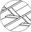
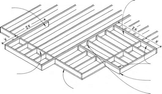
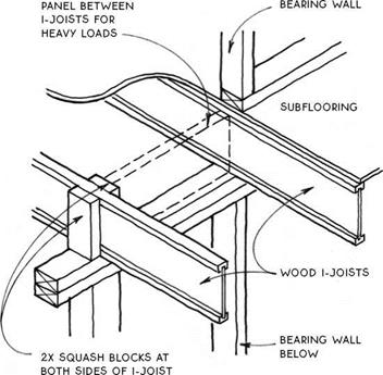
Because the web is thin, I-joists are about 50% lighter than lumber joists. But the thin web also means I-joists do not have as much strength to resist vertical crushing forces. For this reason, the web often must be reinforced with plywood or OSB web stiffeners. Nailed to the web, these stiffeners occur at connectors for deep joists, and in other conditions as required by manufacturers’ specifica­tions and local codes. When vertical loads are extreme, I-joists can be reinforced by attaching sections of 2x fram­ing lumber called squash blocks to their sides or by fas­tening LSL blocking panels between them (see 44C).

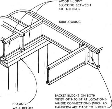
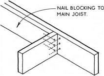
When other framing members need to be attached to the side of an I-joist, backer blocks are added to the webs of the I-joists. Like web stiffeners, backer blocks are made of plywood or OSB, but their primary purpose is to provide a planar, thick nailing surface rather than to resist vertical loads (see 44D).

Like dimension lumber, wood I-joists are easily cut and joined on site. The production and fastening of backer blocks, web stiffeners, and so forth for I-joist systems can offset the construction time gained by not having to sort for defects.

Floor

Floor

NOTE

LSL RiM JOiSTS ARE SiZED TO CORRESPOND WiTH THE DEPTH OF WOOD i-JOiSTS.

DO NOT USE SAWN-LUMBER RiM.


Floor

FOR Tall JOiSTS.


Подпись: WOOD I-JOISTS AT RIM JOIST Joists on Mudsill or Top Plate FloorWOOD I-JOISTS AT RIM JOIST

Joists Flush with Mudsill

LSL BLOc^NG

Floor

For Heavy LOADS


Floor

FOUNDATION & STORM DRAINAGE

FOUNDATION & STORM DRAINAGE

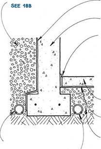
Drainage is essential in protecting a basement from groundwater, but waterproofing the basement wall from the outside is also vital. In selecting a water­proofing material, consider the method of application, the elasticity, and the cost. Below are common water­proofing and drainage materials.

Bituminous coatings—Tar or asphalt can be rolled, sprayed, troweled, or brushed on a dry surface. Often applied over a troweled-on coating of cement plaster that is called parging, some bituminous coatings may be fiberglass reinforced. They have minimal elasticity, and thin coats may not be impervious to standing water.

Modified portland-cement plaster—Plaster with water-repellent admixtures can look exactly like stucco. It is usually applied with a brush or a trowel to a moist­ened surface. It is inelastic, and unlike parging, it is waterproof.

Bentonite—A natural clay that swells when moistened to become impervious to water, bentonite is available as panels, in rolls, or in spray-on form. It is applied to a dry surface, and is extremely elastic.

Membranes—Rubberized or plastic membranes that are mechanically applied or bonded to a moist or dry surface are moderately elastic.

Bitumen-modified urethane—The most recent development in waterproof coatings, bitumen-modified urethane is applied with a brush to a dry surface. It is elastic, protecting cracks up to Vs in.

Plastic air-gap materials—These drainage mate­rials create a physical gap between the basement wall and the soil. A filter fabric incorporated in the material allows water to enter the gap and drop to the bottom of the wall. These systems are expensive, but they elimi­nate the need for gravel backfill.

Although waterproofing and drainage will prevent water from entering the basement, water vapor may migrate into the basement through the footing and basement wall. It’s important not to trap this vapor in an insulated wall, so a vapor barrier on the warm side of a basement wall is not recommended. More common and more practical is to allow the vapor to enter the space, and to remove the vapor with ventilation or a dehumidifier.

WATERPROOFING

Principles & Materials

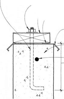
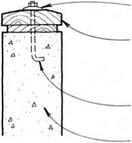
MALLEABLE OR OTHER LARGE WASHER

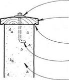
WEATHER-RESiSTANT WOOD CAP BEVELED ON TOP FOR DRAiNAGE

DRIP CUT iN UNDERSiDE OF cap

anchor bolts at 6 ft. o. c. minimum.

concrete-block OR concrete wall


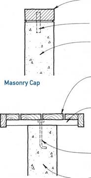
rowlock brick OR paver cap


MASONRY TIES AT 2 FT. O. c.

concrete-block OR concrete wall


WEATHER-RESiSTANT WOOD SEAT NAILED

or screwed TO supports

P. T. 2x OR 4X SuPPORTS BOLTED PERPENDicuLAR TO WALL AT 2 FT. Oc. OR PER capacity OF FINISH SEAT MATERIAL


One-Piece Wood Cap


MALLEABLE OR OTHER

large washer

WEATHER-RESiSTANT TWO-PiEcE WOOD cAP; TOP piece beveled & WITH DRIP

anchor BOLTS AT 6 ft. o. c. minimum.

concrete-block OR concrete wall


ANcHOR BOLTS AT 2 FT. O. c. & REcESSED flush into supports

concrete-block or concrete wall


Wood-Bench Cap


Two-Piece Wood Cap


FOUNDATION & STORM DRAINAGEFOUNDATION & STORM DRAINAGEFOUNDATION & STORM DRAINAGE

FOUNDATION & STORM DRAINAGE

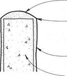
FOUNDATION & STORM DRAINAGEПодпись: Stucco Cap
Подпись: ROUNDED SHAPE PROMOTES DRAiNAGE. STuccO OR WALL CONTINUOUS OVER CAP. FOR STuccO DETAILS SEE 118-119 SILicONE cOATING FOR MOISTURE PROTECTION CONCRETE-BLOCK OR CONCRETE WALL NOTES

THESE DETAILS ARE FOR THE TOPS OF RETAINING WALLS, WHicH ARE uSuALLY ExPOSED TO THE WEATHER. WOOD caps WILL ultimately decay, SO THEY ARE DESIGNED FOR RELATivE EASE OF REPLAcEMENT. THERE IS NOT MucH POINT IN MOiSTuRE BARRIERS, SiNcE THEY WILL ONLY TRAP RAINWATER AGAINST THE WOOD. RETAINING – WALL SuRFAcES SHOuLD BE PROTECTED FROM MOiSTuRE PENETRATION TO PREvENT DAMAGE FROM THE FREEZE – THAW cYcLE. SEAL WITH cLEAR AcRYLic OR SILicONE, OR WATERPROOF WITH MODIFIED PORTLAND-cEMENT PLASTER

or bitumen-modified urethane.

SEE 180

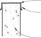
FOUNDATION & STORM DRAINAGEПодпись: Metal Capcontinuous metal cap with drip edge

FASTEN METAL cAP TO WALL AT SIDE TO

prevent moisture

PENETRATION OF TOP FLAT SuRFAcE.

concrete-block OR concrete wall

@ CONCRETE & CONCRETE-BLOCK WALL CAPS

FOUNDATION & STORM DRAINAGE

FOUNDATION & STORM DRAINAGE

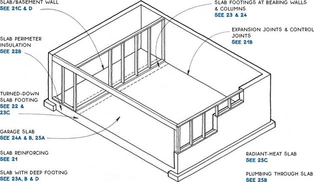
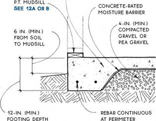
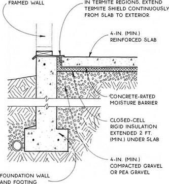
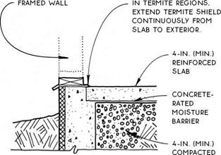
Preparation before pouring a slab is critical to the quality of the slab itself. The primary goals in preparing for a slab are to provide adequate and even support, and to control ground moisture.

Soil—Soil is the ultimate support of the slab. Soil must be solid and free of organic material. Some soils require compaction. In termite areas, the soil is often treated chemically. Verify compaction and soil treat­ment practices in your local area.

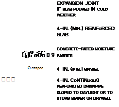
Gravel—Gravel is a leveling device that provides a porous layer for groundwater to drain away from the slab. A minimum of 4 in. of gravel is recommended. Gravel must be clean and free from organic matter. Crushed and ungraded gravels must be compacted. Graded gravels such as pea gravel composed entirely of similar-sized round particles cannot and need not be compacted.

Moisture barrier—Moisture barriers prevent mois­ture (and retard vapor) from moving upward into a slab. Six-mil polyethylene is common and works well in Detail A. Overlap joints 12 in. and tape the joints in

SLABS
areas of extreme moisture. A more substantial concrete-rated moisture barrier is necessary for Detail B because the moisture barrier is in direct contact with the concrete slab. Polyethylene may deteriorate within

CONCRETE

SLAB ‘ ~ …___ ^

A A. . ‘ 4 . • C.

FOUNDATION & STORM DRAINAGE

a very short period in this situation, and it is easily punctured during slab preparation and pouring. A more substantial concrete-rated barrier is a fiber – reinforced bituminous membrane, sandwiched between two layers of polyethylene.

Sand—Sand (shown only in Detail A), allows water to escape from concrete in a downward direction during curing. This produces a stronger slab. The American Concrete Institute recommends a 2-in. layer of sand below slabs.

Welded wire mesh—Welded wire mesh (WWM) is the most common reinforcement for light-duty slabs. The most common size is 6×6 (w1.4 x w1.4)—adequate for a residential garage, which requires a stronger slab than a house. One disadvantage to WWM is that the 6-in. grid is often stepped on and forced to the bottom of the slab as the concrete is poured.

Rebar—Rebar is stronger than welded wire mesh.

A grid of #3 rebar at 24 in. o. c is also adequate for a residential garage.

Fiber reinforcement—Fiber reinforcement is a re­cent development in slab reinforcement. Polypropylene fiber reinforcement is mixed with the concrete at the plant and poured integrally with the slab, thereby elim­inating difficulties with placement of the reinforcing material. The addition of 1.5 lb. of fiber per cubic yard of concrete produces flexural strength equal to WWM in a slab. The appearance of the slab is affected by the presence of fibers exposed at the surface.

Expansion joints—Expansion joints allow slabs to expand and contract slightly with temperature changes. They also allow slabs to act independently of building elements with which they interface. Expansion joints are appropriate at the edges of slabs that are not heated (not in the living space) or that, for some other reason, are expected to change temperature significantly over their lifetimes. Expansion joints are also used to isolate building elements that penetrate slabs such as struc­tural columns, walls, or plumbing (see 25B).

Control joints—Control joints induce cracking to occur at selected locations. They are troweled or cut into the surface of a slab to about one-quarter of the slab depth and at 20-ft. intervals. Cold joints, which automatically occur between sections of a slab poured separately, can act as control joints.

Подпись: CONCRETE-SLAB JOiNTSCONCRETE-SLAB REiNFOROiNG

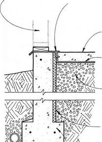
backfill & DRAiNAGE


waterproofing SEE 18C

BASEMENT WALL

bituminous expansion joint or leave 1-iN. space between SLAB & WALL To relieve excess hydrostatic pressure from below slab

4-IN. (Min.) reinforced slab

concrete-rated moisture barrier

6-IN. (Min.) gravel


WATERPROOFiNG SEE 18C

BASEMENT WALL


BACKFiLL & DRAiNAGE SEE 18B


FOUNDATION & STORM DRAINAGE

O*o X О rv о0


4o°§Oo

0O°oOn0° о о о 0 ° OoOoQO о °o ° о О °0 ООол<

О о о О, Уо і


00°С> а 0ОрО


4-IN. CoNTiNuouS

perforated drainpipe sloped to daylight or to storm sewer


FOUNDATION &amp;amp; STORM DRAINAGEFOUNDATION &amp;amp; STORM DRAINAGEFOUNDATION &amp;amp; STORM DRAINAGEFOUNDATION &amp;amp; STORM DRAINAGE

FOUNDATION &amp;amp; STORM DRAINAGE

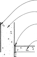
SLAB/BASEMENT WALL

SLAB/BASEMENT WALL

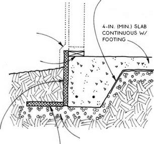
4-IN. (MiN.) REiNFORCED SLAB CONTiNUOUS WITH FOOTING

FOUNDATION &amp;amp; STORM DRAINAGE

NOTE

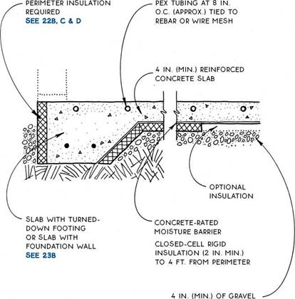
an uninsulated & exposed perimeter slab IS appropriate ONLY For uNHEATED spaces or in very warm climates.

NOTE

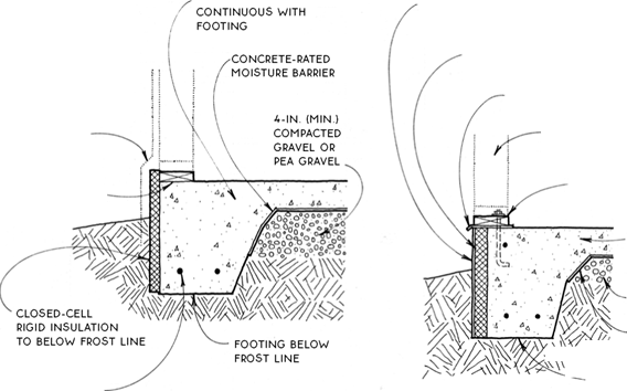
SLABS LOSE HEAT MOST READILY AT THEIR PERIMETERS. WHERE THEY ARE EXPOSED TO THE AIR. SO SLABS MUST BE PROTECTED FROM HEAT LOSS BY A CLOSED-CELL RIGID INSULATION PLACED AT THEIR EDGES. THE AMOUNT OF INSULATION REQUIRED WILL DEPEND ON THE CLIMATE AND ON WHETHER THE SLAB IS HEATED.

THE POSITION OF THE INSULATION WILL DEPEND PRIMARILY ON THE FOUNDATION ТУРЕ. SLABS INTEGRAL WITH TURNED-DOWN FOOTINGS ARE INSULATED AT THE OUTSIDE BUILDING EDGE. SLABS WITH DEEP FOOTINGS ARE OFTEN INSULATED AT THE INSIDE FACE OF THE FOUNDATION. ALTHOUGH THEY MAY ALSO BE INSULATED AT THE OUTSIDE BUILDING EDGE.

FOUNDATION &amp;amp; STORM DRAINAGE

turned-down deep footings

Footings SEE 23A, B & D

SEE 220 & D, 230

SLAB WITH TURNED-DOWN FOOTING

Warm Climate, Well-Drained Soil


SLAB PERIMETER INSULATION


4-IN. (MIN.) SLAB


FOUNDATION &amp;amp; STORM DRAINAGE

WALL FINISH:

STuCCO-WRAppED

insulation

OR SIDING

stopped at top of insulation

WITH FLASHING

& protective

COATING OVER

insulation


TERMITE SHIELD IF REQuiRED


FRAMED WALL pROJECTED OVER INSuLATION AND COATING


p. t. mudsill SEE 12A OR B


p. t. mudsill SEE 12A OR B


FOUNDATION &amp;amp; STORM DRAINAGE

REBAR CONTINuOuS

at perimeter


FOUNDATION &amp;amp; STORM DRAINAGEFOUNDATION &amp;amp; STORM DRAINAGE

FOUNDATION &amp;amp; STORM DRAINAGE

SLAB WITH TURNED-DOWN FOOTING

Insulation Outside Framing

SLAB WITH TURNED-DOWN FOOTING

Insulation Flush with Framing

Подпись:Подпись:Подпись: 4-IN. (MIN.) REINFORCED SLABПодпись:Подпись:FOUNDATION &amp;amp; STORM DRAINAGEFOUNDATION &amp;amp; STORM DRAINAGE

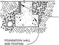
FOuNDATION wALL And FOOTING

closed-cell RiGiD iNSuLATiON TO BELOw Frost LiNE OR 2 Ft. (MiN.)

SEE 22B

A SLAB ON GRADE/DEEP FOOTING

Vertical Interior Insulation

SLAB ON GRADE/DEEP FOOTING

Horizontal Interior Insulation

concrete-rated

MOiSTuRE BARRiER


flashing & protective coating over insulation


p. t. mudsill SEE 12A OR B


gravel OR pea gravel


vertical closed-cell rigid insulation


4-in. (min.) compacted gravel or pea gravel


closed­cell rigid insulation TO below FROST LINE OR 2 ft. (MIN.) SEE 22B


NOTE

required dimensions & r-value of insulation vary w/ climatic zone.


horizontal closed­cell rigid insulation


FOUNDATION &amp;amp; STORM DRAINAGEFOUNDATION &amp;amp; STORM DRAINAGEFOUNDATION &amp;amp; STORM DRAINAGE

FOUNDATION &amp;amp; STORM DRAINAGE

SLAB WITH TURNED-DOWN FOOTING

Frost-Protected Shallow Footing

SLAB ON GRADE/DEEP FOOTING

Vertical Exterior Insulation

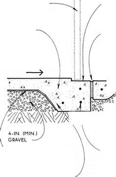
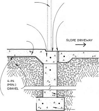
recessed threshold cast into slab TO control water

caulked expansion

JOINT


GARAGE DOOR


GARAGE DOOR


recessed threshold cast

INTO SLAB TO

control water caulked

expansion joint


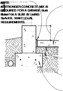
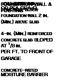
4-IN. (MiN.) REiNFORCED SLAB SEE 21A


thicken slab edge at foundation connection & TIE with rebar


SLOPE SLAB TOWARD DOOR AT 1/8 In. pER Ft.


4-IN. (MIN.)

reinforced slab SEE 21A


slope driveway AWAy from building

—>


FOUNDATION &amp;amp; STORM DRAINAGE

gravel


concrete-rated moisture barrier


REBAR

continuous at perimeter


FOUNDATION &amp;amp; STORM DRAINAGE

foundation

WALL


FOOTING

continuous with slab SEE 22c


FOOTING


TURNED-DOWN FOOTING

At Garage Door


FOUNDATION &amp;amp; STORM DRAINAGE

NOTE


WOOD pOST


REBAR


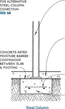
STEEL cOLuMN WITH STEEL BEARING pLATE AT BOTTOM BEARS ON FOOTING.


concrete

RATED

moisture

BARRIER


galvanized STEEL column base

SEE 6B


p. T. SILL plate NAILED TO SLAB WITH concrete NAILS

30-LB. FELT uNDER p. T. SILL


mmwmm

Wood Post


reinforced SLAB poured around column locks column in place.


REBAR

concr

RATED

moisture

BARRIER


NOTE

DEpTH & FLAT BEARING SuRFAcE OF FOOTING MuST BE

sized to support vertical LOADS.


REBAR


independent column FOOTING under slab


Bearing Wall


INTEGRAL SLAB FOOTING

Wood Post & Bearing Wall


FOUNDATION &amp;amp; STORM DRAINAGE

FOUNDATION &amp;amp; STORM DRAINAGEFOUNDATION &amp;amp; STORM DRAINAGEFOUNDATION &amp;amp; STORM DRAINAGEFOUNDATION &amp;amp; STORM DRAINAGEFOUNDATION &amp;amp; STORM DRAINAGE

FOUNDATIONS

FOUNDATION &amp;amp; STORM DRAINAGE FOUNDATION &amp;amp; STORM DRAINAGE FOUNDATION &amp;amp; STORM DRAINAGE

Utilities

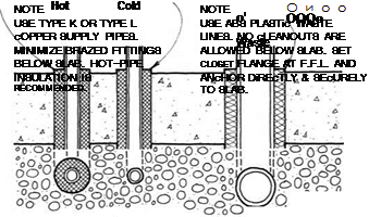
A GARAGE SLAB/FQUNDATIQN WALL ҐВ PLUMBING THROUGH SLAB

FOUNDATION &amp;amp; STORM DRAINAGENOTE

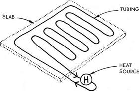
cROSS-LiNKED POLYETHYLENE TUBING (PEX) HAS REPLAcED cOPPER TUBING AS THE cONvEYOR OF HOT WATER FOR RADIANT SLABS. THIS ELASTic TUBING IS SUPPLIED IN LONG ROLLS & cAN cOvER ABOUT 200 SQ. FT. WITHOUT ANY JOINTS BELOW THE SURFAcE. THE ADDITION OF INSULATION BELOW THE SLAB WILL IMPROvE THE PERFORMANcE OF THE SYSTEM.

FOUNDATION &amp;amp; STORM DRAINAGE

Diagram of Radiant Heat Tubing

RADIANT-HEAT SLAB

chapter

About the drawings

The sizes of building elements indicated in the draw­ings in this section are for the purposes of illustrating principles and reminding the designer and the builder to consider their use carefully. These drawings should therefore be used only for reference.

Подпись: w

Подпись: ■ * t
About the drawings

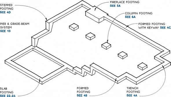
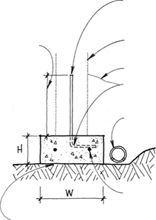
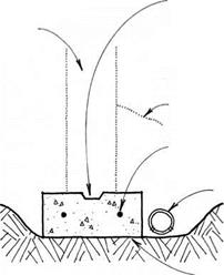
Footings are the part of a foundation that transfers the building’s loads—its weight in materials, contents, occupants, and snow, and possibly wind and earthquake loads—directly to the ground. Consequently, the size and type of footing should be matched carefully to the ground upon which it bears.

Soil type—Concrete footings should be placed on firm, undisturbed soil that is free from organic mate­rial. Soil types are tested and rated as to their ability to support loads (bearing capacity).

Compaction of soil may be required before footings are placed. Consult a soil engineer if the stability of the soil at a building site is unknown.

r SOIL TYPE

BEARING CAPACITY (PSF) 1

Soft clay or silt

do not build

Medium clay or silt

1,500-2,200

Stiff clay or silt

2,200-2,500

Loose sand

1,800-2,000

Dense sand

2,000-3,000

Gravel

2,500-3,000

Bedrock

4,000 and up

Reinforcing—Most codes require steel reinforcing rods (called rebar) in footings. Rebar is a sound invest­ment even if it is not required, because it gives tensile strength to the footing, thereby minimizing cracking and differential settling. Rebar is also the most common way to connect the footing to the foundation wall. For rebar rules of thumb, see 5B.

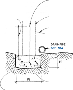
Size—Footing size depends mainly on soil type and the building’s weight. The chart below shows footing sizes for soils with bearing capacities of 2,000 pounds

per square foot

(psf).

Г NO. OF STORIES

H

W

1

6 in.

12 in.

2

7 in.

15 in.

3

8 in.

18 in.

A rule of thumb for estimating the size of standard footings is that a footing should be 8 in. wider than the foundation wall and twice as wide as high.

Frost line—The base of the footing must be below the frost line to prevent the building from heaving as the ground swells during freezing. Frost lines range from 0 ft. to 6 ft. in the continental United States. Check local building departments for frost-line requirements.

@ FOOTINGS

LENGTH OF
REBAR STUB
EQUALS
30 BAR
DiAMETERS

(MiN.)


LOCATE vERTIcAL Rebar

per local code & AT
center of cells for
block foundation.

concrete or
concrete-block
foundation wall
backfill


LENGTH of
REBAR STuB

equals
30 BAR
diameters

(MIN.)


locate vertical rebar
per local code & AT
center of cells for
block foundation.

concrete or
concrete-block
foundation wall
backfill

BEND bottom of
REBAR & ALTERNATE

direction of bend.


drainpipe SEE 18A


horizontal rebar per local code


horizontal rebar
per local code

note

for h & w SEE 3


BEND bottom of
REBAR & ALTERNATE

direction of bend.
note

for h & w SEE 3


locate bottom of footing on level, undisturbed soil below frost line.


locate bottom of footing on level, undisturbed soil below frost line.


A TRENCH FOOTING


TYPICAL FORMED FOOTING


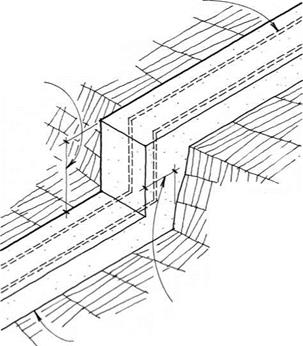
REBAR continuous THRouGH STEp


MULTIPLES OF 8 IN. FOR CONCRETE-BLOCK FOUNDATION WALL (MAX. DEPTH 2A IN.)


11/2-IN. By 3-in.
(Approx.) KEyWAy
locks footing
to cast-in-
place concrete
foundation wall.


concrete foundation wall


backfill


horizontal rebar
per local code
drainpipe
SEE 18A


note

keep cut in soil
AS vertical
AS possible
AT step in
footing.


locate bottom
of footing
on level,
undisturbed
soil below
frost line.


note

use KEyWAy footings oNLy
with concrete foundation

WALLS WHERE LATERAL LoADS on

foundation are not significant.
use footings doweled with
vertical rebar for lateral loads.


min. width equals depth of footing.


locate bottom of footing on level, undisturbed soil below frost line.


FOOTING WITH KEYWAY


STEPPED FOOTING


About the drawingsAbout the drawingsAbout the drawingsAbout the drawings

About the drawings

Code requirements for rebar use may vary, but a few rules of thumb can be helpful guidelines. Verify with local codes first.

Sizes—Rebar is sized by diameter in Vs-in. incre­ments: #3 rebar is 3/8-in. dia., #4 is Уг-in. dia., #5 is 5/8-in. dia., etc. The most common sizes for wood-frame construction foundations are #3, #4, and #5.

Overlapping—Rebar is manufactured in 20-ft. lengths. When rebar must be spliced to make it contin­uous or joined at corners, the length of the lap should equal 30 bar diameters, as shown below.

30 BAR DIAMETERS

t——- —f


EDGE OF MASONRY FiREBOX


tie firebox TO

FOOTING AT

corners with

REBAR Dowels.

verify with local codes.


6-iN. (MiN.) PROJECTiON BEYOND FIREBOx

or chimney masonry


12-iN. (MiN.) DEpTH

without rebar


tie fireplace & foundation FOOTING with REBAR.


Clearance—The minimum clearance between rebar and the surface of the concrete is 3 in. for footings, 2 in. for formed concrete exposed to backfill or weather, and 3/4 in. for formed concrete protected from the weather.


locate BOTTOM of footing below FROST line.


FIREPLACE FOOTING


REBAR RULES OF THUMB


About the drawingsAbout the drawings

Column footings (also called pier pads) support col­umns in crawl spaces and under porches and decks. Place all footings on unfrozen, undisturbed soil free of organic material. The bottom of the footing must be located below the frost line unless it is within a crawl space. Columns may need to be anchored to column footings to prevent uplift caused by wind or earthquake forces (see 6B).

Typical sizes are 12 in. to 14 in. for square footings or 16-in. to 18-in. diameter for round footings.

Extreme loads may require oversize footings. The vertical load divided by the soil bearing capacity equals the area of footing, e. g.,

6,000 lb. – 2,000 psf = 3 sq. ft.

To prevent moisture in the footing from damaging the column, use a pressure-treated wood column or place a 30-lb. felt moisture barrier between an untreated wood column and a concrete footing, or use steel connectors where required (see 6B).

A COLUMN FOOTINGS

About the drawings

I 44

L


About the drawings

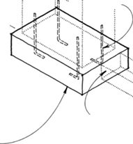
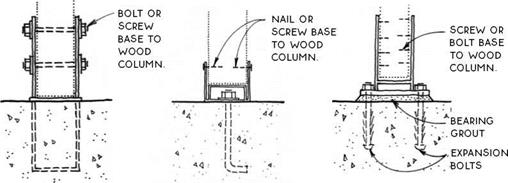
Подпись: Wet Base THIS GALVANIZED STEEL BASE MUST BE PRECISELY LOCATED IN WET CONCRETE. AVAILABLE WITH STANDOFF TO RAISE THE WOOD COLUMN ABOVE THE CONCRETE.

Single Strap

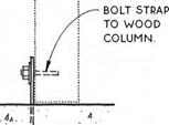
GALVANIZED STEEL STRAP IS OFTEN USED IN CRAWL SPACES OR UNDER PORCHES.

NOTE

USE PT. WOOD COLUMN OR PLACE 30-LB. FELT MOISTURE BARRIER BETWEEN UNTREATED POST & CONCRETE.

Adjustable Base

MULTIPLE-PIECE GALVANIZED STEEL ASSEMBLY ALLOWS FOR SOME LATERAL ADJUSTMENT BEFORE NUT IS TIGHTENED. BASE ELEVATES WOOD COLUMN ABOVE CONCRETE FOOTING.

Drilled Base

EXPANSION BOLTS ARE DRILLED INTO FOOTING OR SLAB AFTER CONCRETE IS FINISHED. ALLOWING FOR PRECISE LOCATION OF COLUMN.

NOTE

EXPANSION BOLTS REQUIRE SPECIAL INSPECTION IN MOST JURISDICTIONS

COLUMN BASE CONNECTORS

About the drawings

Подпись: FOUNDATION WALLS Concrete & Concrete Block
About the drawings

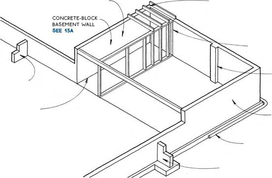
Foundation walls act integrally with the footings to support the building. They also raise the building above the ground. The primary decision to make about foun­dation walls is what material to make them of. There are several choices:

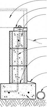
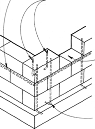
Concrete block—Also known as concrete masonry unit or CMU construction, concrete block is the most common system for foundation walls. Its primary advantage is that it needs no formwork, making it appropriate in any situation, but especially where the foundation is complex. Concrete masonry will be used most efficiently if the foundation is planned in 8-in. increments, based on the dimensions of standard con­crete blocks (8 in. by 8 in. by 16 in.).

Cast concrete—Concrete can be formed into almost any shape, but formwork is expensive. The most eco­nomical use of cast concrete, therefore, is where the formwork is simple or where the formwork can be used several times. Cast-in-place concrete is used for forming pier and grade-beam systems, which are especially appropriate for steep sites or expansive soils (see 13).

Reinforcing—Some local codes do not require rein­forcing of foundation walls. Codes in severe earthquake zones are at the other extreme. As a prudent minimum,
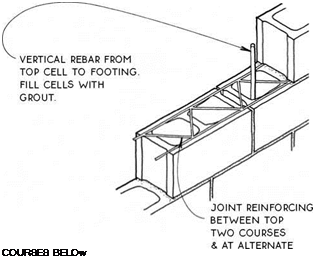
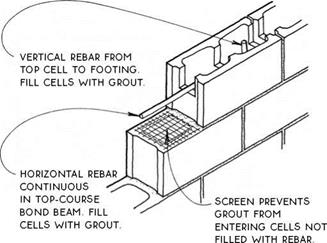
all foundation walls should be tied to the footing with vertical rebar placed at the corners, adjacent to all major openings, and at regular intervals along the wall. There should be at least one continuous horizontal bar at the top of the wall. Joint reinforcing may be an ade­quate substitute (see 10B).

Width—The width of the foundation wall depends on the number of stories it supports and on the depth of the backfill, which exerts a lateral force on the wall. With minimum backfill (2 ft. or less), the width of the wall can be determined from the chart below.

The design of basement walls and foundation walls retaining more than 2 ft. of backfill should be verified by an engineer or an architect.

The minimum height of a foundation wall should allow for the adequate clearance of beams and joists from the crawl-space floor. A code-required 18-in. clearance usually requires 12-in. to 24-in. foundation walls, depending on the type of floor system.

r NO. OF STORIES

FOUNDATION WIDTH

1

6 in.

2

8 in.

2

10 in.

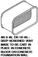
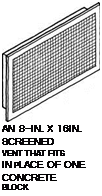
Подпись: AN 8-iN. OR 10-IN.- DEEP SCREENED VENT MADE TO BE CAST IN PLACE IN CONCRETE BLOCK OR CONCRETE FOUNDATION WALL Подпись: AN 8-IN. X 16IN. SCREENED VENT THAT FITS IN PLACE OF ONE CONCRETE BLOCK Подпись: ONE OF vARIOuS pLASTIC OR METAL VENTS MADE TO VENT THROUGH THE RIM JOIST AND FASTEN TO wOOD SIDING. CARE MuST BE TAKEN TO INSTALL PROPER FLASHING Moisture— Even with the best drainage, the soil under crawl spaces always carries some ground mois­ture, which will tend to migrate up to the crawl space in the form of vapor. This vapor can be substantially controlled with a vapor retarder laid directly on the ground, which must first be cleared of all organic debris. Crawl-space vapor retarders should be 6-mil (min.) black polyethylene. The dark plastic retards plant growth by preventing daylight from reaching the soil. Adding a concrete rat slab over the vapor retarder will enhance its effectiveness and durability.

Moisture cannot be allowed to build up in a crawl space where it can create catastrophic damage caused by mildew, fungus, and other organisms dependent on moisture. There are two basic strategies to remove the moisture – ventilation to the outside, and conditioning the air as part of the air volume inside the building.

In both cases, air is moved through the crawl space to replace moisture-laden crawl-space air.

Ventilation—Crawl-space cross ventilation minimizes the buildup of excess moisture under a structure. In some regions, crawl-space ventilation is also required to remove radon gas.

The net area of venting is related to the under-floor area and to the climatic and groundwater conditions. Most codes require that net vent area equals У150 of the under-floor area with a reduction to У1500 if a vapor barrier covers the ground in the crawl space. Screened vents should be rated for net venting area.

Vents should supply cross ventilation to all areas of the crawl space. Locating vents near corners and on opposite sides of the crawl space is most effective.

Access doors can provide a large area of ventilation. Wells allow vents to be placed below finished grade.

As shown in the drawing above right, screened vents are available for installing in masonry, cast concrete, and wood. They are available in metal or plastic, and some have operable doors for closing off the crawl space during winter to conserve heat. Operable vents should be closed only during extreme weather con­ditions. Closing the vents for an entire season will increase moisture in the crawl space and can signifi­cantly increase the concentration of radon gas.

A CRAWL-SPACE CONTROLS_______

Unvented crawl space – In climates with humid summer weather, ventilation actually brings moisture into a crawl space, where hot, humid air contacts cooler surfaces in the crawl space and condenses there. The best solution in this case is to insulate the crawl space, close it up tight, and heat and cool it as if it were another room. It doesn’t add much to the heating or cooling load, being a small volume with little exterior wall area. This strategy is also appropriate in other climates.

Unvented crawl spaces must be insulated at the foundation wall. The insulation can be installed using the same details as for a basement wall (see 15C). Care must be taken to seal the space well against air infiltra­tion. This includes sealing the joint between foundation wall and mudsill (see 12A) and sealing the joints of the floor assembly that bears on the mudsill (see 33-34).

Pests—Rodents and other large burrowing pests can be kept out of crawl spaces by means of a “rat slab,” which is a 1-in. to 2-in.-thick layer of concrete poured over the ground in a crawl space. A concrete-rated moisture barrier should be placed below this slab (see 20). Termites and other insect pests are most effectively controlled by chemical treatment of the soil before con­struction begins.

Radon—Radon is an odorless radioactive gas that emerges from the ground and is present at very low concentrations in the air we breathe. This gas can build up to dangerous levels when trapped in a crawl space (or basement). Although present everywhere, radon concentration levels in the earth are higher in some regions, and all of North America has been mapped and evaluated for radon danger. The best protection against radon buildup is to ventilate the crawl space well and/or effectively seal the ground below the building. Radon test kits are readily available.

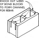
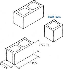
About the drawingsПодпись: Bond or Lintel CUT HALF, CORNER, AND OTHER BLOCKS ON SiTE TO CONTiNUE BOND BEAMS TO THE END OF WALLS AND AROUND CORNERS. Подпись: CornerПодпись: iN.About the drawingsAbout the drawings

Stretcher or Regular

STANDARD WiDTHS ARE 35/8 iN.,

55/8 iN., 75/8 iN., 95/8 iN., AND 115/8 iN. ALL DiMENSiONS ARE ACTUAL.

Jamb

JAMB BLOCKS ARE AVAiLABLE iN HALF (SHOWN) AND STRETCHER SiZES. iN ONE SiDE A SLOT LOCKS BASEMENT WiNDOWS iN PLACE.

NOTE

ALMOST ANY SiZE OR SHAPE OF MASONRY WALL CAN BE BUiLT WiTH BASiC BLOCK TYPES. CONSULT NCMA FOR CONSTRUCTiON TECHNiQUES AND FOR SPECiAL BLOCKS WiTH SPECiAL EDGE CONDiTiONS, TEXTURES, COLORS, AND SiZES.

(A CONCRETE-BLOCK TYPES


About the drawings

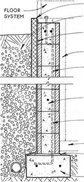
FLOOR SYSTEM

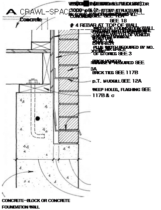
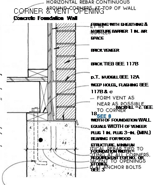
P. T. MUDSiLL SEE 12A

BOND BEAM WiTH # 4 REBAR AT TOP COURSE OR BELOW VENT OPENiNG. FOR JOiNT­REiNFORCiNG ALTERNATiVE SEE 10B

BACKFiLL

VERTiCAL REBAR


BLOCK FOR VENT OMiTTED AS NEAR AS POSSiBLE TO CORNER SEE 8A


FULL MORTAR BASE WHERE LATERAL LOADS APPLY

SLOPE TOP OF FOOTiNG WiTH MORTAR.

DRAiNAGE SEE 18A


VERTiCAL REBAR AT CORNER, ADJACENT TO OPENiNGS & iN CELLS CONTAiNiNG ANCHOR BOLTS


FOOTiNG


CRAWL-SPACE FOUNDATION WALL

Concrete Block


CORNER & VENT OPENING

Concrete-Block Foundation Wall


About the drawingsAbout the drawings

NOTE

Подпись: NOTE TO REINFORCE A JOINT, A wELDED HEAVY-WIRE TRUSS MAY BE SUBSTITUTED FOR HORizONTAL REBAR IN MANY CASES. IT IS EMBEDDED IN THE MORTAR jOiNTS BETwEEN COURSES OF MASONRY. Подпись: COURSES BELOw About the drawings

Подпись: CONCRETE-BLOCK FOUNDATION Joint-Reinforcing Alternative
Подпись: CONCRETE-BLOCK FOUNDATION Rebar Placement

HORiZONTAL REBAR SHOULD BE CONTiNUOUS iN A BOND BEAM AT THE TOP COURSE, OR AT THE SECOND COURSE iF FOUNDATiON VENTS ARE LOCATED iN THE TOP COURSE. HORiZONTAL REBAR MAY ALSO BE LOCATED iN Intermediate BOND Beams If THE HEiGHT, wiDTH & Function OF THE wALL REQUIRE IT.

About the drawings

BOND-BEAM TOp COURSE wiTH reinforcing SEE 10A

BOND OR LINTEL BLOCKS wiTH GROUT AND REBAR OR REINFORCED CAST- CONCRETE LINTEL vertical REBAR AT BOTH SIDES of opening AND extended INTO FOOTING

CORNER AND HALF

blocks at side jambs

About the drawings

CONCRETE-BLOCK BASEMENT

Opening within Wall

CONCRETE-BLOCK BASEMENT

Opening at Top of Wall

About the drawings
About the drawings

BRICK-VENEER FOUNDATION

Brick below Mudsill
brick-veneer foundation

Brick Level with Mudsill

About the drawingsAbout the drawings

1/2-iN. STEEL ANCHOR BOLT AT 4 FT. OR 6 FT. O. C.

(MAX.) & 12 iN. (MAX.) FROM END OF EACH PiECE OF MUDSiLL. verify wITH LOcAL CODES.

1/2-iN. STEEL NUT WITH STEEL WASHER

2X4 OR 2X6 P. T. WOOD MUDSiLL

SILL GASKET OF CAULK OR FIBERGLASS AT BASEMENTS OR OTHER LIVING SPACE

CONTINUOUS

termite shield in termite regions

CONCRETE OR CONCRETE-BLOCK FOUNDATION WALL REBAR

7-IN. MiN. DEPTH OF ANCHOR BOLT INTO FOUNDATION WALL

NOTE

SOME CODES REQUIRE LONGER BOLTS FOR MASONRY WALLS.

BEND DOUBLE-STRAP ANCHOR AROUND MUDSiLL & NAIL AT SIDE & TOP, OR NAIL ONE STRAP TO MUDSiLL & OTHER TO FACE OF STUD.

2X4 OR 2X6 P. T. WOOD MUDSiLL

SILL GASKET OF CAULK OR FIBERGLASS AT HEATED SPACE

PLACE MUDSiLL ANCHORS INTO FRESH CONCRETE OR NAIL TO FORM BEFORE PLACING CONCRETE.

SLAB WITH TURNED – DOWN FOOTING SEE 22

NOTE

VERIFY ACCEPTABILITY OF MUDSiLL
ANCHOR WITH LOCAL BUILDING CODE.
THE MUDSiLL ANCHOR ALLOWS THE
ABILITY TO FINISH SLAB TO THE EDGE
BUT IT IS DIFFICULT TO USE WITH
TERMITE SHIELD.

MUDSILL WITH ANCHOR BOLT

MUDSILL WITH MUDSILL ANCHOR

A CRIB WALL IS AN ALTERNATIVE TO COLUMNS & A BEAM SUPPORT FOR JOISTS IN A CRAWL SPACE. IT ALLOWS MORE CLEARANCE FOR DUCTS AND EQUIPMENT & AVOIDS THE POTENTIAL PROBLEM OF CROSS-GRAIN SHRINKAGE IN BEAMS.

A PONY WALL IS USEFUL IN A STEPPED FOUNDATION WALL OR IN A SLOPING PIER & GRADE-BEAM FOUNDATION. THE PONY WALL PROVIDES A LEVEL SURFACE FOR CONSTRUCTION OF THE FIRST FLOOR.

Подпись:Подпись: FOUNDATION WALL OR GRADE BEAMAbout the drawingsПодпись: JOISTSПодпись: SINGLE TOP PLATEПодпись: CRIB STUDS PLACED DIRECTLY BELOW EACH JOISTAbout the drawingsПодпись: NOTE CRIB WALL IS BRACED BY PERIMETER FOUNDATION WALL.DOUBLE TOP PLATE CONTINUOUS WITH MUDSiLL

PONY WALL RECEIVES THE SAME EXTERIOR FINISH AS THE FRAMED WALL ABOVE.

Подпись: CRIB WALLPONY WALL

FOUNDATIONS

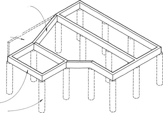
Pier & Grade-Beam Systems


NOTE

piER & grade-beam foundation systems

ARE particularly SuiTED TO ExpANSivE SOILS or steep hillsides. they are also useful TO avoid damaging nearby tree ROOTS. pier & GRADE-BEAM

SYSTEMS MuST BE ENGINEERED.


GRADE BEAM CAN SLOPE TO CONFORM TO CONTOUR


PONY WALL ON TOP OF GRADE BEAM MAKES A LEVEL SURFACE FOR FLOOR CONSTRUCTiON SEE 12D —


GRADE BEAM SEE 13C


pier SEE 13B


A PIER & GRADE-BEAM SYSTEMS


p. T. mudsill SEE 12A


GRADE BEAM SEE 13C

continuous pier

REBAR TIED TO GRADE BEAM

Backfill & DRAINAGE SEE 18A


continuous rebar

ENGINEERED & TIED TO pier REBAR

BACKFILL

drainpipe if required SEE 18A

FOAM CuSHION ALLOWS ExpANSivE SOIL TO RISE WITHOuT. U – V.. LIFTING FOuNDATION.

p. T. MuDSILL SEE 12A


SMOOTH top EDGE OF pier TO allow SOIL TO expand without

LIFTING piER.


continuous rebar

ENGINEERED & TIED to pier REBAR

BACKFILL

drainpipe if required SEE 18A

v-SHApE ALLOWS expansive SOIL TO RISE WITHOuT LIFTING

foundation.


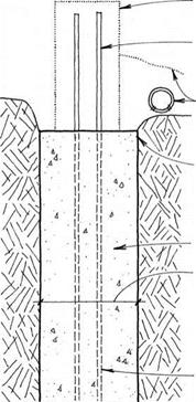
CAST CONCRETE piER

typical pier

DIAMETERS ARE 12 IN. TO 18 IN. SpACING varies & depths RANGE TO 20 FT., DESCENDING ON SOIL.

ENGINEER SizE & TYpE OF REBAR.


PIERS FOR GRADE BEAM


About the drawings

About the drawingsAbout the drawingsAbout the drawingsAbout the drawings

About the drawings

CONCRETE BASEMENT WALL SEE 15B


CONNECTiON TO WOOD FLOOR’

JOiSTS ON MUDSiLL SEE 33A & B JOiSTS FLUSH WiTH MUDSiLL SEE 33C & D JOiSTS BELOW MUDSiLL SEE 34


CONNECTiON TO STuD wALLS SEE 15D


pilaster SEE 16A


buttress SEE 17C


CONNECTiON TO CONCRETE Slab SEE 21C & D


waterproofing SEE 18C


NOTE

for basement walls, vERiFy thickness

Of CONCRETE OR CONCRETE BLOCK; SizE, AMOuNT, AND pLACEMENT OF REBAR; STRENGTH OF CONCRETE OR GROuT; AND CONNECTiON TO FLOOR SySTEMS WiTH AN ARCHITECT OR Engineer.


DRAINAGE SEE 18B


counterfort SEE 17A & B


About the drawings

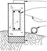
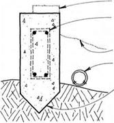
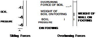
Retaining walls—Retaining walls resist lateral loads from the bottom only. They rely on friction at the base of the footing and soil pressure at the outside face of the footing to resist sliding. The weight of the wall and the weight of soil on the footing resist overturning.


About the drawings

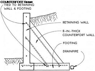
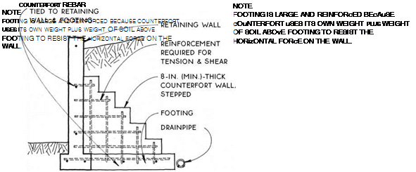
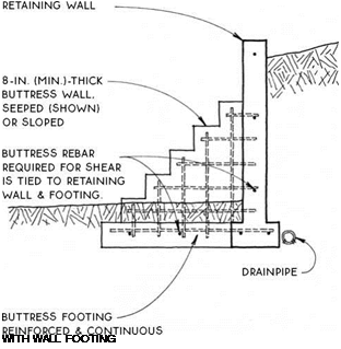
Buttresses and counterforts strengthen retaining walls in much the same way that pilasters strengthen basement walls (see 17). Buttresses help support retaining walls from the downhill side, and counterforts from the uphill side.

Technically, freestanding retaining walls are not a part of the building, but they are included here because they are typical extensions of the building components (foundation and basement walls) into the landscape.


^ BASEMENT & RETAINING WALLS


About the drawings

About the drawingsПодпись:Подпись:Подпись:Подпись:Подпись:Подпись:About the drawingsПодпись: о°л°0ОО§° О 00OLOQ0°Подпись:About the drawings

iNSULATiON SEE 15C

BACKFILL AND DRAiNAGE SEE 18B

WATERPROOFING SEE 18C

ALTERNATIVE LOCATION FOR INSULATION

VERTICAL REBAR PLACED AT TENSION SIDE OF WALL RESISTS BENDING FORCES.

BOND BEAMS

as required BY engineering

vertical rebar

ANCHORS wALL TO FOOTING.

SLAB SEE 21C OR D

full mortar joint on roughened

FOOTING

FOOTING SEE 4
insulation SEE 15C

backfill AND DRAINAGE SEE 18B

waterproofing SEE 18C

alternative location FOR insulation

vertical rebar placed at tension SIDE OF wall RESISTS BENDING FORCES.

horizontal rebar as required by

ENGINEERING

vertical REBAR ANCHORS wALL TO FOOTING.

SLAB

SEE 21C OR D

FOOTING SEE 4

About the drawings

About the drawings

BASEMENT WALL

Concrete Block

BASEMENT WALL

Concrete

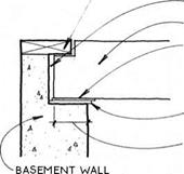
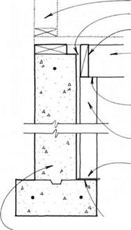
Подпись:About the drawingsПодпись: NOTE DO NOT uSE CONTINUOUS VAPOR BARRIER ON wARM SIDE OF wALL BELOW GRADE. SEE 18C Heated basements must be insulated at their perim­eter walls. The amount of insulation required depends on the climate. There are two ways to insulate base­ment walls—from the exterior or from the interior.

About the drawingsExterior—Exterior insulation should be a closed-cell rigid insulation (extruded polysty­rene or polyisocyanurate) that will not absorb moisture. This insulation, available in 2-ft. or 4-ft. by 8-ft. sheets, is attached directly to the basement wall with adhesive or mechanical fasteners. It may be applied either under or over the waterproofing, depending on the type.

Interior—Interior insulation may be either rigid or batt type. Petroleum-based rigid types must be covered for fire protection when used in an interior location. Other rigid insulation, such as rigid mineral fiber, need not be fire – protected. Building a stud wall with batt insu­lation has the advantage of providing a nailing surface for interior finishes.
About the drawings

BASEMENT iNSULATiON


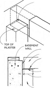
1/2-IN. air space at end

OF WOOD BEAM OR USE p. T. WOOD OR STEEL


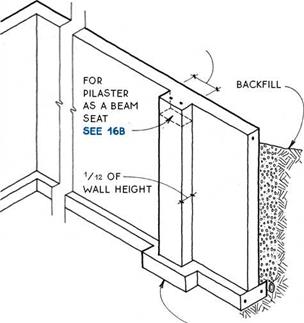
1/10 OF THE DiSTANCE BETWEEN VERTiCAL SUPPORTS (OTHER PiLASTERS, CORNERS, OR WALLS)


NOTE

USE LAMINATED WOOD OR STEEL BEAM TO MINIMIZE SHRINKAGE.


1/2-in. air space


BEAM


30-LB. FELT UNDER BEAM AT pOINT OF CONTACT WITH CONCRETE OR CONCRETE BLOCK

SHIMS TO LEVEL BEAM

3-IN. MINIMUM BEARING SURFACE FOR WOOD BEAM


NOTE

proportions for pilaster dimensions are approximate. rebar in wall, pilaster & FOOTING must BE engineered.


footing SEE 4


pilaster


About the drawings About the drawings

FRAMED WALL

1/2-in. air space

BLOCKING AS REQUIRED

BEAM WITH 1V2-IN. DECKING SEE 47C & D OR BEAM & JOIST SYSTEM SEE 33C

ATTACH BEAM TO COLUMN


1/2-IN. air space at

END AND SIDES OF WOOD BEAM OR USE p. T. WOOD OR STEEL


NOTE USE LAMINATED WOOD OR STEEL BEAM TO MINIMIZE SHRINKAGE.


NOTCH BEAM FOR MUDSILL IF REQUIRED (MAX. NOTCH EQUALS 1/4 DEpTH OF BEAM).


4X4 WOOD OR p. T. WOOD COLUMN

WOOD COLUMN BEARS ON FOOTING. IF ATTACHMENT IS REQUIRED SEE 6B


1/2-in. air space

BEAM

30-LB. FELT UNDER BEAM AT pOINT OF CONTACT WITH CONCRETE OR CONCRETE BLOCK

SHIMS TO LEVEL BEAM

3-IN. MINIMUM BEARING SURFACE FOR WOOD BEAM


30-LB. FELT UNDER COLUMN AT FOOTING OR USE p. T. WOOD


CONCRETE OR CONCRETE-BLOCK FOUNDATION WALL


BEAM POCKET


WOOD-COLUMN BEAM SUPPORT

Basement or Crawl-Space Wall


Concrete or Concrete Block


About the drawingsAbout the drawingsAbout the drawingsAbout the drawingsAbout the drawings

About the drawings

NOTE

Подпись:

Подпись: COUNTERFORT REBAR About the drawings

About the drawings

Подпись: 0 CONCRETE COUNTERFORT Подпись: CONCRETE-BLOCK COUNTERFORT

COUNTERFORT MUST BE pROFESSIONALLY ENGiNEERED. REiNFORCEMENT iS REQUiRED FOR TENSiON AND SHEAR.

NOTE

Подпись: WITH WALL FOOTING

BUTTRESS & RETAINING WALL MUST BE PROFESSIONALLY ENGINEERED.

BUTTRESS

Concrete or Concrete Block

Choosing a foundation

Each foundation system has many variations, and it is important to select the one best suited to the climate, the soil type, the site, and the building program. With all foundations, you should investigate the local soil type. Soil types, along with their bearing capacities, are often described in local soil profiles based on informa­tion from the U. S. Geological Survey (USGS). If there is any question about matching a foundation system to the soil or to the topography of the site, consult a soil or structural engineer before construction begins. This small investment may save thousands of dollars in future repair bills.

design checklist

Because the foundation is so important to the longevity of the building and because it is so difficult to repair, it is wise to be conservative in its design and construc­tion. Make the foundation a little stronger than you think you need to. As a minimum, even if not required by code, it is recommended that you follow this rule-of – thumb checklist:

1. Place the bottom of the footing below the frost line on solid, undisturbed soil that is free of organic mate­rial. (Local codes will prescribe frost-line depth.)

2. Use continuous horizontal rebar in the footing and at the top of foundation walls (joint reinforcing may be allowable in concrete-block walls). Tie the footing and wall together with vertical rebar.

3. Tie wood members to the foundation with bolts or straps embedded in the foundation. Anchoring require­ments in hurricane and severe earthquake zones are shown in the following chapters, but specific require­ments should be verified with local codes.

4. Provide adequate drainage around the foundation. Slope backfill away from the building and keep soil

6 in. below all wood.

Many codes and many site conditions require mea­sures beyond these minimum specifications. In addi­tion, there are several other considerations important
to a permanent foundation system, and these are dis­cussed in this chapter. They include support of loads that do not fall at the perimeter wall, such as footings for point loads within the structure and at porches and decks; insulation and moisture barriers; waterproofing and drainage; protection against termites, other insects and wood-decaying organisms; and precautions against radon gas.

5. Get the details right. Use pressure-treated or other decay-resistant wood in contact with concrete. Straps, hangers, and fasteners in contact with pres­sure-treated lumber should be hot-dip galvanized to protect against degradation from the preservative chemicals. Use a moisture barrier between all con­crete and untreated wood.

other foundation systems

The permanent wood foundation (PWF), developed in the 1970s, now accounts for about 5% of founda­tions in the United States and 20% in Canada. Made of pressure-treated framing, the crawl-space or base­ment walls sit on a bed of compacted gravel rather than a concrete footing. The same framing crew that constructs the structure above can build the founda­tion walls; and when insulation, wiring, and other utili­ties are required, they can be located in wall cavities between studs as they are in the rest of the building.

Insulating concrete formwork (ICF) may be used in place of wooden formwork for the walls of a basement or heated crawl space. The insulation stays in place after the concrete walls have been poured and provides thermal separation for the space within. ICF walls must be protected on the exterior, and wiring and other utili­ties must be either integrated or carved into the inte­rior insulation surface.

Foundations

A

foundation system has two functions. First, it supports the building structurally by keeping it level, minimizing settling, preventing uplift from the forces of frost or expansive soils and resisting horizontal forces such as winds and earthquakes. Second, a foundation system keeps the wooden parts of the building above the ground and away from the organisms and moisture in the soil that both eat wood and cause it to decay.

The foundation is the part of a building that is most likely to determine its longevity. If the foundation does not support the building adequately, cracks and openings will occur over time, even in the most finely crafted structure. No amount of repair on the structure above the foundation will compensate for an inadequate foundation; once a foundation starts to move significantly, it will continue to move. We now have developed the knowledge to design and construct durable foundations, so there is no reason to invest in a modern building that is not fully supported on a foun­dation that will endure for the life of the structure.

In the United States, there are three common foun­dation types. Each performs in different ways, but all rely on a perimeter foundation, i. e., a continuous support around the outside edge of the building.

slab-on-grade foundations

Slab-on-grade systems are used mostly in warm climates, where living is close to the ground and the frost line is close to the surface. The footing is usually shallow, and the ground floor is a concrete slab. Many slab-on-grade systems allow the concrete footing, foundation, and subfloor to be poured at the same time.

crawl spaces

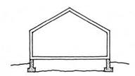
Crawl spaces are found in all climates but predominate in temperate regions. In this system, the insulated wooden ground floor is supported above grade on a foundation wall made of concrete or concrete block. The resulting crawl space introduces an accessible zone for ductwork, plumbing, and other utilities, and allows for simple remodeling.

basements

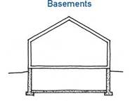
Basements are the dominant foundation system in the coldest parts of the country, where frost lines mandate deep footings in any case. Like crawl spaces, basements are accessible, and in addition they provide a large hab­itable space. Basement foundation systems are usually constructed of concrete or concrete-block foundation walls. Drainage and waterproofing are particularly crit­ical with basement systems.

Slab-on-Grade Foundation

Foundations


Crawl Spaces

Foundations


Foundations

Подпись: 2FOUNDATIONS

A final note

My intention in writing and now in twice revising this book has been to assist designers and builders who are attempting to make beautiful buildings that endure. With the drawings, I have tried to describe the relationship among the parts of every common connection. Alternative approaches to popular details have been included as well. I have relied primarily on my own experiences but have also drawn significantly on the accounts of others. In order to build upon this endeavor, I encourage you, the reader, to let me know of your own observations and critical comments.

Please send them to me care of The Taunton Press,

PO. Box 5506, Newtown, CT 06470-5506 or via email to thallonarch@continet. com.

A focus on durability

Although the details in this book have been selected partly on the basis of their widespread use, the primary focus is on durability. I believe that wood-frame buildings can and should be built to last for 200 years or more. To accomplish this, a building must be built on a solid foundation; it must be designed and built to resist moisture; it must be protected from termites, ants, and other insect pests; it must be structurally stable; and it must be reasonably protected from the ravages of fire. All these criteria may be met with standard construction details if care is taken in both the design and the building process.

There are some accepted construction practices, however, that I do not think meet the test of durability. For example, the practice in some regions of building foundations without rebar is not prudent. The small investment of placing rebar in the foundation to minimize the possibility of differential settlement is one that should be made whether or not it is required by code. The stability of a foundation affects not only the level of the floors but also the integrity of the structure above and the ability of the building to resist moisture. Another common practice that I discourage is the recent overreliance on caulks and sealants for waterproofing. This practice seems counterproductive in the long run because the most sophisticated and scientifically tested sealants are warranted for only 20 to 25 years. Should we be investing time, money, and materials in buildings that could be seriously damaged if someone forgets to recaulk? It is far better, I believe, to design buildings with adequate overhangs or with flashing and drip edges that direct water away from the structural core by means of the natural forces of gravity and surface tension.

Durability, however, does not depend entirely upon material quality and construction detailing. Durability also depends heavily upon the overall design of the building and whether its usefulness

over time is sufficient to resist the wrecking ball. The more intangible design factors such as the quality of the space and the flexibility of the plan are extremely important but are not a part of this book.

on codes

Every effort has been made to ensure that the details included in this book conform to building codes. Codes vary, however, so local codes and building departments should always be consulted to verify compliance.

how the book works

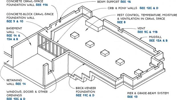
The book’s five chapters follow the approximate order of construction, starting with the foundation and working up to the roof (however, the last chapter on stairs is intentionally out of sequence). Each chapter begins with an introduction that describes general principles. The chapters are divided into subsections, also roughly ordered according to the sequence of construction. Subsections, usually with another more specific introduction and an isometric reference drawing, lead to individual drawings or notes.

Subsections are called out at the top of each page for easy reference. Each drawing has a reference letter, a title, and often a subtitle. Sometimes a reference and title is assigned to an entire topic. With this system, all the drawings (and topics) may be cross-referenced. The callout “see 42A”, for example, refers to drawing A on page 42.

As many details as possible are drawn in the simple section format found on architectural working drawings. Most are drawn at the scale of 1 in. equals 1 ft. or 1У2 in. equals 1 ft., although the scale is not noted on the drawings. This format should allow the details to be transferred to architectural drawings with minor adjustments. (Details will usually have to be adjusted to allow for different size or thickness of material, for roof pitch, or for positional relationships.) Those details that are not easily depicted in a simple section drawing are usually drawn isometrically in order to convey the third dimension.

Any notes included in a detail are intended to describe its most important features. By describing the relationship of one element to another, the notes sometimes go a little further than merely naming an element. Materials symbols are described on page 226. Abbreviations are spelled out on page 227.

The scope of the book

To provide a detailed reference, the scope of the book had to be limited. I decided to focus on the parts of a building that contribute most significantly to its lon­gevity. Virtually all the drawings, therefore, describe details relating to the structural shell or to the outer protective layers of the building. Plumbing, electrical, and mechanical systems are described only as they affect the foundation and framing of the building. Interior finishes and details are not covered because they are the subject of a companion volume, Graphic Guide to Interior Details (The Taunton Press, 1996). The process of construction, covered adequately in many references, has here been stripped away so as to expose the details themselves as much as possible. Design, although integral with the concerns of this book, is dealt with only at the level of the detail.

The details shown here employ simple, standard materials. With this type of information, it should be possible to build a wood frame building in any shape, at any size, and in any style. Many local variations are included.

Introduction

L

ight wood-frame construction originated in this country over 150 years ago and quickly evolved into the predominant construction system for houses and other small-scale buildings. Today, over 90% of all new buildings in North America are made using some version of this method. Remodeling projects follow the same track.

There are many reasons why this system has been the choice of professional and amateur builders alike over the years. A principal reason is its flexibility. Because the modules are small, virtually any shape or style of building can be built easily with the studs, joists, and rafters that are the primary components of wood-frame construction. In addition, the pieces are easily handled, the material is readily available, and the skills and tools required for assembly are easily acquired.

Given the popularity of the system, it was surprising to find that, before the publication of the first edition of this book, there existed no detailed and compre­hensive reference focusing on light wood framing.

Now, seventeen years and two editions later, over 275,000 copies of Graphic Guide to Frame Construction have found their way into the libraries of architects, contractors, owner-builders, and students.

The acceptance of the Graphic Guide as a standard reference has corresponded with great strides in building technology. Wood frame buildings today are built faster, stronger, and with more efficient use of materials. Engineered lumber products, relatively rare just 20 years ago, are now more common than sawn lumber for many parts of a building. Wooden buildings are now greatly more resistant to the forces of hurricanes and earthquakes. Vinyl windows, which were just being introduced, are now the standard. Advanced framing that both conserves material and allows for upgraded insulation is rapidly gaining acceptance. These and many other advances were incorporated into the second edition, but the building culture is not static. Best practices are evolving rapidly because of improved communication and building science, and innovative materials are proliferating to meet increased demand.

This third edition expands on those issues covered in the first two editions with the addition of the most recently developed practices and materials.

In particular, this edition updates the details for engineered lumber products and takes a closer look at the important issue of moisture in wood frame building assemblies. These two subjects have dominated the research in recent years and significantly impact each chapter of the book. The topic of environmental responsibility, which has gained serious traction in recent years, has been covered extensively in previous editions but receives further discussion here.

With all the attention given to advanced practices and materials, it is also important not to forget traditional principles and materials. These form the backbone of the system of wood frame construction and are the starting point for the important and considerable work of remodeling and renovation.