|
|
|
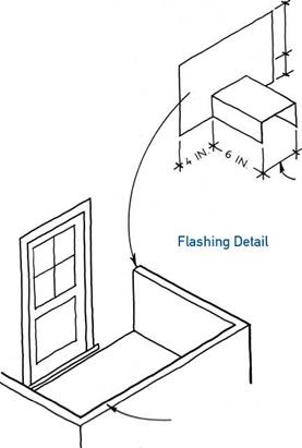
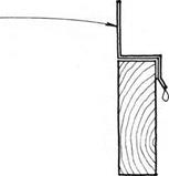
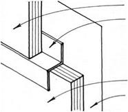
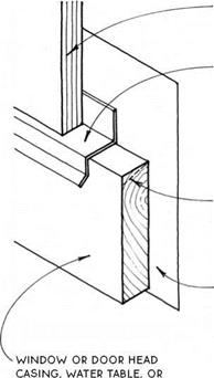
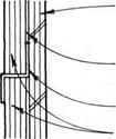
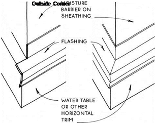
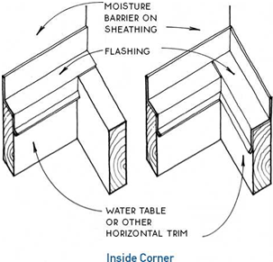
this horizontal joint is best protected with A flashing made to fit over the sheathing and moisture BARRIER of THE framed wall.
|
|
|
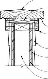
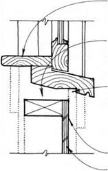
wood cap with sloped top
p. t. furring screwed to underside of wood cap
|
|
|
DRIP
trim fastened through siding to furring & WALL
siding
moisture barrier continuous over top of wall
sheathing
WALL FRAMING
|
|
|
|
|
note
this detail has a continuous moisture
BARRIER oVER THE TOP oF THE WALL WITHouT penetrations. the moisture BARRIER MAy BE replaced with metal flashing.
|
|
|
|
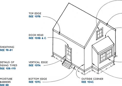
Many of today’s common exterior wall finishes have been protecting walls from the weather for hundreds of years. Others such as plywood, hardboard, and vinyl have been developed more recently. Regardless of their history, when applied properly, each is capable of protecting the building for as long as the finish material itself lasts.
If possible, the best way to protect both the exterior finish and the building from the weather is with adequate overhangs. But even then, wind-driven rain will occasionally get the building wet. It is important, therefore, to detail exterior wall finishes carefully at all but the most protected locations.
The introduction of effective moisture barriers under the siding has the potential to prolong the life of walls beyond the life of the siding alone. While the siding is still the first line of defense against weather, it is possible to view one of its primary functions as keeping sunlight from causing the deterioration of the moisture barrier, which ultimately protects the walls of the building.
Where the moisture barrier stops—at the edges and the openings through the wall—special attention must be paid to the detailing of exterior wall finishes.
Sealants—In this country alone, there are more than 200 manufacturers of 20 different types of caulks and sealants. However, the appropriate use of sealants for wood-frame buildings is limited for two reasons. First, sealants are not really needed—there are 200-year-old wooden buildings still in good condition that were built without the benefit of any sealants. Second, the lifespan of a sealant is limited—manufacturers claim only 20 to 25 years for the longest-lasting sealants. Therefore, it is best practice to not rely heavily on the use of sealants to keep water out of buildings.
However, some situations in wood-frame construction do call for the use of a sealant or caulk. These are mostly cases where the sealant is a second or third line of defense against water intrusion or where it is used to retard the infiltration of air into the building. In all instances, it is recommended that the caulk or sealant not be exposed to the direct sunlight.
@ EXTERIOR WALL FINISHES
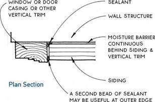
A VERTICAL EDGE IS A LIKELY PLACE FOR WATER TO LEAK AROUND THE EXTERIOR WALL
finish into the structure of a building. a continuous moisture barrier behind the vertical joint is crucial. a sealant can help deter the moisture, but will deteriorate in the ultraviolet light unless placed behind the wall finish,
WHERE IT WILL BE PRoTEcTED.
AT THE upper edges of WALL FINisHEs (AT eaves & rakes, under windows & doors & at other horizontal breaks), direct moisture away from the top EDGE of THE finish MATERIAL To THE face of the wall.
 |
|
if siding is to be painted.
|
|
|
|
|
|
|
|
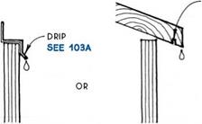


the bottom edge of the wall finish is more
LIKELY to GET WET THAN THE TOP. ALLoW WATER
to fall from the bottom edge of the wall finish in a way that avoids capillary action.

6
porch
: .. or deck
I
I
! s
foundation roof
or other
MATERIAL
EXTERIOR WALL FINISHES
At Bottom Edges
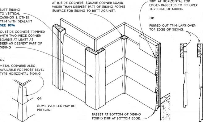


Horizontal wood siding is common in both historic and modem buildings. The boards cast a horizontal shadow line unique to this type of siding.
Materials—Profiles (see below right) are commonly cut from 4-in., б-in., and 8-in. boards. Cedar, redwood, and pine are the most typical. Clear grades are available in cedar and redwood. Many profiles are also made from composite hardboard or cementboard. These materials are much less expensive than siding milled from lumber and are almost indistinguishable from it when painted.
A HORIZONTAL SIDING
Drop Shiplap T & G Bevel
Horizontal Siding Profiles
Types—Siding joints may be tongue and groove, rabbeted, or lapped. Common profiles (names may vary regionally) are illustrated at bottom right.
Application—Boards are typically applied over a moisture barrier and sheathing, and should generally be back-primed before installation. Boards are face – nailed with a single nail near the bottom of each board but above the board below to allow movement. Siding is joined end to end with miter or scarf joints and sealant over a stud.
Finish—Horizontal wood siding is usually painted or stained. Clear lumber siding is sometimes treated with a semitransparent stain.
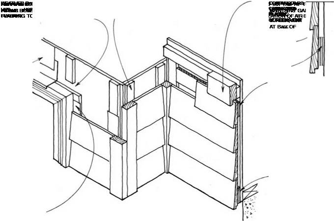
Rain Screen Siding—Rain screen siding strategy recognizes that some moisture will penetrate the wall and provides an easy path for this moisture to escape the wall assembly. A rain screen wall can be understood as two layers of protection with an air space in between.
An outer layer sheds most of the weather, and an inner layer takes care of what little moisture gets through.
The critical element—one that is not present in (most) other siding systems—is the air space between the two layers. This air space provides a capillary break and promotes the rapid escape of moisture with a clear path to the base of the wall for water to drain by gravity and by allowing ventilation to remove moisture in the form of water vapor.
Materials—The inner layer can be made of the same materials as the moisture barrier in most siding systems: tar paper, building wrap, or rigid foam insulation in conjunction with flashing (and tape or sealant). The air space is created by vertical furring strips, usually 3/8 in. to У2 in. thick aligned over the studs. The
outer layer is usually made with horizontal wood siding (clapboards), but can be made of any material that sheds water and is capable of spanning between the vertical furring strips. Screening is required at the top and bottom of the wall to keep insects out of the air space.
Application—Materials are applied with nails or staples as with standard siding materials. Special care should be taken that materials lap properly to shed water. The inner layer, called the drainage plane, must be especially carefully detailed and constructed to keep moisture out of the framing. Back-priming and endpriming of wood siding materials is very important to prolong the life of the material and of the finish.
Finish—Rain screen siding can be finished with any paint or stain designed for use on standard siding. Because the system breathes and does not trap moisture within the wall, finishes will typically outlast the same finish applied to a standard wall.

@ RAIN SCREEN SIDING
trim may BE ELIMINATED at horizontal TOP


 EDGES If SIDING IS OIT cAREFuLLY TO FIT UNDER SILLS OR EAVES.
OR
 matched SIDING MAY BE TRIMMED
with second
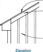
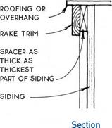

LAYER, OR BOARD SIDING WITH HORIZONTAL BATTEN.
top edges (soffit trim, eave TRIM & under SILLS) TRIMMED WITH under SILL TRIM INTO WHicH SIDING SLIDES. SPEQAL TooL


 punches tabs at cut top
EDGE oF SIDING; TABS Lock
into trim, which may need to be furred depending on location of horizontal cut
IN SIDING.
Vinyl sidings were developed in an attempt to eliminate the maintenance required of wood sidings. Most aluminum-siding manufacturers have moved to vinyl.
Material—There are several shapes available. Most imitate horizontal wood bevel patterns, but there are some vertical patterns as well. Lengths are generally about 12 ft., and widths are 8 in. to 12 in. The ends of panels are factory-notched to allow for lapping at end joints, which accommodates expansion and contraction. Color is integral with the material and ranges mostly in the whites, grays, and imitation wood colors. The vinyl will not dent like metal, but will shatter on sharp
impact, especially when cold. Most manufacturers also make vinyl soffit material, and some also make decorative trim. Vinyl produces extremely toxic gasses when involved in a building fire.
Installation – Vinyl has little structural strength, so most vinyl sidings must be installed over solid sheathing. Proper nailing with corrosion-resistant nails is essential to allow for expansion and contraction. Because vinyl trim pieces are rather narrow, many architects use vinyl siding in conjunction with wood trim, as suggested in the isometric drawing above.
@ VINYL SIDING
|
TOP EDGES ARE SOMETIMES LEFT WITHOUT TRIM BECAUSE THEY CAN EASILY BE CUT TO A CLEAN SQUARE EDGE THAT IS BUTTED AGAINST A SoFFIT, EAvE, or other horizontal surface, or trim may be added.
|
|
|
horizontal joints between siding PANELS oR between PANELS & oTHER MATERIAL SHoULD BE blocked if they do not occur over a plate or floor framing.
|
|
|
LAP PANELS To FoRM A DRIP EDGE oR
|
|
|
BUTT PANELS AND FLASH WITH METAL z FLASHING,
SEE 104A
|
|
|
vertical joints BETWEEN SIDING PANELS SHoULD ALWAYS FALL ovER A STUD.
|
|
|

manufactured
LAP joiNT
|
|
|
butt joint covered
WITH BATTEN
|
|
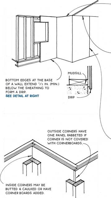



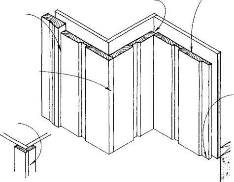
Materials— Plywood siding is available in 4-ft.-wide panels, 8 ft., 9 ft., and 10 ft. tall. Typical thicknesses are 3/s in., V’2 in. and 5/s in. The panels are usually installed vertically to avoid horizontal joints, which require blocking and flashing. Textures and patterns can be cut into the face of the plywood to resemble vertical woodsiding patterns.
Installation—Manufacturers suggest leaving a Vs-in. gap at panel edges to allow for expansion. All edges should be treated with water repellent before
installation. It is wise to plan to have window and door trim because of the difficulty of cutting panels precisely around openings. Fasten panels to framing following the manufacturer’s recommendation.
Single-wall construction—Since plywood, even in a vertical orientation, will provide lateral bracing for a building, it is often applied as the only surface to cover a building. This is called single-wall construction and has some unique details (see 80 and 113).
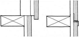
Most of the details for double-wall plywood construction also apply to single-wall construction. But with single-wall construction, the moisture barrier is applied directly to the framing, making it more difficult to achieve a good seal. The wide-roll, polyolefin mois – ture/air infiltration barriers work best (see 88B). Also, the bottom edge of the plywood is flush against the foundation, so a drip detail is impossible (see right).
Flashing—Windows and doors that are attached through the casing and need head flashing because of exposure to rain or snow are very difficult to flash. As shown in the drawings below, a saw kerf must be cut into the siding at the precise location of the flashing. The flashing and siding must be installed simultaneously before the door or window is attached.
 Flashing a Header

|
COVER HORIZONTAL EDGES WITH TRIM FASTENED TO A SPACER. LOCATE SHINGLE FASTENERS VERY HIGH ON LAST cOuRSE
|
|
|
NOTE
SHORT HORIZONTAL EDGES SUCH AS APRONS MAY BE COVERED WITH A PIECE OF TRIM FASTENED TO THE SLOPED SURFACE OF THE SHINGLES. FOR RAKE TRIM. SEE 115A & B
|
|
|
FASTENERS 1 IN. (MIN.) ABOVE COURSE LEVEL OF NEXT COURSE
|
|
|
shingles
butt TO
VERTICAL
TRIM
|
|
|
JOINTS BETWEEN SHINGLES OFFSET 11/2 IN. (MIN.) FOR THREE ADJACENT COURSES.
|
|
|
1A-IN. SPACE BETWEEN ADJACENT SHINGLES IN FIELD (NOT AT CORNERS OR EDGES)
|
|
|
DOUBLE
BOTTOM
COURSE
PROJECTS
1/2 IN. BELOW
SHEATHING TO
FORM DRIP.
|
|
|
OUTSIDE CORNERS ARE WOVEN SO ALTERNATE ROWS HAVE EDGE OF SHINGLE EXPOSED.
EDGE IS TRIMMED FLUSH WITH ADJACENT SHINGLE ON OPPOSITE FACE OF CORNER. CORNER BOARDS CAN ALSO BE USED AS TRIM AT OUTSIDE CORNERS. SEE 110 .
|
|
|
INSIDE CORNERS ARE WOVEN LIKE OUTSIDE CORNERS.
SHINGLES ARE TRIMMED TO BUTT AGAINST SHINGLE ON OPPOSITE FACE. TOP SHINGLE ALTERNATES FROM ROW TO ROW. CORNERBOARDS CAN ALSO BE USED AS TRIM AT INSIDE CORNERS. SEE 110
|
|
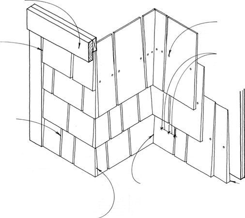

Shingles are popular because they can provide a durable, low-maintenance siding with a refined natural appearance. Shadow lines are primarily horizontal but are complemented with minor verticals. Material costs are relatively moderate but installation costs may be very high.
Materials—Shingles are available in a variety of sizes, grades, and patterns. The most typical is a western red cedar shingle 16 in. long. Redwood and cypress shingles are also available. Because shingles are relatively small, they are extremely versatile, with a wide variety of coursings and patterns.
Installation—Shingles are applied over a moisture barrier to a plywood or OSB wall sheathing so at least two layers of shingles always cover the wall. Standard
coursing allows nail or staple fasteners to be concealed by subsequent courses. With shingles there is less waste than with other wood sidings.
Finish—Enough moisture gets between and behind shingles that paint will not adhere to them reliably.
Left unfinished, they endure extremely well, but may weather differentially, especially between those places exposed to the rain and those that are protected.
Stains and bleaching stains will produce more even weathering.
Preassembled shingles—Shingles are also available mounted to boards. These shingle boards increase material cost, decrease installation cost, and are most appropriate for large, uninterrupted surfaces. Corner boards are required at corners.
@ WOOD SHINGLE SIDING
|
|
|
|
|
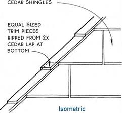
SECOND PIECE OVERLAPS FIRST.
|
|
|
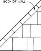
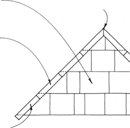
START AT BOTTOM OF RAKE WITH BOARD RIPPED TO THIcKNESS
of butt end of shingles. TOP END is cut level & FITS uNDER SHINGLE (SEE ISOMETRIc AT RIGHT).
|
|
|
|
|
ONE Method OF FINISHING THE TOP EDGE OF A SHINGLE wALL IS TO LAP THE SHINGLE cOuRSES wiTH TRIM PIEcES RIPPED FROM A cEDAR 2x. IF THE cOuRSING IS EQuAL, ALL THE TRIM PIEcES, ExcEPT FOR THE MITERED TOP PIEcES, wILL ALSO BE EQuAL.
|
|
|
|
|
THE BASE Layer IS NOT ExPOSED & THEREFORE
can be a lower-grade
SHINGLE.
|
|
|
FINISH-LAYER SHINGLE
projects about 1/2 IN.
BELOw BASE LAYER TO FORM A DRIP.
|
|
|
RIP SHINGLES TO DESIRED wIDTH & APPLY AT SAME cOuRSING AS
|
|
|
NAILING MuST BE EXPOSED FOR THIS cOuRSING.
|
|
|
NOTE
FOR PREPAINTED OR PRIMED SHINGLES, LEAVE NO SPAcE BETwEEN FINISH LAYER SHINGLES.
|
|
|
DOuBLE cOuRSING, AN ALTERNATIVE cOuRSING METHOD, cALLS FOR TwO LAYERS APPLIED AT THE SAME cOuRSE. A PREPAINTED OR PRIMED SHINGLE cALLED SIDEwALL SHAKE IS cOMMONLY uSED.
|
|
|
|

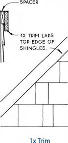
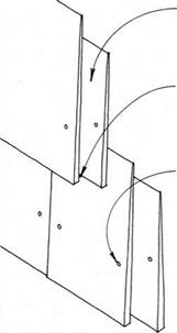

SHINGLE SIDING AT RAKE
DOUBLE-COURSED SHINGLES
Shingled & IxTrim


Brick veneer covers wood-frame construction across the country. Where it is not subjected to moisture and severe freezing, it is the most durable exterior finish.
Materials—Bricks come in a wide variety of sizes, with the most common (and the smallest) being the modular brick (2>4 in. by 35/s in. by 75/s in.). These bricks, when laid in mortar, can follow 8-in. modules both horizontally and vertically. Colors vaiy from cream and yellows to browns and reds, depending on the clay color and method of firing. Bricks should be selected for their history of durability in a given region.
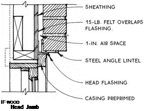
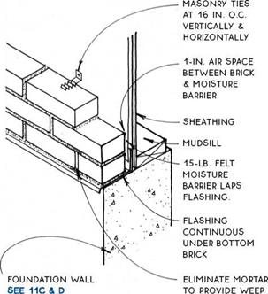
Installation— Bricks are laid in mortar that should be tooled at the joints to compress it for increased resistance to the weather. Because both brick and mortar are porous (increasingly so as they weather over the years), they must be detailed to allow for ventilation and drainage of the unexposed surface. A 1-in. air space between the brick and the wood framing, with weep holes located at the base of the wall, typically suffices (see 117B). It is important to keep this space and the weep holes clean and free of mortar droppings to ensure proper drainage.
TOP OF WALL IS DETAILED TO KEEP WATER OFF THE HORIZONTAL SuRFAcE OF THE TOP BRIcK. THIS cAN
usually be accomplished with the detailing OF
THE ROOF ITSELF. cOvER THE JOINT BETWEEN BRIcK & ROOF WITH WOOD TRIM. cAuLK THE jOINT AS FOR vERTicAL jOINTS, BELOW.
|
SEALANT BETWEEN WOOD & BRIcK
|
RAKE IS uSuALLY TRIMMED WITH WOOD
sufficiently WIDE TO cover the stepping OF brick caused BY SLOPE. DETAIL AS FOR TOP OF WALL.
|
SHEATHING AIR SPAcE brick
BAcKER ROD SEALANT
vertical casing OR
TRIM OF WOOD OR OTHER MATERIAL
|
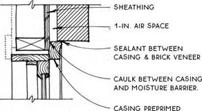
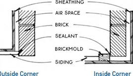
vERTicAL jOINTS Such AS WINDOW & DOOR cASINGS AND AT TRANSITIONS TO OTHER MATERIALS MuST BE cAREFuLLY cAuLKED TO SEAL AGAINST THE WEATHER. BAcKPRIME WOOD cOvERED BY OR
in contact with brick.
Finish – A number of clear sealers and masonry paints can be applied to the finished masonry to improve weather resistance, but reapplication is required eveiy few years.
@ BRICK VENEER
|
BOTH INSIDE & OUTSIDE CORNERS CAN BE MADE SIMPLY WITH THE BRICKS THEMSELVES.
|
|
 |
|
|
|
IF WooD
|
|
|
|
|
|
|
|



sill preprimed on underside if wood
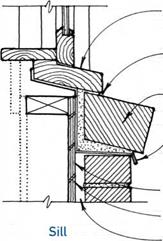
sealant between SILL and brick.
rowlock brick sloped at angle of SILL
FLASHING coNTINuouS to back of SILL
SHEATHING 15-LB. FELT 1-IN. AIR SPAcE
CONTROL JOINT ORIENTED HORIZONTALLY OR VERTICALLY &
LOCATED OVER STRUCTURAL MEMBERS & DIAPHRAGMS BREAKS STUCCO PANELS INTO 18-FT. (MAX.) DIMENSIONS (OR LENGTH-TO-WIDTH RATION OF 2.5И). ——
SELF-FURRING GALVANIZED 17-GAUGE 11/2-IN. MESH STUCCO WIRE (SHOWN) OR GALVANIZED EXPANDED METAL LATH
15-LB. FELT BOND BREAK
Stucco is made of cement, sand, and lime. It is usually applied in three coats, building to a minimum thickness of 3/4 in. Cost may be moderate in areas with high use, but high where skilled workers are few.
Materials— Reinforcing materials through which the plaster is forced are either stucco wire or metal lath. This reinforcing is fastened either to sheathing or directly to the framing (without sheathing). When sheathing is used, it must be rigid enough to remain stiff during the process of applying the stucco—5/s-in. plywood is typical.
A double-layer moisture barrier between the reinforcing and the framing is important because the stucco will bond with the outer layer of barrier, destroying its ability to repel water. The outer layer forms a bond
break so that the inner layer will remain intact to protect the framing. The inner layer performs best if it is thick, with drainage channels.
Application – The first (scratch) coat has a raked finish, the second (brown) coat has a floated finish, and the final (color) coat may have a variety of finishes. Applying stucco takes skill, so stucco is the least appropriate of all the exterior wall finishes for owner-builders to attempt.
Finish—Textures ranging from smooth to rustic are achieved by troweling the final coat. Color may be integral in the final coat or may be painted on the surface. Stucco is not very moisture resistant and must be sealed or painted.



 CASING BEAD AT TOP,
SIDE, OR RAKE EDGES
OR
WRAPPED BASE COAT WITH FIBERGLASS MESH
FINISH COAT WITH INTEGRAL COLOR
BASE COAT WITH EMBEDDED FIBERGLASS MESH
RIGID INSULATION
with grooved back
OR

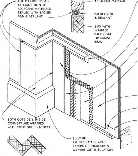
Synthetic stucco looks like traditional stucco but is really a flexible acrylic coating applied over rigid insulation. Called EIFS (Exterior Insulation and Finish
Systems), synthetic stucco is more flexible than standard stucco and more moisture resistant. This moisture resistance, which certainly is a strength of the system, worked against early versions of its application when imperfect detailing led to moisture being trapped inside the wall behind the impermeable EIFS layer. With updated water-managed EIFS, it is now assumed that some moisture will penetrate the surface, and therefore a drainage path is provided for this moisture to escape.
Materials—There are several manufacturers of water – managed EIFS. Each starts with rigid insulation, fastened to the framing with nails fitted with large plastic washers designed to prevent crushing of the insulation. The insulation is protected from impact by a stucco
base made of acrylic cement reinforced with fiberglass mesh. An acrylic finish coat with integral color provides moisture protection.
Application—All systems start with an effective moisture barrier applied to the wall sheathing. The next layer is a drainage plane that provides a clear path for moisture to escape. This drainage plane can be a separate plastic drainage mat or vertical grooves integrated into the back side of the rigid insulation, which is the following layer. The base coat of stucco is troweled directly onto the insulation, reinforced with mesh, and then another layer of base coat. The final coat is troweled over the hardened base coat.
Finish—There are a variety of common troweled finish textures. Color is integral in the final coat, so painting is unnecessary, but inspection and repair of sealant joints every few years is highly recommended.
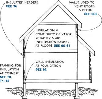
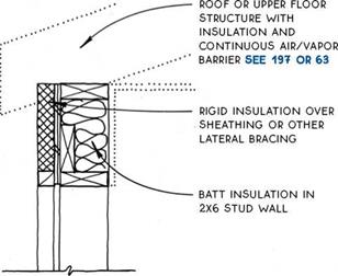
 Wall insulation is typically provided by fiberglass batts. Building codes in most climates allow 2×4 walls with ЗУ2 in. of insulation (R-ll) or 2×6 walls with 5V2 in. of insulation (R-19).
Vapor retarder—Vapor retarders are installed in conjunction with wall insulation. The purpose of a vapor retarder, a continuous membrane located on the warm side of the insulation, is to prevent vaporized (gaseous) moisture from entering the insulated wall cavity, where it can condense, leading to structural or other damage.
Common vapor retarders include 4- or 6-mil polyethylene film applied to the inside of framing or specially formulated paint or primer applied to the surface of chywall.
Rigid insulation with taped
, , , RETARDER WARM
joints may also be used.
Various vapor retarder materials have different rates of permeability (see 88A), and, because moisture can enter a wall assembly from either side, it is wise to use the most permeable material proven to be effective in a given region so as not to trap moisture within the assembly.
The vapor retarder should always be located on the warm side of the insulation. In a cold, chy climate the
retarder goes on the inside of the wall. But in mixed climates the migration of vapor can reverse in the summer. For this reason, building scientists recommend against using low-permeability materials on the inside of air-conditioned walls.
The location of the vapor barrier may be adjusted in upgraded applications provided that two-thirds or more of the insulative value of the wall remains to the cold side of the barrier.
АІГ barrier— An air barrier is intended to control the migration of air through the insulated envelope of a building. Standard construction practices allow voids and breaks in the building envelope that can leak up to two times the total air volume of the building per hour—accounting for up to 30% of the total heat loss (or gain) of the building. Upgrading the envelope can cut this air leakage to one-third of an air change per hour and can thus have significant consequences for energy bills in most climates.
An effective air barrier combines a continuous membrane with tight seals around openings such as windows where the membrane is penetrated. It may be made of a variety of materials and may be located either inside or outside of the insulation. When inside the insulation, the barrier may be chywall, rigid insulation, or the same film that forms a vapor retarder. Outside the insulation, building wrap, rigid insulation, or sheathing may be used. In each case, joints are taped or overlapped and caulked, and tight seals are made with floor and ceiling air barriers. Windows, doors, electrical, plumbing, and other services that penetrate the membrane are sealed with expansive foam, caulk, and/or special tape.
It is important to consider that the reduced ventilation rate due to control of air leakage can lower indoor air quality. The provision of controlled ventilation with simple energy-saving devices such as air-to-air heat exchangers can alleviate this problem.
 Unfaced batts—The most common method of insulating walls is to use unfaced batts that are fitted between studs. A vapor retarder is applied to the warm side of the wall in the form of a vapor retarding paint or primer or a 4-mil polyethylene film. Properly detailed, this vapor retarder can serve as the air barrier.
Faced batts – Batt insulation is often manufactured with a paper facing that, in cold climates, serves as both vapor retarder and means of attachment. For attachment, the facing material has tabs that are stapled in place between the studs.
To use the facing as a vapor retarder, it is better to staple the tabs to the face of the studs to make a better seal. However, this interferes with the installation of interior finish materials because the tabs build up unevenly on the face of the studs.
Rigid insulation—In
standard construction, rigid insulation is generally used only in extreme situations where wall depth is limited but a code-prescribed R-value is required. Examples of such situations include headers (see 76A & B) and locations where heat ducts, vents, or plumbing must be in exterior walls. In upgraded framing systems, however, rigid insulation is used extensively (see 122A).
Spray-foam insulation—It can cost many times as much as competing insulations, but spray-foam insulation can equal the R-value of the best rigid foam, double as a vapor retarder, and fully fill the most awkwardly shaped framing cavity. Except for its high cost, it is a nearly ideal insulating material for mixed climates where warm and cold sides of the envelope reverse during the year.
In climatic zones with extremely cold or hot weather (or high utility rates), there is special incentive to insulate buildings beyond code minimums. A decision to super – insulate affects the construction of walls more than floors or roofs because walls are generally thinner (being constructed of 2x4s or 2x6s rather than 2x10s or 2x12s). Walls are also in direct contact with the ambient air because they do not have a crawl space or attic to intervene as a buffer.
The most direct way to increase the insulative capacity of walls is to make them thicker. A 2×4 framed wall upgraded to 2×6, for example, will increase from a combined (batt plus framing) R-value of 9.0 to a value of R-15.1. But increasing wall thickness alone is only effective to a point because a significant part of the wall (about 9% of a wall framed at 24 in. o. c.) is composed of studs, plates, etc., which conduct heat at about three times the rate of insulative batts. When headers and other extra framing are considered, walls often have as much as 20% of their area devoted to framing. The conductance of heat through this framing is called thermal bridging.
There are two strategies for decreasing the effects of thermal bridging. The first is to reduce the quantity of framing members and is called advanced framing (see 74). The second strategy is to insulate the framing members that remain so that they do not “bridge” between the cold and warm sides of the wall. Several ways to insulate framing members are discussed on the following pages.
Rigid insulation—Rigid insulation added to the exterior or interior of a framed wall can typically add an R-value of 7 to 14 at the same time that it interrupts thermal bridging (see 122).
Strapping—Horizontal nailing strips are attached to the inside of a stud wall. Insulative values of R-25 are easily attainable (see 123).
Staggered-stud framing—A double offset stud wall framed on a single, wide plate. Combined insulative values of R-30 are common (see 124).
Double wall framing—A duplicate (redundant) wall system with R-values of up to 40 is easily reached (see 125).




 single 2X6 top plate


 EDGES If SIDING IS OIT cAREFuLLY TO FIT UNDER SILLS OR EAVES.
 matched SIDING MAY BE TRIMMED


 punches tabs at cut top


 CASING BEAD AT TOP,


 Wall insulation is typically provided by fiberglass batts. Building codes in most climates allow 2×4 walls with ЗУ2 in. of insulation (R-ll) or 2×6 walls with 5V2 in. of insulation (R-19).
 Unfaced batts—The most common method of insulating walls is to use unfaced batts that are fitted between studs. A vapor retarder is applied to the warm side of the wall in the form of a vapor retarding paint or primer or a 4-mil polyethylene film. Properly detailed, this vapor retarder can serve as the air barrier.


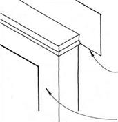


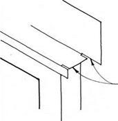
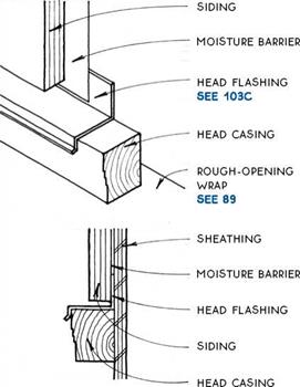
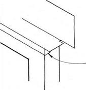
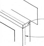


 CONTINUOUS HORIZONTAL Z METAL FLASHING WITH 2-IN. (MIN.) OVERLAPS At
 sheathing (OR stud wall for single-wall construction)


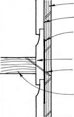 If a horizontal member must be connected to a wall in a location exposed to the weather, two things can be done to protect the structure of the wall. First, do not puncture the surface of the siding with the member, and do everything possible to attach the member to the surface of the siding with a minimum number of fasteners. Second, place an adequate gasket, such as 30-lb. or 90-lb. felt, behind the siding at the location of the attachment. This will help seal nails or screws that pass through the siding to the structure of the wall.
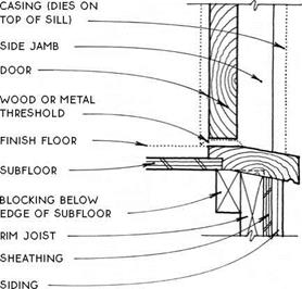
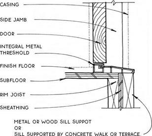


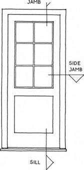
 Pocket doors – Pocket doors slide on a track attached to the head jamb and are sold as a kit, with the door and pocket separate and the pocket broken-down for ease of transport. The pocket is assembled at the site, and the head jamb (which much be set higher than 6 ft. 8 in. to allow for the track) is leveled, shimmed, and attached to the frame of the building. Next the pocket itself and the opposite jamb are shimmed and nailed. The heavier and wider the door and the better the quality of the hardware, the less likely the door is to derail. Pocket doors can’t be made to seal as tightly as hinged doors. The walls are flimsy at the pocket, and wiring or plumbing can’t be put in this section of wall.




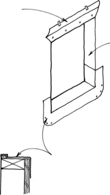

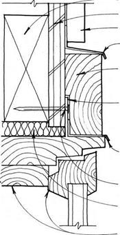
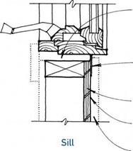
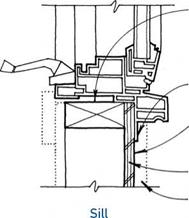
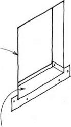 plastic or sheet-metal sill PAN provides alternative moisture protection in severe conditions. fasten pan only through sides and face flanges and lap sides with peel-and-stick flashing.
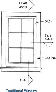
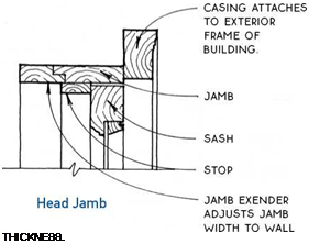
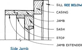
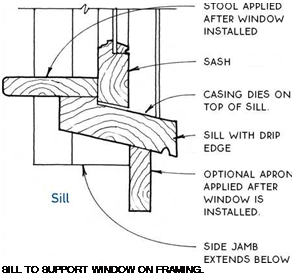 These components and their terminology have been handed down to the modern window, but modern windows are better insulated and better sealed, and usually need less maintenance than the traditional prototypes.
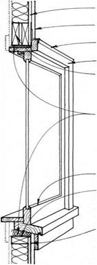

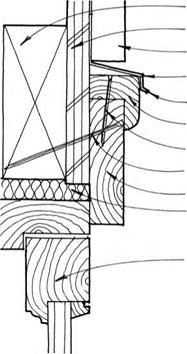
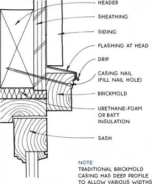
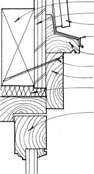
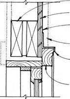
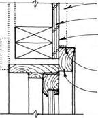
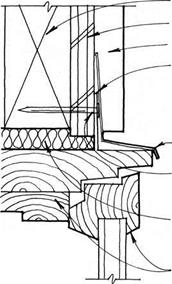
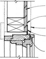
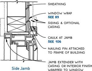
 Unclad wood windows are attached to the building through the casing. This is the traditional way that windows have been fastened to wood buildings. The nail holes are typically filled, and the casings painted. It is also possible to cover the nails with a dripmold or with a backband that may be nailed from the side or the face, depending on the profile of the backband. The backband is mitered at the corners and dies on the sill.


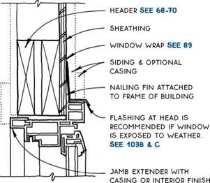 to frame of building

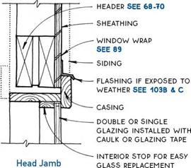
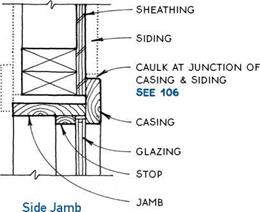
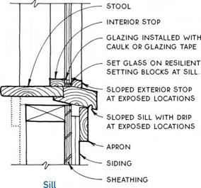 Where fixed windows are acceptable, a great deal of expense may be saved by custom-building the windows on the job without sash. In this case, the glass is stopped directly into the window frame, and caulk or glazing tape seals the glass to the casing just as it would to the sash. Ventilation must be provided for the space by means other than operable windows.