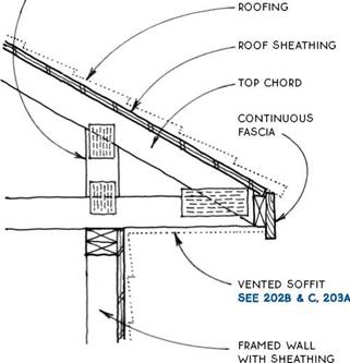
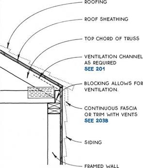
TRUSS WITH OVERHANGING EAVE
Exposed or Boxed-ln Eave
|
ENGINEERED HEEL TIED TO WEB SYSTEM OF TRUSS ALLOWS DEEP CEILING INSULATION SEE 198-199
|
|
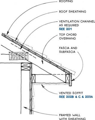
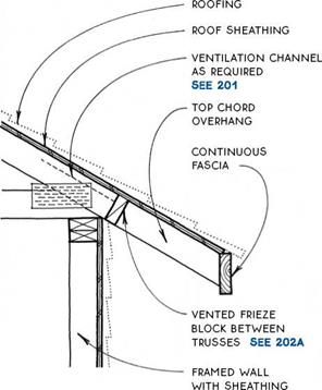
TRUSS WITH SOFFITED EAVE
TRUSS WITH SOFFITED EAVE
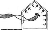
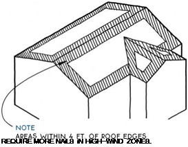
Because roofs are the highest part of a building and are the least weighted down by other parts of the building, they are the most vulnerable to the effects of wind. In areas prone to high winds, the design and detailing of roofs is one of the most critical concerns for the longevity of a building. The bracing of buildings to resist lateral wind forces is discussed in Chapter 3 (see 77 & 82).
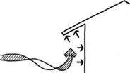
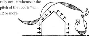
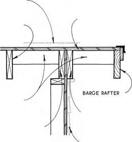
Wind generally moves horizontally to impose lateral forces on buildings, much as earthquakes do. But wind flows in complex shifting patterns around a building, creating pressures on some surfaces and suction on others. Thus it can create vertical forces that actually lift the roof off a building.
These vertical forces can be created in three ways. First, they may be produced as a negative pressure (suction) if developed on the leeward side of a building. In the case of a pitched roof, this condition theoreti-
A second way for wind to exert a vertical force on a roof is for the wind to catch a protrusion such as an eave or rake overhang. In this case, the force of the wind is localized at the edge of the roof.
Finally, wind can lift the roof structure from the inside of the building. This generally occurs as a weak point in the shell of the building such as a window or garage door giving way to the pressure of the wind. The wind suddenly enters the structure, pressurizing it and forcing the roof up.
To resist the force of high winds on roofs, several strategies may be employed. Some involve design decisions to minimize the impact of high winds in the first place, others involve strengthening what is built to minimize damage.
Design strategies—One basic strategy to increase a roof’s chance of survival in high winds is to keep the roof pitch low. High-pitch roofs extend higher into the sky, where wind velocity is greater, and present a greater surface area than do low-pitched roofs. Pitches between 2:12 and 7:12 are recommended for high-wind areas.
The shape of the roof also has a large impact on its durability in a windstorm. Generally, hip roofs fare the best because their geometry makes them self-bracing, and they have low eaves with no tall walls. Gable roofs present a weak point at the gable end itself, which is a tall vertical surface.
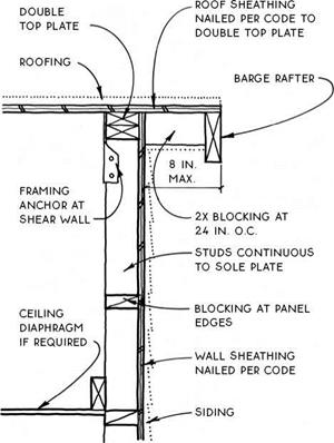
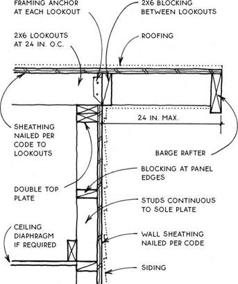
The width of overhangs at both eave and rake are important considerations for high-wind zones. Many buildings have been destroyed by winds that catch the underside of the eave and lift it off the building. Eaves of 8 in. or less are recommended for high-wind areas unless special measures are taken to anchor them.
Anchoring strategies—Assuming the building is shaped appropriately to withstand the force of high wind, it is still necessary to reinforce it beyond typical code standards. Framing members must be anchored to resist uplift and overturning, sheathing must be stronger, and fasteners must be increased. These measures are illustrated on the following page.
ROOF FRAMING FOR HIGH WIND

HIGH-WIND RAKE
Balloon Frame to Sheathing
HIGH-WIND RAKE
Balloon Frame with Lookouts
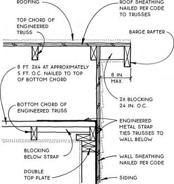


 NOTE
NOTE
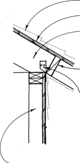
TOENAiLiNG (OR MORE FRAMiNG ANCHORS) TiE ROOF FRAMiNG TO DOUBLE TOP PLATE TO RESiST SHEAR FORCES PARALLEL AND PERPENDiCULAR TO WALL.
Platform Frame
Roof sheathing attaches to the surface of the rafters or trusses to form the structural skin of the roof.
It spans the rafters to support the roofing and, in the case of panel sheathing such as plywood or OSB, it acts with the walls to resist horizontal loads. Roof-sheathing material must be coordinated with the roofing itself, since each type of roofing has special requirements.
At exposed roof overhangs, the sheathing must be rated for exposure to the weather. The everyday sheathing used on the body of a roof is not rated for weather exposure, so when exposed eaves and/or rakes occur at the perimeter, a different (more expensive) weather-rated grade of plywood or OSB must be used. Solid board sheathing may also be used at these exposed locations.
The two basic types of sheathing are solid sheathing and open sheathing.
Solid Sheathing— Solid sheathing provides a continuous surface at the plane of the roof. This type of sheathing is necessary for composition roofing and built-up roofing, which have no structural capacity themselves. Metal, tile, and shingle roofing may also be applied to solid sheathing. For economic and structural (lateral-load) reasons, solid sheathing is almost always plywood, OSB, or other structural panels (see 163).
The structural panels act as a diaphragm to transfer lateral loads at the plane of the roof to the walls. When an exposed ceiling is desired, solid sheathing may
also be constructed of solid-wood tongue-and-groove boards. Tongue-and-groove sheathing, however, does not act as a diaphragm, so other methods of providing lateral-load stability, such as diagonal bracing, must be employed.
Open sheathing—Open sheathing, also called skip sheathing, is composed of boards spaced apart (see 166). This type of roof sheathing is used under wood shingles and shakes, which usually require ventilation on both sides of the roofing material. Open sheathing may also be chosen for economic reasons, but only if used with roofing systems such as metal or tile, which have the structural capacity to span between sheathing boards. Alternative methods of providing a roof diaphragm, such as diagonal bracing, must be used with open sheathing.
Combinations, of course, are also possible and often appropriate. For example, solid sheathing at exposed overhangs is often combined with open sheathing on the rest of the roof.
Recommendations—Sheathing recommendations for roofs by roofing types are as follows:
Composition and built-up roofing must be applied to solid sheathing because these roofing materials do not have the structural capacity to span between the boards of open sheathing.
Wood shingle and shake roofing is best applied over open sheathing because the spacing between the open sheathing allows the roofing to breathe from both sides, prolonging its life. Shingle and shake roofs may also be applied to solid sheathing at exposed eaves and rakes and similar locations. In some regions, the common practice is to place a moisture barrier over open sheathing to keep out wind-driven rain. In very windy areas, solid sheathing is often used. Consult with local codes and builders for the accepted practice.
Metal and tile roofing may be applied to either solid or open sheathing. Both roofing materials have the strength to span across open sheathing, but there is no advantage for either in having them breathe from both sides.
 ROOF SHEATHING
Introduction
NOTE


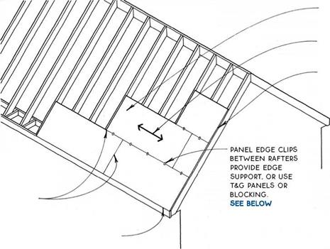
 most manufacturers specify a 1/8-in. space
BETWEEN THE EDGES OF pANELS TO ALLOW FOR
expansion. panels sized
FOR THIS Spacing ARE AVAILABLE. the gap may BE OMITTED IN VERY DRY climates., check WITH local codes & builders FOR accepted practice IN your area.
Panel installation—Low cost and ease of installation make plywood or OSB panels the sheathing of choice for most modern roofs. The system provides a structural diaphragm and is appropriate for all but wood shingle or shake roofing, which requires ventilation.
The standard panel size is 4 ft. by 8 ft., so rafter or truss spacing that falls on these modules is most practical. Care must be taken to protect panel edges from the weather by the use of trim or edge flashing (see 169C). Sheathing at exposed overhangs must be exterior or exposure 1-rated and must be thick enough to hold a nail or other roof fastener without penetration of the exposed underside.
Recommended fastening—Recommended fastening is 6 in. o. c. at edges and 12 in. o. c. in the field (6 in. in the field for supports at 48 in. o. c.). For sheathing spans greater than 24 in., tongue-and – groove edges, lumber blocking, or panel edge clips are required at edges between supports. Use two clips for spans of 48 in.
|

12 / 0 5/i6 in. 12 in.
16 / 0 5/i6 in. to 3/8 in. 16 in.
24 / 0 3/8 in. to У2 in. 24 in.
32 / 16 15/32 in. to 5/8 in. 32 in.
48 / 2 4 23/32 in. to 7/8 in. 48 in.
|
Notes—Values in the table above are based on APA – rated panels continuous over two or more spans with the long dimension of the panel perpendicular to supports. Verify span with panel rating. (For the APA rating stamp, see 48.)
Spans are based on a 30-lb. live load and 10-lb. dead load, the minimum rated by the APA—The Engineered Wood Association. Check local codes and with design professionals for higher loading such as greater snow loads or higher dead loads of concrete tiles or other heavy roofing. These ratings are minimum. For a more solid roof, reduce spans or increase thickness.
|
SOLID ROOF SHEATHING
Plywood & Non-Veneered Panels
|
|

NOTE


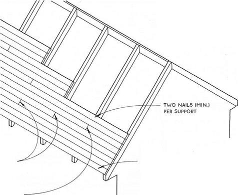
JOiNTS MAY BE MADE AT MiD-SPAN FOR SOME END-MATCHED DEckiNG. VERiFY NAiLiNG WiTH MANUFACTURER’S SpEcS. TOENAiLiNG AT MiDspan iS REquiRED for longer spans. VERiFy with manufacturer.
T&G sheathing (decking) is most often used for exposed ceiling applications. It can also be used selectively at exposed eaves or overhanging rakes. Rafters are spaced at wide centers since the decking will span more than 24 in. in most cases (see the table at right). Because this sheathing material does not provide a diaphragm at the plane of the roof, other means of bracing the roof against horizontal loads must usually be employed. For example, the roof may be braced with metal straps applied to the top of the sheathing or with a layer of plywood or OSB over the decking.
Insulation for an exposed ceiling must be located above the sheathing. Insulation will vary with climate and with roofing material. Rigid insulation is usually the most practical because of its thin profile, but it is more expensive than batt insulation. Batts are often chosen for colder climates, where the thickness of either type
|
EXPOSED T&G DECKiNG SPANS 1
|
|
Nominal thickness
|
Approximate span
|
|
2 in.
|
6.0 ft.
|
|
3 in.
|
10.5 ft.
|
|
4 in.
|
13.5 ft.
|
|
5 in.
|
17.0 ft.
|
of insulation (rigid or batts) requires adding a second level of structure above the decking to support the roof.
This table assumes a 30-lb. live load for Douglas – fir or southern pine species. The table is for comparison and approximating purposes only. The actual span capacity depends on roof pitch, species, live-load values, and end-joint pattern.
 SOLID ROOF SHEATHING
Exposed T&G Decking


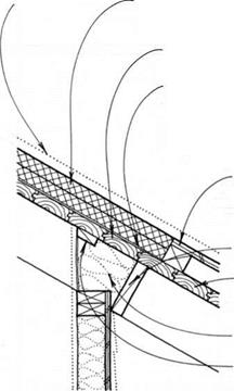


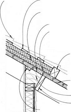
RIGID INSULATION OVER TEMPERATURE-CONTROLLED SPACE
T&G EXPOSED DECKING
insulation frieze block
NAILING BLOcK FOR FINISH wALL


Metal or composition roofing may be applied directly over rigid insulation on T&G sheathing. For this construction, fasteners must be sized to penetrate through the insulation but not through the decking.
Preformed metal roofing—Preformed metal roofing may be applied directly to the insulation over a layer of 15-lb. or 30-lb. felt. If the insulation is more than ЗУ2 in. thick, wooden nailers equal to the thickness of the insulation and parallel to the decking are recommended to provide a stable surface for roof fasteners. Nailers should be located 3 ft. to 5 ft. o. c., depending on the profile of the metal roofing.
Composition roofing—Composition roofing may also be applied directly if the insulation board is strong enough to withstand the rigors of the roofing process. Most asphalt-shingle manufacturers, however, will not honor their warranty unless the shingles are applied to a ventilated roof. Unventilated shingles can get too hot and deteriorate prematurely. The addition of vertical furring strips and sheathing over the insulation with vents at the top and bottom of the assembly will satisfy the requirement for ventilation.
EXPOSED T&G DECKING AT EAVE
Metal or Composition Roof
Wood or tile roofing requires another layer of material over the insulation. In some cases, it may be more economical to substitute nonrigid insulation.
Wood shingles or shakes—Wood shingles and shakes last longer it they are allowed to breathe from both sides, so they should be raised on furring strips above the level of the insulation. The furring strips may be nailed through the rigid insulation to the decking, or they may be attached directly to the decking between rows of insulation. The spaces and cracks between the shakes or shingles will usually provide adequate ventilation.
Despite the advantages of breathing, shingles should be installed over solid sheathing and underlayment in areas with extreme wind-driven rain or snow or if the roof pitch is as low as 3-in-12 or 3l/2-in-12.
Ceramic or concrete tiles—Ceramic and concrete tiles, like shingles, commonly require furring strips.
The furring strips should be spaced according to the length of the tiles (see 187B, 188, and 189).
EXPOSED T&G DECKING EAVE
Wood or Tile Roof
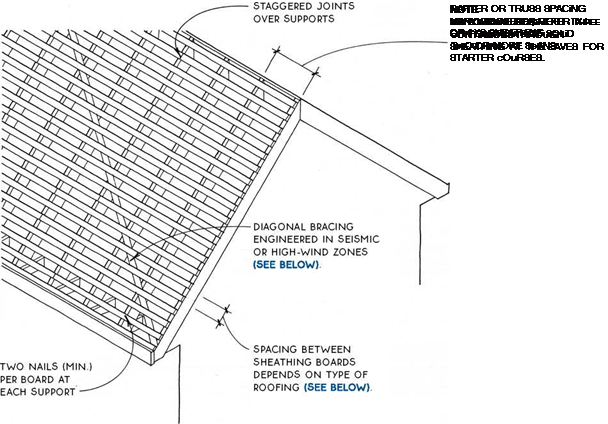
Open, or skip, sheathing is usually made with 1×4 or 1×6 boards nailed horizontally to the rafters with a space between the boards. Since this sheathing material does not provide a diaphragm at the plane of the roof, other means of bracing the roof against horizontal loads must be employed. Let-in wooden bracing or metal strap bracing applied to the top or bottom surface of the rafters will suffice in most cases. This bracing must be engineered in seismic or high-wind zones or for very large roofs. Bracing may sometimes be omitted on hip roofs because the shape of the roof provides the bracing.
Spacing for open sheathing depends on the type of roofing. The ability of the sheathing to span between
supports depends on the spacing and on the type of roofing applied over it. Check with local codes and with roofers for accepted local practices.
Wood shingles or shakes require spacing equal to the exposure of the shingles or shakes—usually about 5 in. for shingles to 10 in. for shakes. The sheathing is usually 1×4.
Concrete tiles, depending on the type, may be installed on open sheathing spaced in the 12-in. to 14-in. range. The roofing material is heavy, so 1×6 or 1×8 or 2×4 sheathing is practical.
Preformed metal roofing is lightweight and runs continuously in the direction of the rafters. In most cases, 1×6 sheathing at 24 in. o. c. is adequate.
@ OPEN ROOF SHEATHING
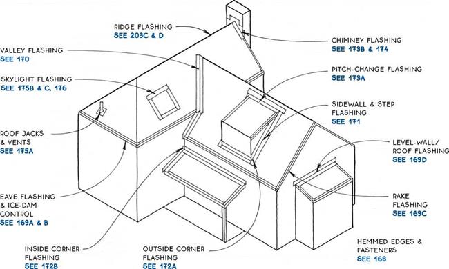
Flashing is a necessary component of most roofing systems. Flashing makes the roof watertight at edges, openings, and bends in the roof where the roofing material cannot perform the job alone.
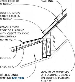
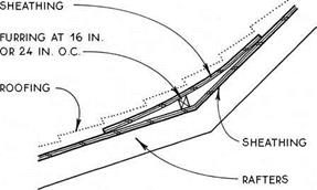
Flashing materials and details must be coordinated with the roofing material to make a durable and waterproof roof. Although design principles are transferable from one type of roofing to another, proportions of materials may vary. For example, the details drawn in this section show a thin-profile roofing material such as asphalt or wood shingles, but flashing for thicker roofing materials such as tile or shake will have different proportions. Some of these special flashings can be found with the details for the particular roofing type.
You may want to use different flashing materials for roofs than for walls, because roofs are constantly exposed to the weather and, in most cases, are replaced much more frequently than walls. (For a discussion of wall flashing materials, see 102.) Moreover, roof flashing itself is not always replaced at the same time as the roof. Chimney or wall flashing may not be easily changed when the building is reroofed, so it should be made of materials like copper or stainless steel, which can last as long as the building. Valley or pitch-change
flashing will be easy to replace at the time of reroofing if the original roof is removed. This flashing may be made of material with a life span equivalent to the roof itself.
The flashing and its fasteners must be compatible with each other and with the roofing material itself. For example, flashing and fasteners for metal roofs must be compatible with the roofing metal to avoid galvanic corrosion. Flashing may be isolated from other materials with 30-lb. felt or bituminous paint.
The basic principle of roof flashing is to have the roofing, the flashing, and other materials overlap one another like shingles. Water running down the surface of the roof should always be directed by the flashing across the surface of the roof. Gravity will then work to direct water down the roof, away from the gaps covered by the flashing. This way, only wind-driven rain can force water through the roofing to the waterproof underlayment (see 177), which acts as a second line of defense. Each detail may have local variations to account for such weather-related factors. All flashing materials, therefore, should be discussed with local sheet-metal contractors or roofers.
 ROOF FLASHING
Introduction


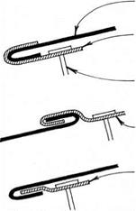
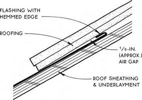
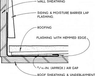
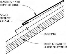
Hemmed edges—One very important detail for roof flashing is the hemmed edge, which folds back on itself about V2 in.
— –
This fold makes the flashing thicker at the edge, which, aside from forming a stronger and neater edge when exposed, helps control the flow of water on roofs, as shown in the drawings on this page. Tucked under roofing, the tumed-up hemmed edge creates an air gap that prevents moisture from migrating between the roofing and flashing by capillary action.
A hemmed edge also works when it is horizontal, as in sidewall flashing (see 171A & B), where the hemmed edge not only resists capillary action but also forms a barrier to water running down the flashing and thus keeps it from running onto the roof sheathing.
Turned down and lapped over roofing, the hemmed edge creates an air gap under the flashing that discourages capillary action. The hemmed edge can also form a seal on smooth surfaces such as skylight glass, which is only made more complete by the presence of water adhering by surface tension to the two surfaces.
Fasteners—Flashing is usually nailed to the structure. Nails are located at the edge of the flashing to avoid punctures in the flashing where it is designed to keep moisture from entering. Care must be taken to select nails that will not cause galvanic corrosion.
Another method of attaching flashing is the cleat, a small metal clip usually made of the same material as the flashing itself. Cleats fasten flashing to the roof without puncturing the flashing and allow for expansion and contraction of flashing metal without dislodging of
used to make concealed
FLASHiNG
 ROOF FLASHING
Hemmed Edges & Fasteners
ROOFiNG

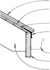
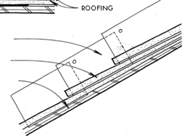
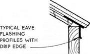
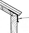 FELT uNDERLAYMENT LAPS OVER METAL EAVE FLASHiNG.
SHEATHiNG
METAL EAVE FLASHiNG WiTH DRIP LAPS FASCiA
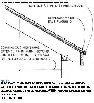
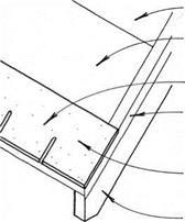


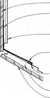

(& gutter).
 LEVEL WALL FLASHING


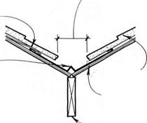
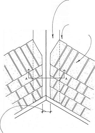
Valleys on roofs, like valleys in the landscape, collect the runoff of all the slopes above them. To handle such a concentration of water, valleys must be carefully flashed. Except when using roofing materials that can bend, such as asphalt shingles or roll roofing, valleys are usually flashed with metal flashing.
Open valley flashing is the most common and may be used with virtually all roofing materials. An open valley allows the runoff water to flow within the confines of the exposed metal flashing rather than over the roofing material itself.
|
NOTE
BITUMINOUS SHEET WATERPROOFING LAPS VALLEY FLASHING IN LOCATIONS WITH SEVERE WEATHER. SEE SECTION A-A AT LOWER RIGHT.
|
|
VALLEY FLASHING EXTENDS FULL LENGTH OF VALLEY.
|
|
■VALLEY BETWEEN ROOFING IS WIDER AT EAVE THAN AT TOP. ESPECIALLY IN AREAS OF EXTREME COLD. TYPICAL VALLEY IS 5 IN. TO 6 IN. WIDE AT TOP AND INCREASED AT Vs IN. PER LINEAR FOOT OF VALLEY.
|
NOTES
FOR VALLEY FLASHING OF ASPHALT SHINGLES.
SEE 183B & C
FOR ROLL ROOFING WITHOUT FLASHING. SEE 181B
Cleats at 2 ft. o. c. fasten valley flashing to the roof without puncturing the flashing and allow for expansion and contraction of flashing metal without dislodging fasteners (see 168). Without cleats, flashing is wider and is nailed at the outer edges.
|
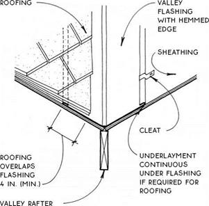
iN LOCATiONS WiTH SEVERE WEATHER, BiTUMiNOUS SHEET WATERPROOFiNG iS LAPPED OVER VALLEY FLASHiNG AT Both Sides FOR LENGTH OF
valley.
|
1-IN. cRIMp IN FLASHING IF ROOF
planes discharge unequal amounts
OF RAINWATER DuE TO
unequal pitches or unequal areas OF watershed.
Section A-A
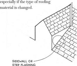
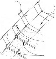
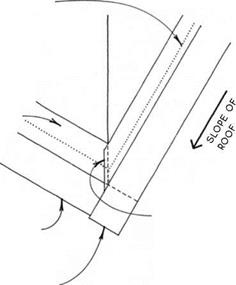
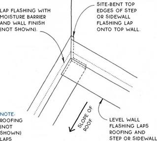
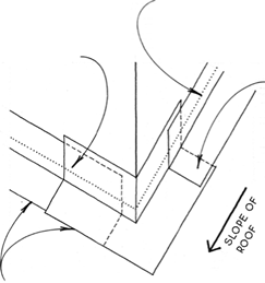
Sidewall flashing is a single-piece flashing installed before the roofing to create a flashing channel against the wall (see 171B). This type of flashing is adequate for most situations and allows easy reroofing.
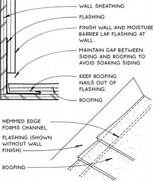 Step flashing is a multiple-piece flashing that is woven in with the courses of roofing material (see 171C). This flashing is best for severe weather conditions. It may present some reroofing difficulties,
|
|
|
|
Posted by admin on 23/ 11/ 15
Framing a valley with trusses is a simple matter of attaching a series of progressively smaller trusses to the top chords of the trusses of the main roof. The main-roof trusses do not have to be oversize since the only extra weight they will cany is the dead weight of the jack trusses themselves. Simple as this system is, many builders still prefer to frame these roof intersections as a farmers valley (see 137) with solid-sawn lumber.
VALLEY FRAMING WITH TRUSSES
Valley Jack Trusses
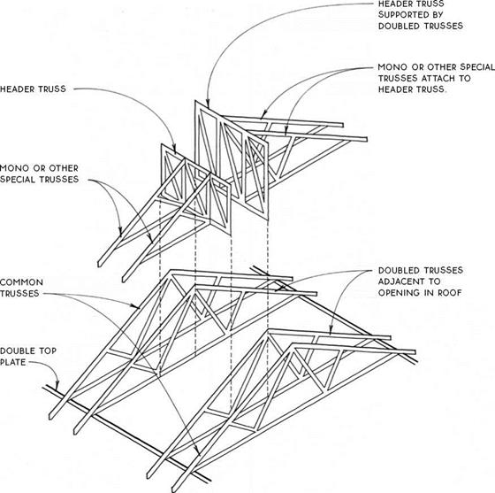
Rectangular openings for skylights or chimneys may be constructed in a truss roof. Small openings less than one truss space wide may be simply framed between trusses as they would be in a rafter-framed roof (see 135-136). Openings up to three truss spaces wide are made by doubling the trusses to either side of
the opening and attaching header and mono or other special trusses to the doubled trusses. Larger openings (more than three truss spaces wide) require specially engineered trusses in place of the doubled trusses. Obviously, it is most efficient if the width and placement of the opening correspond to truss spacing.
|
OPENINGS IN TRUSS ROOF
Headers between Double Trusses
|
|
|
WITH SHEATHiNG
|
|
Posted by admin on 23/ 11/ 15
|
|
|
|
|
|
|
SUPPORT TO RAKE.
|
|
|
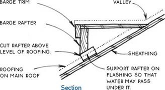
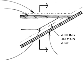
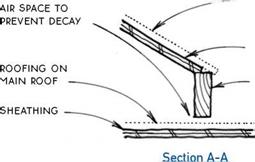
CUT ON FASCiA iS MADE AT PiTCH OF ROOF & ABOVE LEVEL OF ROOFING; FASciA IS SuppORTED ву RAFTERS &
sheathing.
|
|
|
|
|
|
|
|
|
|
 |
|
|
|
|
|
|
|
|
|
|
VERGE RAFTER OR TRiM BOARD CONTiNUOUS TO FASCiA
|
|
|
|
|
furring
continuous
behind
VERGE RAFTER SEE 150A
|
|
|
FURRiNG ALLOWS VERGE RAFTER OR TRiM BOARD TO ACT AS DRiP.
|
|
|
|
|
VERGE RAFTER OR TRiM BOARD
|
|
|
SiDiNG TRiMMED TO cONTiNuOuS FuRRiNG
|
|
|
|
|
fascia shown
MITERED TO VERGE; IT MAY ALSO BE
square-cut & covered WITH TRiM OR GuTTER.
|
|
|
|
|
|

(Q ABBREVIATED RAKE
ABBREVIATED RAKE/EAVE
Corner Framing



 siding
WALL SHEATHING
flashing
NAILING BLOcK
ROOF SHEATHING
ROOFING
2X LEDGER NAILED TO STuDS
2X PuRLiNS
perpendicular TO rafters provide 1V2-IN. AIR space FOR LATERAL AIR MOVEMENT. provide INTAKE & exhaust vents. see 201
 Shed Roof with Continuous Vent Strip

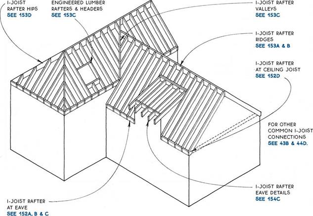
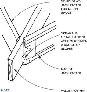
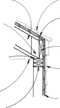
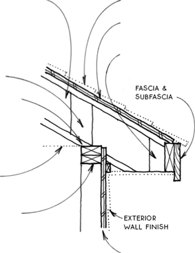
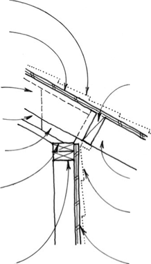
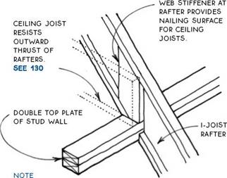
The strength, precision manufacturing, and long lengths that make engineered lumber appropriate for floor framing (see 43A) also indicate its use for roof framing. I-joists used as rafters constitute the bulk of engineered lumber used for roof framing; and they are stiffer, stronger, and lighter than their solid-sawn counterparts, but they also cost more, and their appearance is not generally satisfactory if exposed.
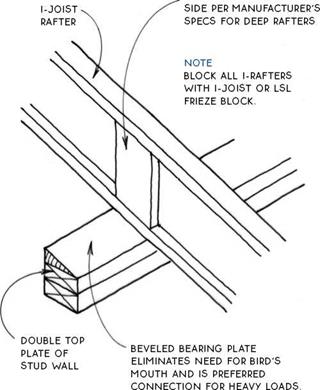
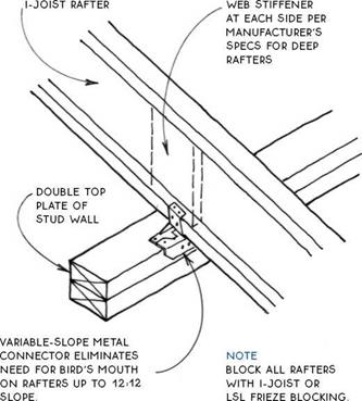
Despite the many advantages, engineered lumber as roof framing has not seen the explosive growth that has been the case with floor framing. Part of the reason is that roof framing with engineered lumber is hardware intensive. Virtually every connection must be made with a metal connector, and most also require the addition of two web stiffeners, one on each side of the I-joist rafters. This adds considerable time and labor cost to the task of roof framing.
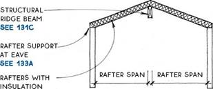
Another difference between framing roofs with solid-sawn or engineered lumber is that engineered lumber almost always requires a structural ridge beam.
This means that roof loads must usually be carried down to the foundation through the core of the building.
The cost/benefit ratio for framing roofs with engineered lumber favors its use only for simple gable or shed roof forms. However, many builders have found ways to combine the advantages of both solid-sawn and engineered lumber on the same building. In these hybrid roofs, engineered lumber is used for the basic forms, and solid-sawn lumber is employed for the smaller-scale parts and the more complicated forms. This mixing of materials is practical for roof construction where differential shrinkage is not usually a significant problem.
The general framing principles that apply to roof framing with solid-sawn lumber also hold true for engineered lumber. To perform as designed, however, engineered lumber roof components must be installed completely in accordance with the individual manufacturer’s instructions. The drawings in this section therefore emphasize roof framing conditions that are specific to engineered lumber.
 l-JQIST RAFTERS
Introduction
|
WEB STIFFENER AT EACH
|
|

I-JOIST RAFTER AT EAVE
With Beveled Bearing Plate
I-JOIST RAFTER AT EAVE
With Metal Connector
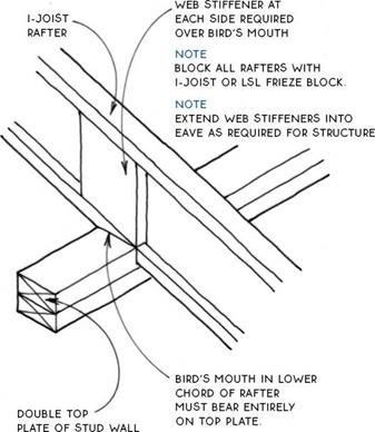

MOST i-JOiST MANUFACTURERS DO NOT SUPPORT THiS DETAiL.
NOTE
BLOCK ALL RAFTERS WiTH i-JOiST OR LSL FRiEZE BLOCK. EXTEND wEB STiFFENERS iNTO EAVE AS REQuIRED FOR
structure.
I-JOIST RAFTER/CEILING JOIST
With Bird’s Mouth
ROOF SHEATHING
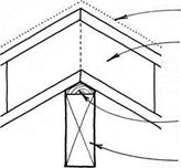 RAFTERS ATTACHED TO EACH OTHER WITH 3A-IN. PLYWOOD GUSSETS ON BOTH SIDES.
DOUBLE-BEVELED WOOD FILLER PLATE
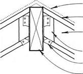
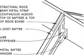 STRUCTURAL RIDGE BEAM
 ROOF SHEATHiNG METAL STRAP i-JOiST RAFTER
WEB STiFFENER METAL RAFTER HANGER STRUCTURAL RiDGE BEAM
дЛ I-JOIST RAFTER/STRUCTURAL RIDGE BEAM


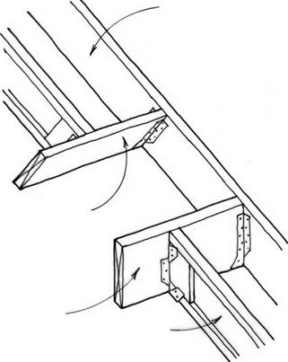 structural rafter


 OF LVL, LSL, OR DOUBLE I-JOISTS ® SIDE OF DORMER. SKYLIGHT. OR OTHER ROOF OPENING
STRUCTURAL RAFTER/HEADER

|
|
|
|
|
|
|
|
|
|
|
WEB STiFFENERS AT BOTH SiDES PER MANUFACTURER’S SPECS –
|
|
|
WEB STIFFENER AT BoTH SiDES pER manufacturer’s specs for deep
RAFTERS
|
|
|
|
|
NAILING block for SuBFASciA
|
|
|
bird’S-mouth cut at lower
FLANGE oF RAFTER MuST HAVE FuLL BEARING oN
plate.
|
|
|
|
|
BiRD’S-MOUTH CUT AT LOWER FLANGE oF RAFTER MuST
have full bearing on plate.
|
|
|
exterior
finish
WALL WITH
trim
|
|
|
|
|
VENTED soffit SEE 202B, c & 203A
|
|
|
|
|
double top plate of stud wall
note
block all rafters with I-joist or LSL frieze BLocK
|
|
|
|
|
double top plate of stud wall
|
|
|
|
 |
 |
|
note
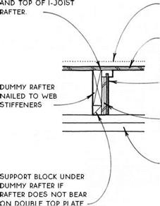
dummy rafter laps I-joist RAFTER 11/2 x distance of overhang.
|
|
|
|
|
align top of dummy rafter
|
|
|
|
|
|
|
|
|
(VENTED)
frieze block SEE 202A
|
|
|
dummy rafter nailed to web
STiFFENERS
i-joist rafter
|
|
|
|
|
|
|
|
|
|
|
double top plate of stud wall
|
|
|
bird’S-mouth cut at lower
FLANGE oF RAFTER MuST HAVE FuLL bearing on plate.
double top plate of stud wall
|
|
|
|
|
|
|
|
 |

 |
Roof trusses, like floor trusses, are a framework of small members (usually 2x4s) that are connected so that they act like a single large member. They are always engineered by the manufacturer.
Engineered roof trusses can span much greater distances than the stick-framed rafter-and-tie system. Long spans (over 40 ft.) are possible with simple trusses so that large open rooms may be designed with roof loads bearing only on the perimeter walls. Interior walls may simply be partition walls and may be repositioned without compromising the roof structure.
A second advantage of roof trusses is the reduction in roof framing labor. Trusses are typically set in place
by the delivery truck and may be positioned and fastened in a fraction of the time it would take to frame with rafters and ties.
One major disadvantage of roof trusses is the difficulty of adapting them to complex roof forms. Roofs with numerous hips, valleys, or dormers are usually less expensive to build if they are framed with rafters.
Another disadvantage of roof trusses is that the webs of the truss occupy space that could be available for storage or as a full-size attic. Furthermore, these webs cannot be cut for any future remodeling purposes.
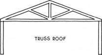
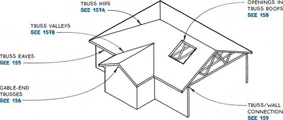
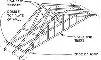
Five common roof truss types are shown in the drawings below.
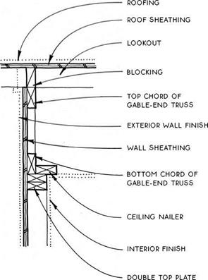
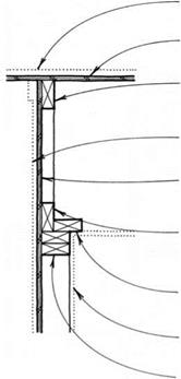 A gable-end truss transfers the load of the roof to the wall on which it bears through 2×4 struts at 24 in. o. c. The standard gable-end truss is the same size as a standard truss. A gable-end truss can be used with a rake overhang of 12 in. or less when the barge rafter is supported by the roof sheathing. It can also be used with flat 2×4 lookouts let into the truss above the struts. A dropped gable-end truss (see 156B) is shorter than a standard truss by the depth of the lookouts.
ROOFiNG ROOF SHEATHiNG
TOP CHORD OR GABLE-END TRUSS
EXTERiOR WALL FiNiSH WALL SHEATHiNG
BOTTOM CHORD OF GABLE-END TRuSS
cEiLiNG NAiLER
iNTERiOR FiNiSH
double top plate
Truss/Gable-End Wall

дЛ STANDARD GABLE-END TRUSS


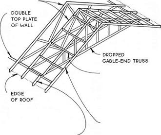 lookouts BEAR ON TOp cHORD OF dropped truss to support rake
OVERHANG.
SEE DETAIL ON RIGHT
Truss/Gable-End Wall
DROPPED GABLE-END TRUSS
There are several ways to frame a hip roof using trusses. None is simple, so many builders elect to frame hips (even on a truss roof) with rafters (see 138).


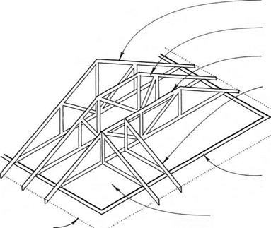

 The most common method of framing a hip with trusses is called the step-down system. A series of progressively shallower trusses with flat tops is used to create the end roof pitch of the hip roof. The last of these trusses is the girder truss, which carries the weight of short jack trusses or rafters that complete the roof.
![]()

![]()


![]()

![]()
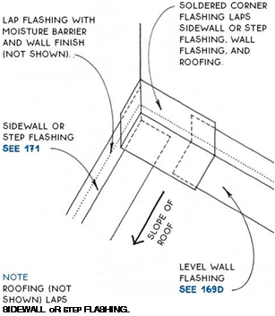
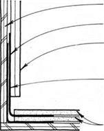
![]() Soldered Flashing for Extreme Weather
Soldered Flashing for Extreme Weather








 NOTE
NOTE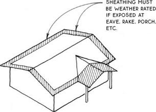


 most manufacturers specify a 1/8-in. space






 FELT uNDERLAYMENT LAPS OVER METAL EAVE FLASHiNG.





 Step flashing is a multiple-piece flashing that is woven in with the courses of roofing material (see 171C). This flashing is best for severe weather conditions. It may present some reroofing difficulties,


 siding


 RAFTERS ATTACHED TO EACH OTHER WITH 3A-IN. PLYWOOD GUSSETS ON BOTH SIDES.
 STRUCTURAL RIDGE BEAM
 ROOF SHEATHiNG METAL STRAP i-JOiST RAFTER

 structural rafter

 OF LVL, LSL, OR DOUBLE I-JOISTS ® SIDE OF DORMER. SKYLIGHT. OR OTHER ROOF OPENING


 A gable-end truss transfers the load of the roof to the wall on which it bears through 2×4 struts at 24 in. o. c. The standard gable-end truss is the same size as a standard truss. A gable-end truss can be used with a rake overhang of 12 in. or less when the barge rafter is supported by the roof sheathing. It can also be used with flat 2×4 lookouts let into the truss above the struts. A dropped gable-end truss (see 156B) is shorter than a standard truss by the depth of the lookouts.


 lookouts BEAR ON TOp cHORD OF dropped truss to support rake


 The most common method of framing a hip with trusses is called the step-down system. A series of progressively shallower trusses with flat tops is used to create the end roof pitch of the hip roof. The last of these trusses is the girder truss, which carries the weight of short jack trusses or rafters that complete the roof.

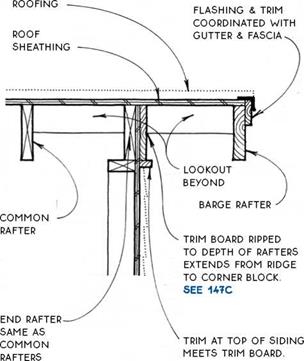
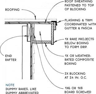


 cOORDiNATE Flashing & TRiM with gutter AND FASciA.
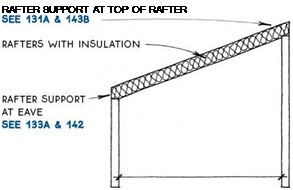

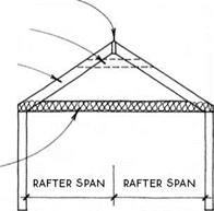
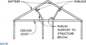
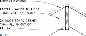
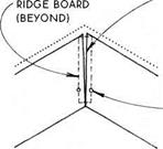
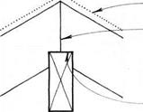
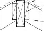


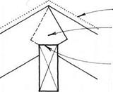

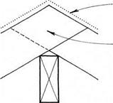


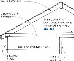
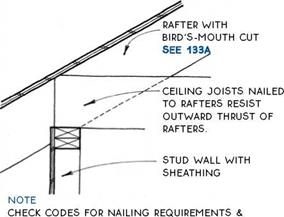
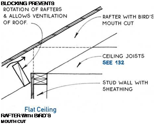

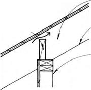

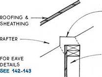
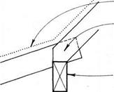
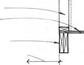
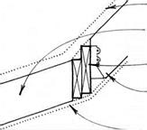 At walls or beams that support them at the eave, rafters are cut at the point of support with a notch called a bird’s mouth.
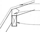

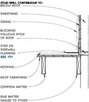
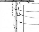
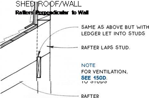
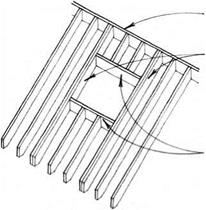
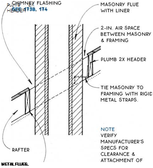
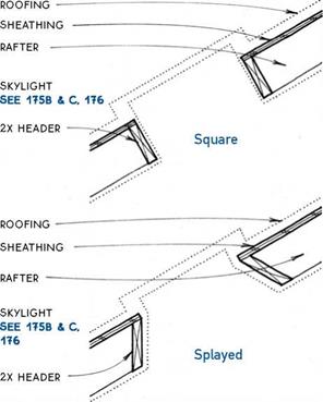
 Framing the elements that project through the roof of a building—skylights, chimneys, and dormers— begins with a rectangular opening in the framing.
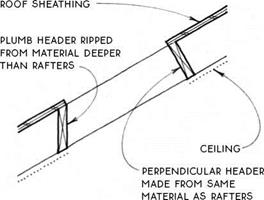
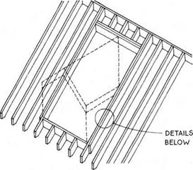
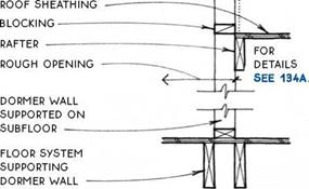

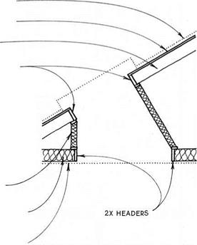


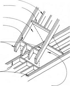
 2X HEADERS

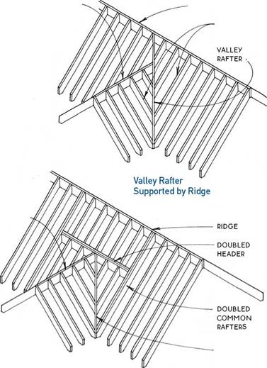


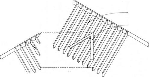
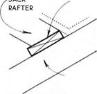

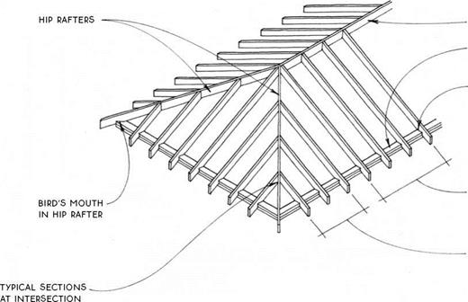

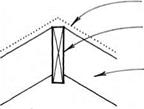

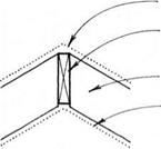


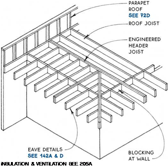

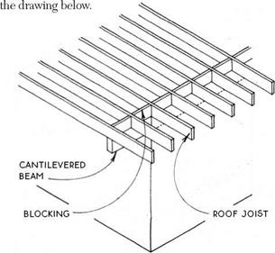
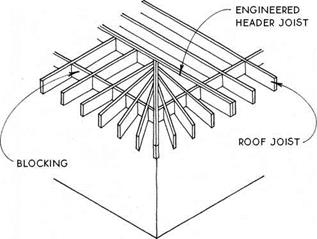
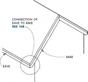

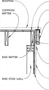
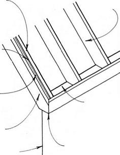
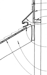
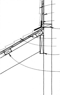
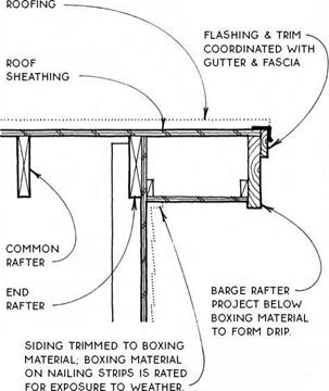
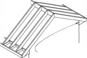
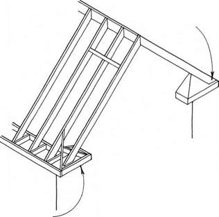
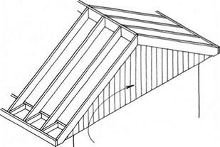
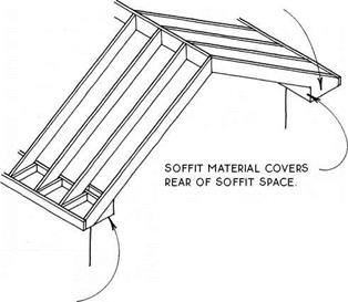
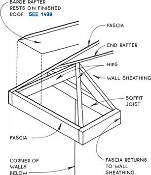
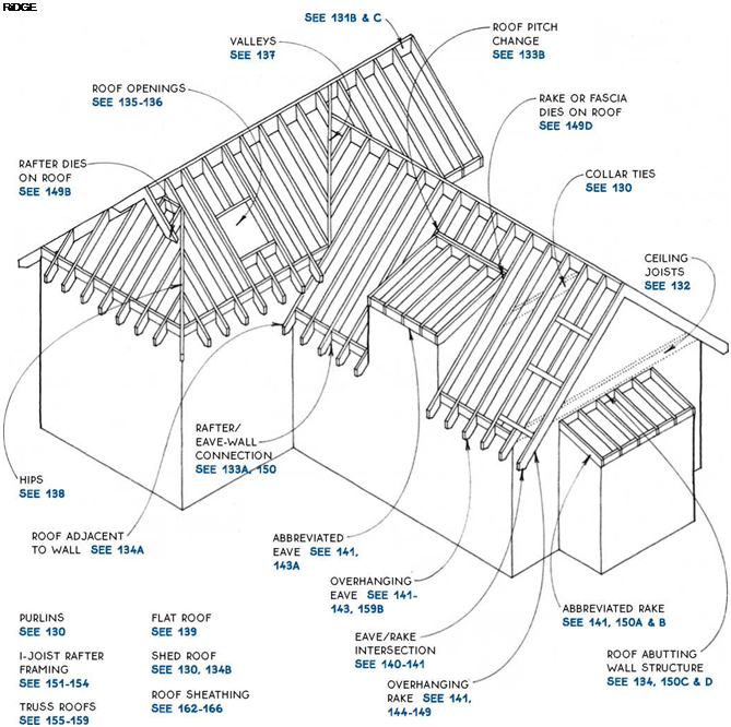
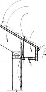
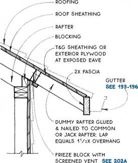
 Functionally, the eave and rake should help protect the building from the elements. The shape of the roof will suggest certain eave and/or rake shapes (see 140B), and certain eave types work best with particular rake types (see 141).


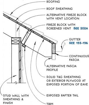
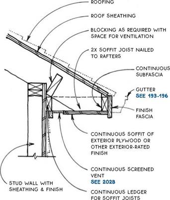
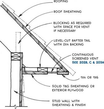
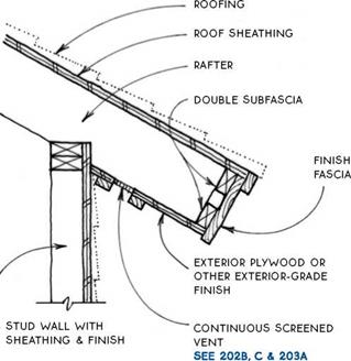

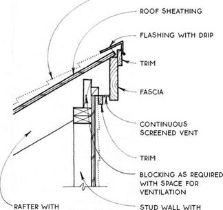
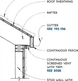



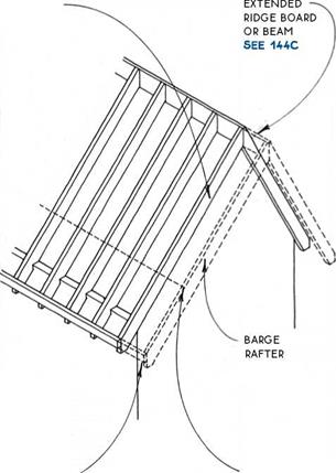
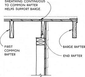


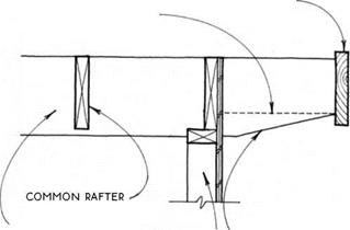


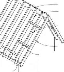


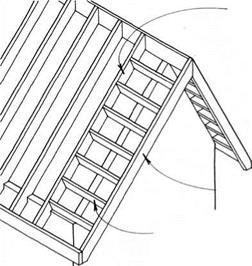

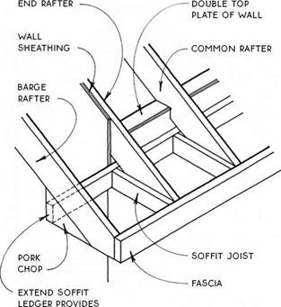
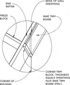
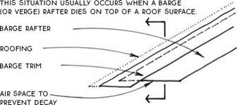
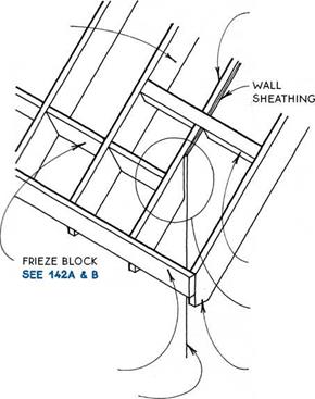
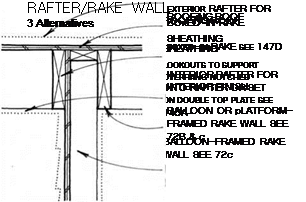
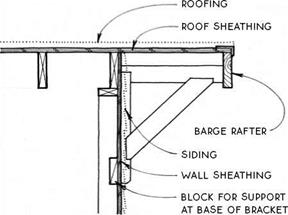
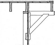
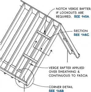
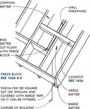
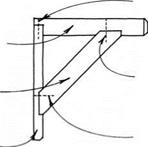 If the ridge, the fascia, and the sheathing together do not provide sufficient support for the barge, lookouts may be added. Lookouts extend from the barge rafter to the first common rafter (or truss) inside the wall. The lookouts are notched through the end rafter at the top of the wall or, alternatively, bear directly on the wall. The size and spacing of lookouts depend on rafter spacing and live loading.
 FOR ALTERNATiVE DETAiL WiTH TRiM BOARD, SEE 147A & B.
