Category Water Engineering in Ancient Civilizations. 5,000 Years of History

Dams of the Iberian peninsula

Spain is one of the oldest Roman provinces – and it is the native province of Trajan and Hadrian. At the end of the Punic wars in 202 BC, Spain is taken by the Carthaginians, who found Cartagena (Carthago Nova). The south becomes rapidly romanized, but the pacification of the northwest is not fully achieved until 19 AD. Toward the end of the 1st century AD the conjunction of the emperor’s protection, along with generalized eco­nomic development in the western provinces and the relatively recent Roman compe­tence in dam technology lead them to build increasing numbers of dams in the area. Today the remains of some 80 structures are known, either dams or weirs, between 1 and 19 m high and of equally variable lengths up to 700 m.[265] Most of these structures serve

Dams of the Iberian peninsula

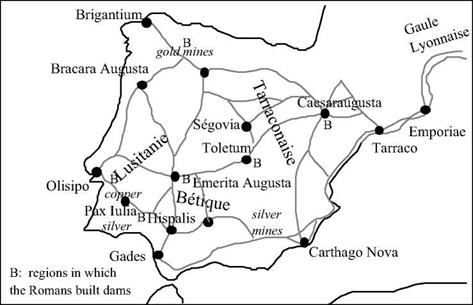
Figure 6.27 Spain and Portugal in the Roman era. The fine lines represent Roman roads.

Dams of the Iberian peninsula

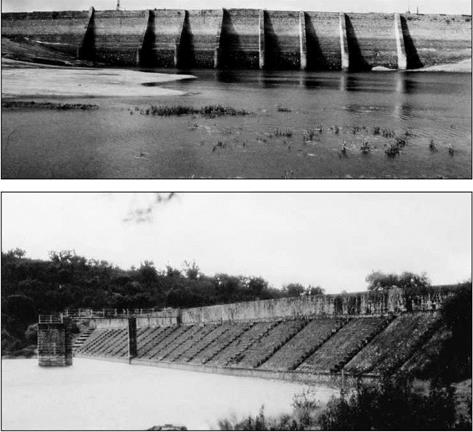
Figure 6.28 The dams of Prosperina (above) and Cornalvo (below), near Merida (Emerita Augusta). These are among the oldest dams still in use, seen from upstream (photos by CEHOPU (CEDEX), Miguel Otero).

the needs of irrigation as well as those of urban and industrial development.

The structures are grouped in rather well defined regions (Figure 6.27). There are nine dams around the northern metropolis of Saragossa (Caesaraugusta), and 15 around Toledo (Toletum), a city situated on the Roman road that links the north of Spain to Lusitania. But the largest number of Roman dams are in the south of the province of Lusitania: twelve around the provincial capital Merida (Emerita Augusta), both for industrial and urban water needs as well as irrigation; and another twenty or so, especial­ly for irrigation, around the cities of Evora (Ebora), Beja (Pax Iulia), and Lisbon (Olisipo), a region of cereal production.

The three largest dams in Spain represent different techniques whose comparison is

Dams of the Iberian peninsula

interesting (Figure 6.29).[266] The oldest of the dams is thought to be that of Alcantarilla, situated at the head of a 50-km long aqueduct that supplies the city of Toledo and cross­es the valley of the Tagus through an inverted siphon. Closely associated with the city of Toledo, the dam’s history may reach back to the 2nd century BC. The structure is 14 m high and 557 m long, and comprises a fairly simple wall supported on its downstream face by buttresses and an earthen embankment to resist the water pressure. The dam failed at an unknown date, for reasons that are not difficult to imagine since debris from the wall seems to have been pushed toward the upstream. It was perhaps after a rapid emptying of the reservoir, or perhaps at a moment when the reservoir was dry and/or rainfall cut channels into the earthen embankment, that the pressure of this embankment

against the dam wall caused it to fail toward the upstream, there being no support on that side.

The two other structures, near Merida (Figure 6.28), clearly are designed to avoid this kind of accident. The dam of Prosperina, 15 m high and 426 m long, is located some 6 km north of Merida. It comprises a masonry wall supported on its downstream side by an earthen embankment like that of the Alcantarilla dam. But the Prosperina dam is also supported on its upstream side by nine thick masonry buttresses. The water intakes are accessible thanks to two shafts in the earthen embankment, right up against the dam wall itself.

The most recent of the three dams is that of Cornalvo, situated 13 km northeast of Merida. The dam is composed of an earthen dike 220 m long, and its maximum height is 20.8 m (19 m to the right of the intake). The upstream face of the dike is compart­mentalized by a series of braces and protected by a revetment on its upper portion. The water intake tower, fitted with intake openings at two levels, is displaced some ten meters upstream of the dam wall, in the reservoir itself, to accommodate the upstream embankment slope. This arrangement is typically seen in modern dams.

It is difficult to assign a date to the construction of these dams. It has been proposed that Prosperina dates to the period of the reign of Trajan, around 100 or 110 AD, or 75 years after the founding of Merida. Cornalvo is thought to date from the period of Hadrian, around 120 or 130 AD. The Prosperina and Cornalvo dams are still in service today, nearly in their original state, thanks to their particularly wise design and good maintenance.

Romans and dam technology

In about 60 AD the Emperor Nero built his villa at Subiaco, on the river Anio upstream of Tivoli (Figure 6.8). He formed lakes for his personal pleasure by damming the river. The largest of the structures he built for this purpose is across a natural gorge and at 40 m, is the highest dam of all the Roman Empire. Rectilinear, 80 m long at its crest and 13.5m thick, it is what one would call today a gravity dam, relying on friction at its base to resist the force of water in the reservoir behind it. This dam remained standing until 1304, when the monks of a neighboring monastery dismantled it to recover the stones for other use.[263] Forty years after Nero, Frontinus built the new intake for the Anio Novus aqueduct on one of these lakes to improve the quality of its water, as we have seen earlier.

Nero’s dam at Subiaco is not only the highest, but also one of the first dams con­structed by the Romans, and the only one in Italy. Since dams were not essential to the development of Italy, dam technology is not a traditional Roman discipline (Vitruvius says nothing of dams in his treatise On Architecture). We have seen in the first part of this book that numerous dams were built in the Orient from the IVth millennium BC. It is undoubtedly through their domination of the Orient (Syria-Palestine, Egypt) and through their military expeditions (Yemen) that the Romans acquired this technology and then further developed it, especially from the 1st century AD.

Like those of the Orient, Roman dams are almost always of the gravity type, the one at Subiaco being a good example. These dams most often are built of simple rectilinear walls of masonry or concrete, supported by earth fill or buttresses, as we will see further on. However the Romans also invented the arch dam, a structure whose shape enables it to transmit the pressure force of impounded water to the lateral valley walls, just as the arch of a bridge transfers the load to its supporting piers.

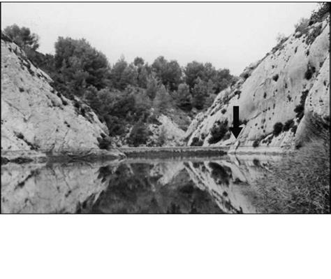
In the valley of the Baume, several kilometers south of Saint-Remy-de-Provence in France, are the remains of a structure that is now buried under a dam built in 1891. A provincial scholar named Esprit Calvet fortunately discovered these remains in 1765 before they were buried. The principal vestiges of the dam are the keyways in the val­ley walls where the dam abutments were anchored. The shape and alignment of the key – ways, which extend somewhat above the level of the modern dam, reflect and reveal the curvature of the structure (Figure 6.26).

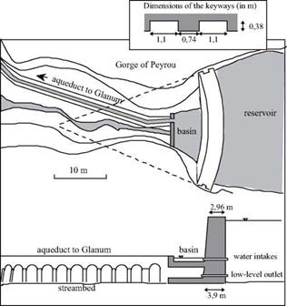
A recent study led to reconstitution of the dimensions and function of this Roman dam.[264] It is likely during the time of Augustus that the Romans built the dam in the nar­row gorge of the Peyrou to supply an aqueduct leading to the nearby Roman city of Glanum. This structure, the first known arch dam, is nearly 15 m high, 23.8 m wide at its crest, and has a radius of curvature of about 30 m. The dam is keyed into the nearly vertical rock walls of the valley at its two ends. It apparently is built of either two faces of quarried rock blocks with an impermeable fill, or perhaps a solid mass of mortared blocks with a watertight joint.

Romans and dam technologyFigure 6.25 The dam in the Baume valley, near Sant-Remy-de – Provence: the oldest known arch dam (from the reconstitution of Agusta-Boularot and Paillet, 1997). The water transported by the aqueduct is destined to supply a massive fountain at Glanum, perhaps a watering station for migrating herds. The aqueduct is 500 m long, with a slope of 3.2 m/km. The canal is 0.59 m wide, and 0.89 m deep.

Romans and dam technologyFigure 6.26 In the Baume valley, site of the Gorge of Peyrou, seen from the reservoir. The arrow shows the location of the keyway of the Roman dam, at the right extremity of the present-day dam (photo by the author).

To the south of Evora in Portugal there is another small arch dam: Monte Novo. It is less than 6 m high, but is probably of Roman heritage.60 The only other known exam­ple of an arch dam revealing Roman techniques is the one built at Dara (Anatolia) in the Byzantine period (Chapter 7).

The dams built for Nero on the Anio were expressly for the personal pleasure of an emperor. On the other hand, the dams that we describe now respond to economic needs; the provinces had to produce enough food to supply the Empire. In Spain, in North Africa, and as always in the Orient, irrigation was essential to the development of agri­culture.

Economic development of the provinces: dams for irrigation and industry

The abundance of water and water infrastructure in the city of Rome not only provides for essential needs, but also serves as a cultural background for the urban life and pleas­ures of Rome’s citizens. Water plays an equally important role in the economic devel­opment of the Roman provinces. We have already described the development of the water wheel as it appeared in all of the Empire. But water management and exploitation went much further than this. Water had to be removed from the deepest galleries of mines, and massive quantities of water were needed to obtain lead, silver, and gold from their ores; the remnants of such ore-washing installations have been found in many of the provinces. In addition, the textile industry relied upon a steady supply of water. There is also of course agriculture, for which irrigation is required to support plentiful yields in southern and eastern regions. It is in these provinces, where water is less abun­dant and often scarce, that there is the most plentiful archaeological evidence of water acquisition and use. The most spectacular evidence is that of the Roman dams construct­ed in Spain, North Africa, and the Orient. Before describing these projects, as well as projects other than dams, let us first introduce Roman dam-construction technology.

Development of the water mill in the Roman Empire

About fifty years after Vitruvius, under the reign of Vespasian and Titus, Pliny the Elder[255] wrote in his book, The Natural History:

“All the grains are not easily broken. [….] Throughout the greater part of Italy, however, they employ a pestle that is only rough at the end, and wheels turned by water, by means of which the corn is gradually ground.”[256]

The Roman development of the water mill has been consistently underestimated; but new archaeological findings are becoming more and more numerous.[257] One can find remains of simple mills on small rivers near Hadrian’s Wall at the Scottish border.[258] In eastern Tunisia, at Chemtou (the Roman Simitthus) the remains of an installation com­prising three horizontal wheels set side by side have been found near a dam constructed by Trajan on the river Medjerda.[259] And in North Africa, there are still other horizontal – wheel mills. Vertical-wheel mills are found in Gaul from the 1st or 2nd centuries; in the villas ofVar in the 2nd century; on the Janiculum Hill at Rome from the 3rd century; and at the agora of Athens in the 5th century. There is a depiction of a noria on a mosaic dat­ing from 469 AD at Apamea-on-Orontes; this date comes after the fall of the Roman Empire in the west, but the representation suggests that the use of the noria had largely spread to the east during the Roman period. And then, there is the flour mill of Barbegal.

Let’s now describe this installation,[260] the one we used to begin our discussion of

Development of the water mill in the Roman Empire

Figure 6.22 Roman flour mill at Barbegal: view from the summit of the rock outcrop where the aqueduct arrives; to the left and the right, in the form of a V, one can see the two walls that carried the two divergent lateral canals. These canals delivered water to the two “mill” canals that, in turn, cascaded down the slope and supplied the two banks of water wheels (photo by the author).

Подпись: Figure 6.23 The remains of the Roman hydraulic flour mill, comprising two series of eight paddle wheels. View from below, remains of the right-hand canal. The arrows indicate the flow path (photo by the author).
Development of the water mill in the Roman Empire

Roman mills. We have seen that the aqueduct that is dedicated to the supply of the flour mill lies parallel, in its final stretch, to the aqueduct that supplies the city of Arles. Both aqueducts come out of a junction basin which is supplied, in its turn, by two canals deliv­ering water from different remote sources.

At the mill, another distribution basin[261] conveys water into two parallel headrace canals that descend from the hill with a discharge that modern studies have estimated at about 0.15 m3/sec. Along each of these canals, eight vertical wheels, each about 2 m in diameter, are aligned from the top to the bottom of the slope. Each wheel has a sill or weir immediately downstream of it, controlling flow into a small drop that feeds water onto the wheel below it. Adjacent to each wheel, near its center, is a chamber enclosing the reduction gears, with grinding wheels likely set on a platform above each of these chambers.

One of the astonishingly modern aspects of this installation is its engineered, non-nat­ural water supply, using one of the two branches that earlier had come together to supply Arles. The mill was built at a very convenient location, benefiting from a steep slope and yet providing ready access from the plain below, obviating the need for the installation to accommodate the vagaries of a natural river. The discharge is regular, with no risk of erosion. This installation probably dates from the beginning of the 2nd century AD.[262]

Development of the water mill in the Roman Empire

Figure 6.24 Reconstitution of the plan of the flour mill of Barbegal (after Sellin, 1979). The light lines indicate assumed structures.

Water lifts, paddlewheels, and water mills in the world of Vitruvius

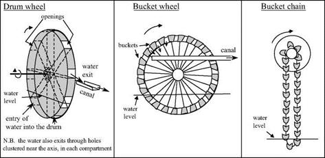
Vitruvius provides the oldest known description of a water lift powered by hydraulic force, or noria, and of a water mill. This description comes immediately after that of manual water lifts (drum wheel, bucket wheel: see Figure 6.20):

“Wheels on rivers are constructed upon the same principles as those just described (manual lift wheels). Round their circumference are fixed paddles (pinnae), which, when acted upon by the force of the current, drive the wheel round, receive the water in the buckets, and carry it to the top with the aid of treading; thus by the mere impulse of the stream supplying what is required.

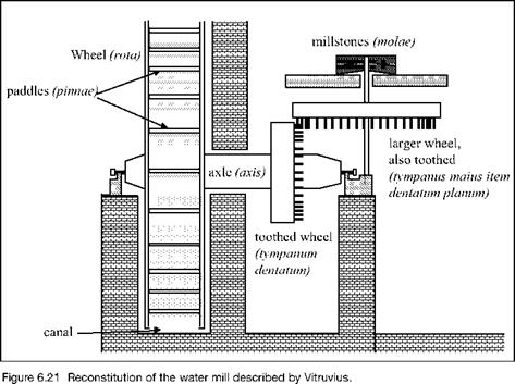
“Water mills (hydraletae) are turned on the same principle, and are in all respects similar, except that at one end of the axis they are provided with a drum-wheel, toothed and framed fast to the said axis; this being placed vertically on the edge turns round with the wheel. Corresponding with the drum-wheel a larger horizontal toothed wheel is placed, working on an axis whose upper head is in the form of a dovetail, and is inserted into the mill-stone. Thus the teeth of the drum-wheel which is made fast to the axis acting on the teeth of the horizon­tal wheel, produce the revolution of the mill-stones, and in the engine a suspended hopper supplying them with grain, in the same revolution the flour is produced.”[250]

Figure 6.21 is an attempt to reconstitute the devices described by Vitruvius. We

Water lifts, paddlewheels, and water mills in the world of Vitruvius

Figure 6.20 The manual water lifts described by Vitruvius, the possible origins of the noria and water mill. The lift height increases from left to right.

recall that he was a contemporary of Augustus (about 25 BC), and therefore came after the reign of Mithridate, though by only a few decades. He doesn’t enlighten us on the details of the innovation much better than did the Greek sources that we cited in Chapter 5. These details and their origins therefore remain somewhat obscure. However, two clues enable us to form at least a rough idea of how the devices operated.

Water lifts, paddlewheels, and water mills in the world of Vitruvius

The first clue is Vitruvius’ outline, the order in which he describes the different machines. He puts his description of the water mill in between those of the water lifts – as in Figure 6.20. He first describes the drumwheel, then the bucket wheel, and finally the bucket chain. All three machines are powered by human muscular force, and raise water to increasing heights in the order they are listed. It is after these descriptions that Vitruvius describes the paddle wheel powered by the force of the current and equipped with buckets to lift the water, and then finally the mill that turns a grinding stone using hydraulic force.

Vitruvius’ work then comes back to lifting machines, presenting two inventions of the 3rd century BC that we have already seen: the Archimedes screw or limagon, and the pump of Ctesibios.[251] Certain authors[252] believe it is possible that the order in which these machines are described, an order whose logic is not at all obvious, must correspond to a technical genealogy of these wheels. The manual bucket wheel could have been per­fected through the addition of paddles, so that it could be powered by the force of the current. In this case the paddle wheel could have been used to lift water (this is the noria, an invention destined to have a glorious future in the Orient), before it was real­ized that the rotation of the wheel could, through appropriate gearing, be used to turn a millstone. Other authors[253] propose that the vertical-axis mill (having a horizontal mill­stone) was invented first, since it does not require reduction gearing to turn the stone. Moreover, this mill appears in China at about the same time, as we see further on in Chapter 8.

A second clue as to the first use of the paddle wheel can be found a bit further on in the same book X of Vitruvius. There, he describes procedures “passed down to us from our ancestors” (which ones?) to measure travel distances over land or water; these would be “hodometers”. After describing the adaptation of the idea to chariots, Vitruvius then describes an analogous procedure for measuring the distance traversed through the water by boats. It is the paddle wheel that comprises the essential part of this instrument:

“In navigation, with very little change in the machinery (i. e. the hodometer for wheeled char­iots), the same thing may be done. An axis is fixed across the vessel, whose ends project beyond the sides, to which are attached wheels four feet in diameter, with paddles (pinnas) to them touching the water. [….]

“Thus, when the vessel is on its way, whether impelled by oars or by the wind, the paddles of the wheels, driving back the water which comes against them with violence, cause the wheels to revolve, whereby the axle is also turned round, and consequently with it the drum-wheel, whose tooth, in every revolution, acts on the tooth in the second wheel, and produces moder­ate revolutions thereof.”[254]

We know that on modern ships a common instrument for measuring the speed is a small paddle wheel. However the procedure described by Vitruvius appears curious to say the least, and it seems doubtful that its use was widespread.

Paddle wheels and water mills in the Roman world, the beginnings of industrial use of water

In the provincial countryside some ten kilometers from Arles in the direction of Saint-Remy-de-Provence, a hiker can come upon the remains of Roman aqueducts on arches. These remains are even indicated by a sign. Looking at the remains closely, the tourist can easily see that there are in fact two parallel aqueducts, side by side. If the hiker follows the path alongside these aqueducts, he or she comes upon a deep notch cut in a rocky outcrop. The canal of the left aqueduct passes through this notch (Figure 6.19).

After passing through this notch, our hiker then comes out at the top of an escarp­ment, 20 meters high along a length of 60 meters, beyond and below which is a broad plain with no visible trace of the aqueduct. On the slope one can recognize the ruins of walls and structures in the form of stairways (Figure 6.22). These ruins were identified in 1935 by Fernand Benoit as those of a Roman hydraulic flour mill, the mill of Barbegal, the very first of this kind known to us.

Paddle wheels and water mills in the Roman world, the beginnings of industrial use of water

Figure 6.19 Barbegal: the remains of the canal of the left-hand aqueduct, and the notch in the rocky outcrop that marks its end (the right-hand aqueduct, though it cannot be seen in this photo, turns sharply before the rocky outcrop and continues its route toward Arles) (photo by the author).

In Chapter 5 we mentioned the appearance of the water mill in Asia. This was only weakly suggested by an allusion of Strabo to the mill in the palace of Mithridate, king of Pontus, conquered by the Romans in the middle of the 1st century BC. The appear­ance of this device marked a major step in the history of technology, but passed almost unnoticed. With the Romans, the first written evidence of a mill is found in book X of Vitruvius’ work. Let us examine how Vitruvius describes the new technology to get a clearer idea of how it appeared.

Other aqueducts in the Roman Empire

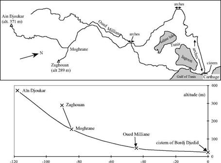
The panorama of Gallo-Roman aqueducts that we have just described represents the diversity of situations and solutions adopted throughout the Roman Empire. Table 6.1 gives an incomplete list of the numerous Roman aqueducts that have been discovered and studied. It would be impossible to describe all of them. To the best of our knowl­edge, the longest one is at Apamea-on-Orontes in Syria, built in 116 or 117 AD as part of the broad reconstruction after the earthquake of 115 AD.[246] But another aqueduct also merits our attention. It is the aqueduct of Carthage, one of the marvels of Roman archi­tecture in Africa, and among the longest of all the Roman aqueducts in the western world (Figure 6.18).[247]

Carthage is destroyed by the Romans at the end of the Punic wars, then rebuilt in 29 BC by Augustus for the purpose of granting property to legionnaires at the end of their service, and then later becomes a capital of the province of Africa. With completion of the great thermal baths of Antonio, it becomes necessary in 162 AD to build an aqueduct to supply numerous public fountains, and also to build cisterns to store rainwater. But the usable water sources are some distance away, in Djebel Zaghouan. The closest source is 56 km away as the crow flies, with obstacles in the way including a lagoon to the east of Tunis, and a saline lake somewhat further. At the wide valley of the wadi Milliane there is a crossing of 4.5 km on arches that are some 20 m high in places, and a two-level bridge 126 m long and 34 m high.[248] In this plain of Carthage there are 17 km of crossings on high arches in all. Later on, very likely under the Severus emperors, the aqueduct is lengthened to 132 km, to capture the even more distant springs of Ain Djoukar.

Other aqueducts in the Roman Empire

Distance from the cistern at Carthage (km)

Figure 6.18 The aqueduct of Carthage: map of the alignment and schematic longitudinal profile (after Rakob, 1979). Only the points indicated (x) are exact, the remainder of the profile is deduced from simple interpolation. The maximum capacity is estimated at 25,000 m3/day.

Like the Pont du Gard in Europe, the aqueduct of Carthage and its appurtenances attract the admiration of African observers:

“This distance, from the source (Ain Djoukar) to the cisterns (the 24 cisterns of Carthage) was covered thanks to an infinite number of aqueducts, in which water flowed at a constant level. These aqueducts were composed of stone arches. When these were on the ground, they were low and when they were in the depressions or valleys, they were extremely high. This was one of the most remarkable things to be seen on the surface of the earth.” [249]

The upstream portion of the aqueduct is still used today by the Tunisian water service.

The Nimes Aqueduct and the Pont du Gard[242]

Подпись: Figure 6.14 The Roman aqueduct of Nimes (after Fabre, Fiches, Leveau, Paillet, 1992).
The Nimes Aqueduct and the Pont du Gard[242]

The Roman Nemausus (Nimes) is much older than Lyon, founded in the 6th centu­ry BC, even before the conquest of Gaul by the Romans. Nimes was the capital of the Arecomic Volques, a Gallic people often allied with the Romans. Nimes is naturally well supplied with water, from wells and especially from the Fontaine spring, abundant and perennial. Under Augustus the spring was the subject of major construction, including a masonry canal and basin at its outlet. The need for an aqueduct only came later under the pressure of urban development (20,000 inhabitants in the Gallo-Roman Nemausus), with the objective of supplying water to the highest areas of the city above the level of the Fontaine (at an elevation of 51.1 m). Under Claudius, in the middle of the 1st cen­tury AD,[243] the Eure fountain spring is tapped near Uzes at an altitude of 72 m.[244]

Подпись: Figure 6.15 The Pont du Gard, supporting the aqueduct of NTmes across the Gardon (photo by the author).
The Nimes Aqueduct and the Pont du Gard[242]

Although it is only some 20 km from the source to Nimes as the crow flies, the aqueduct had to wind around the vast scrubland plateau of Nimes, whose elevation is above 100 m (see Figure 6.14). There are numerous obstacles to be crossed on this plateau. These obstacles include ravines that are dry in summer but subject to violent floods, such as the Bornegre ravine with its three-arch bridge; passes, with the two-level arched bridge of Font-Menestiere; and notably the sunken valley of the Gardon, across which the highest bridge-aqueduct of the Roman Empire is built, the Pont du Gard (Figure 6.15). The bridge is about 360 m long, and carries the canal of the aqueduct at an altitude of 65 m, some 48.4 m above the bed of the river. Just upstream of the bridge the canal has a basin provided with a gate and a discharge canal enabling diversion of the discharge of the aqueduct (or its excess) into the Gardon, if necessary. Downstream of the bridge, the canal traverses the rough terrain along the edge of the limestone plateau by means of multiple switchbacks, crossing ravines on small bridges. The canal passes through three tunnels of about 400 m in length, further downstream near Sernhac, then again near 39

The Nimes Aqueduct and the Pont du Gard[242]Nimes. The terminal point of the aqueduct is the water tower in the city (castellum), at an elevation of 58.95 m.

All of these bridges are designed to handle the strong floods typical of the Mediterranean climatic regime. The bases of the bridge piers are protected by shaped prows on the upstream face. The bridges all leave a very large opening for flood pas­sage; the widths of the openings of the arches of the Pont du Gard are 24.5 m and 19 m.

The castellum of Nimes (Figure 6.17) is one of the rare Roman water towers still conserved in more or less its original state. The aqueduct dumps water into the tower’s

The Nimes Aqueduct and the Pont du Gard[242]

Figure 6.16 Longitudinal profile of the Nimes aqueduct, from the data of Fiches (1991).

Figure 6.17 The castellum of Nimes: this distribution basin is the terminal point of the Nimes aqueduct. It is visible in the city, on rue de la Lampeze (photo by the author).

circular basin of 5.5 m inside diameter and depth 1.4 m. Issuing from the basin are ten circular distribution pipelines of 0.4 m diameter. Valves enable the isolation of one cir­cuit or another, and drains in the bottom make it possible to empty the basin.

The aqueduct has several slope changes;[245] upstream of the Pont du Gard it is only 38 cm/km on the average, which is relatively small compared to other aqueducts. But downstream of the bridge, the slope is only 8 cm/km along a particularly sinuous seg­ment of more than 10 kilometers length. The theoretical maximum discharge for this slope can be estimated at around 40,000 m3/day. Even though this aqueduct may not attract the same admiration as the Pont du Gard, it is all the more impressive for its incredibly small slope, and the precision of surveying and construction that this implies.

These slope changes have hydraulic consequences that were not well understood or mastered by the Roman engineers. In a canal of constant width, the depth of water is larger when the slope is small; yet the Nimes aqueduct was initially constructed for an essentially constant depth. Early on, it became necessary to raise the canal walls in sev­eral locations (of flatter slope) to avoid overflow.

Another problem is the fact that the water from the Eure fountain is very calcareous. Over the years, the useful cross-section of the aqueduct’s canal becomes considerably reduced by deposits, effectively reducing the discharge to a value that was probably only about 20,000 m3/day. The canal had to be scoured out on several occasions.

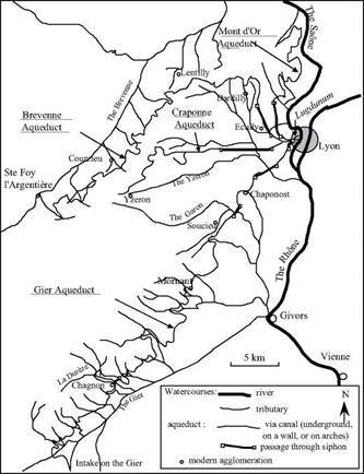
The aqueducts of Lyon

Lucius Munatius Plancus founds Lugdunum (Lyons) in 43 BC on the Fourviere hill, 130 m above the waters of the Saone and Rhone rivers. Thirty years later, Augustus makes Lyon the capital of Gaul. It is often the case that such cities are initially established on high ground for strategic reasons, and consequently not well supplied with water. Then the cities rise in importance to become regional capitals, necessitating significant efforts to provide adequate water supply. This was the case of Pergamon as we described in Chapter 5.

At Lugdunum, it was necessary to cross a valley some hundred meters deep to reach the Fourviere hill, only its western facade being accessible. As at Pergamon (but sever­al centuries later), large inverted siphons, the largest in all the Roman world, are used to bring water across the deep valley.

The aqueducts of Lyon

Figure 6.11 The four Roman aqueducts of Lyons.

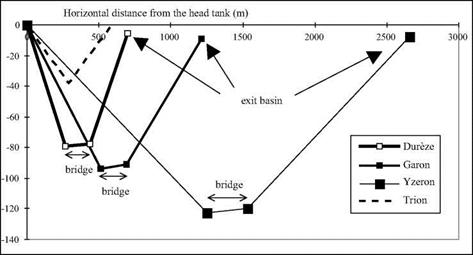
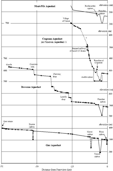
Figure 6.12 Longitudinal profiles of the four Roman aqueducts of Lyon (Burdy, 1979, 1986); the dark squares represent known points.
The aqueducts of Lyon

Four large aqueducts supply water to the Roman Lugdunum. They have been the sub­ject of numerous archaeological investigations[235]. Their remains are still visible, but unfortunately are degrading over time; however some additional remains are surfacing during modern construction projects. The construction chronology of these aqueducts is not known with certainty, indeed it is based on hypotheses. One of these hypotheses is that the Mont-d’Or aqueduct, issuing from the mountain of the same name, was the first to be constructed, about 10 BC by Agrippa, the son-in-law and close collaborator of Augustus. (Agrippa was a great aqueduct builder – Rome owes the Julia and the Virgo to him). The Mont-d’Or aqueduct is 28 km long, with two siphons. It is the smallest of the aqueducts in terms of dimensions and discharge, and only a few traces of it remain today.

It is very likely that the Craponne aqueduct (sometimes called the aqueduct of the Yzeron) was built next from catchments developed upstream of the village of Yzeron at 700 m altitude, perhaps under Augustus.[236] This canal is noteworthy for its slope of nearly 17 m per kilometer on the average, i. e. five times steeper than that of the Mont – d’Or aqueduct. Vortex drop shafts constitute what amounts to “hydraulic stairways”. Though the Craponne is of similar length and dimensions to the Mont-d’Or, it is distinc-

The aqueducts of Lyon

Figure 6.12b. Comparison of profiles along the four siphons of the Gier aqueduct. The Dureze siphon has the most pronounced slope, which can be explained by its later construction (hypothetical) by the Chagnon loop. Note the slightly rising profile (1 % ca.) of the siphon bridges, which allows evacuation of air pockets downstream – discovered by the work of Burdy (1996).

tive in having a double siphon.

To understand this double siphon, it is useful to reconsider, yet again, the great siphon of the Pergamon aqueduct, whose longitudinal profile shows a high point (Figure 5.10) with a risk of air accumulation. The Craponne includes a free-surface reservoir that stands 15 m above the ground on an intermediate plateau (the Tourillon de Craponne). This reservoir enables the aqueduct to cross two valleys over a total length of 5.5 km, avoiding the problems of a high point. It serves as both an exit basin, or out­let box, for the upstream portion of the siphon and a head tank for the longer downstream portion, which dips through nearly 70 m of elevation.

The Brevenne aqueduct is a very large installation 66 km in length, whose construc­tion could date from the Emperor Claudius in the middle of the 1st century AD. It issues from the Lyon mountains and is buried for the first forty kilometers. Then it follows the valley of the Brevenne and, after some twelve kilometers, has an increased cross section to accommodate intermediate catchments. This aqueduct also has particular distinctive features. It crosses significant elevation changes in short distances at four locations. At Courzieu, it drops nearly 44 m in less than 200 m; then at Chevinay, there is a drop of 87 m in 300 m, and again three other drops of from 30 m to 40 m each. Downstream of the drop of Courzieu, there is a small basin some 45 cm deep and 80 cm long, likely intended to provide energy dissipation as well as to trap transported sand and gravel. Moreover, there is a contraction of the canal at the location of the last drop, at Lentilly; the normal width of 75 cm decreases to 44 cm. It can be shown that in the reaches of steep slope, the flow is supercritical.[237] As for the other aqueducts, the Brevenne terminates at a siphon. It probably merges with the Craponne aqueduct at its entry into Lugdunum.[238]

The fourth aqueduct, Gier, issues from an intake on the river of the same name and is the longest at 74.5 km. The Gier is the aqueduct that was most carefully constructed, and its art features, bridges, and arcades reflect the majesty of the all-powerful Empire at its peak. Ample remains of the Gier are still visible today, in particular its bridges and parts that were supported on arcades. Traditionally the Gier is attributed to the time of Hadrian (beginning of the 2nd century AD), but recent indices (in particular a fountain bearing the name of Claudius) lead us to date the works from the reign of this emperor. The Gier also has two curious features. In parallel with the first siphon, that crosses the Dureze over a length of 900 m, there is a large derivation into a canal of small slope (only 0.5 m/km). This derivation canal goes around the village of Chagnon (the “loop of Chagnon”) for a distance of 11.5 km (making the total length of the aqueduct some 86 km). The purpose of this derivation is not obvious. Along the path of this loop, there is an inscription on a stone noting the rules for riparian use of the aqueducts:

“By order of the Emperor Cesar Trajan Hadrian Augustus, no one has the right to work, har­vest, or plant in this space that is intended to provide protection for the aqueduct.”[239]

The aqueducts of Lyon

There has been much discussion as to the relative age of the loop and the siphon. If indeed the aqueduct dates from the reign of Claudius, the inscription shows that the der­ivation canal, in service under Hadrian, postdates the siphon. This may be because the

siphon had maintenance or operational problems caused by the steep slopes in the val­ley of the Dureze (see Figure 6.12b).

Upstream of the first siphon there is also evidence of an abandoned earlier alignment along 40 km, dug deeply into the rock parallel to the aqueduct, but 8 to 10 m higher. Could this reflect a surveying error?

Further downstream, the Gier aqueduct passes under the village of Mornant in a one – kilometer curved tunnel more than 20 m underground. It has four siphons in all (table 6.4). The third of these siphons crosses the Yzeron valley. 2,660 m long and dropping 122 m, it is the largest siphon of all those in the Lyon complex.

There are eight siphons in all in the four aqueducts of Lyon. Following the specifi­cations in the manual of Vitruvius, each siphon has an exit basin, a head tank, and at the bottom of the valley, a bridge-siphon. The Tourillon de Craponne comprises what

Table 6.4 Approximate characteristics of the eight siphons of the Lyon aqueducts (the siphons of the Gier aqueduct are the best known; see Burdy, 1996).

Aqueduct

Mont-d’Or

Craponne (double siphon)

Brevenne

Gier

Valley

Rochecardon Planches

Corvelet Charbonnieres

Planches

Dureze

Garon

Yzeron

Trion

crossed

Length

500 m?

3,500 m

2,200 m 3,600 m

3,500 m

700 m

1,210 m

2,660 m

575 m

Drop

25 m?

66 m?

33 m? 91 m

91 m

78.5 m

93 m

122.3 m

38 m?

Head loss[240]

4 m?

11 m

7 m?[241] 33 m

15 m

5.8 m

8.8 m

7.9 m

2.3 m

Number

?

?

6 or 7

?

8 or 9

10

11

9

of pipes?

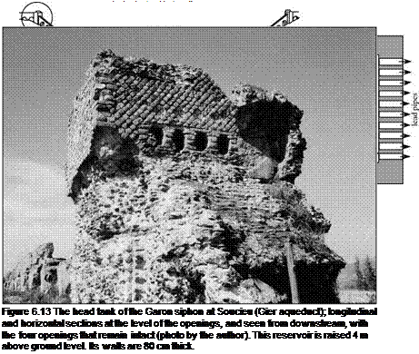
Vitruvius might call a colliviaria. Whereas at Pergamon the Hellenistic siphon has a sin­gle pipe, here we see the use of veritable batteries of parallel lead pipes. There are no less than nine pipes of average exterior diameter 23 cm (likely 18 cm interior diameter) side by side for the Dureze siphon of the Gier aqueduct, and ten for the Garon siphon (Figure 6.13). There are no remains to indicate the number of parallel conduits for the Yzeron siphon; but taking into account the large size of its reservoir, there were likely 11 or 12 similar pipes (Figure 6.40). The bridge-siphons were particularly wide at around seven meters, to support numerous parallel pipes.

The spring water conveyed by the siphons of Lyon is generally not calcareous, and therefore there is not much encrustation. An exception is the Mont-d’Or aqueduct, which does show evidence of some deposits. The aqueducts arrive into the city of Lugdunum at different elevations. It is thought that the Mont-d’Or aqueduct supplied the thermal baths whose remains have been found in the Minimes area. No traces remain of the water distribution system in the city itself, but it is likely that the conduits passing

under the Saone through siphons supplied the peninsula between the two rivers.

The Roman aqueducts in Gaul

The growth and prosperity of the period of peace between 97 and 180 AD directly ben­efits the Roman provinces. All Gallo-Roman cities of importance benefit from one or several aqueducts during this period, under the reigns of Nerva, Trajan, Hadrian, Antonius, and Marcus Aurelius, then until 235 AD under Severus. Aix-en-Provence and Lyon have four aqueducts; later on we will examine those of Lyon in detail. At Vienne, where the sources are very near,[232] we know of eleven aqueducts; at Poitiers (Lemonum) and Perigueux (Vesone), three. Some of these aqueducts are quite simple in design, with a very regular slope, as at Perigueux and Rodez. Others have quite a variable slope, most often steeper upstream than downstream, and with quite a variety of hydraulic works: tunnels, bridges, drops, siphons. The average slope itself can be quite variable from one aqueduct to another; it is usually between 0.2 and 1.6 m/km. One notable singularity is the Craponne aqueduct at Lyon, whose average slope is 16 m/km.

The dimensions and discharges of the aqueducts are also quite variable. The aque­ducts of largest cross-sectional area are at Vienne and Nimes. At Lyon and Nimes, the lengths rival those of the aqueducts of Rome itself (50 to 75 km). What is striking from the outset is, as shown in table 6.3, the diversity of configurations. Yet the dates of con­struction, when known, are most often in the 1st and 2nd centuries AD, the period of prosperity, Roman peace, and the concomitant economic climate favorable for develop­ment of the provinces. Samples of the broad panorama of Roman techniques of this period, adapted to local conditions, can be found in Gaul. We too rarely know the his­tory of these aqueducts, histories that are sometimes quite dynamic[233] as conditions change. The needs for water can increase over time, or the discharge available from the sources can decrease. Calcareous water can clog the conduits with deposits.

At Sens (Agedincum), the Fauconderie spring (on the left bank of the Vanne) is ini­tially the sole water source for the aqueduct. But when the spring dries up, four other springs are tapped successively until the flow is restored to, or slightly exceeds, the ini­tial supply. The aqueduct is increased in length from 6.1 km to 14.2 km, so as to reuse both the canal between the former Fauconderie spring and Sens, and the bridge on which the aqueduct crosses the valley of the Vanne.

At Saintes (Mediolanum), after some fifty years the capacity of the aqueduct is reduced due to the increase in roughness caused by calcium deposits. Therefore the aqueduct is completely rebuilt, being replaced by one of larger cross-sectional area but flatter slope, capturing water from new springs and delivering it to the city at a higher elevation. This reconstruction, like that of Sens, was based on re-use of large art works – the two bridges called the Arcs (27 arches, 298 m long) and the Hautmont (62 arches, 400 m long) as well as the tunnel of Neufs Puits. On these bridges, the canal is simply raised. But along underground segments, major construction efforts are devoted to mod­ification of the cross section. However, the water from new sources is even more cal­careous than the original. According to the estimates of Marcel Bailhache, the discharge, which had been increased from 4,000 to 22,600 m3/day by the reconstruction, subse­quently decreases to a value of only about 8,000 m3/day.

At Toulouse (Tolosa), the capturing of supplementary sources increases the dis­charge of the Ardenne aqueduct. But the resulting water depth (0.66 m) ends up exceed­ing the depth of the 40-cm canal lining, thus causing serious degradation of the canal walls.

Water quality is a strong determinant of the longevity of the aqueducts. If the water is calcareous, lime encrustation can reduce the flow area and increase the roughness to the point of reducing the discharge capacity by a factor of two in a few decades. Without maintenance, the canal can become completely blocked. On the other hand, if the water is not calcareous, the canals can have a very long lifetime. The aqueduct of Sens, for example, will be used up until the middle ages.

The most important works are those of Lyon and Nimes.

Table 6.3 A collection of synthesized data on the principal known Gallo-Roman aqueducts, listed in decreasing order of length.[234]

Note: The useful depth indicates the height of impermeable lining opus signinum The discharges in parentheses are those that we have been able to calculate when there is a constant slope on a sufficiently long reach, assum­ing a roughness height of 3 mm for the canal walls.

Name

Length

(km)

Avg Slope

(m/km)

Est. Max. Flow

(m3/day)

Total

Depth

(m)

Useful

Depth

(m)

Width

(m)

Remarks

Lyon:

86

1.5

15,000

1.7

1.33

0.6

4 siphons;

Gier Aq.

11 tunnels

Lyon:

70

5.3

10,000

1.4

0.94

0.55

1 siphon;

Brevenne Aq.

1.7

0.54

0.75

8 drops

continued from page 145

Name

Length

(km)

Avg Slope

(m/km)

Est. Max. Flow

(m3/day)

Total

Depth

(m)

Useful

Depth

(m)

Width

(m)

Remarks

Arles:

55

8,000

1.3

0.65

Eygalliere Aq.

Nimes

49.7

0.25

(40,000)

1.85

1.2

1.2

1

Passes over Pont du Gard

Reims

44

0.5

22,000

1.4

0.9

0.7

1

3 tunnels (800 m; 1,850 m;

(34,000)

and 900 m); regular slope

Frejus

40

12?

1.07

0.67

0.7

1

Several bridges

Beziers:

37

2,500 to

1.05

0.8

0.42

1,300 m tunnel

Gabian Aq.

5,000

Cahors

33

1.4

3,800

1.6

0.5

0.2

1

Trapezoidal section (largest

to

0.8

below the top)

Rodez

30

1.6

38,000

1.4

0.7

0.55

Terminal siphon;

(32,000)

regular slope

Lyon:

26

3.2

6,000

0.9

0.6

0.45

Two siphons

Mont-d’Or Aq.

Carhaix

27

0.3

4,000

?

0.8

0.6

800 m tunnel

Lyon:

27

16.8

8,000

?

0.6

0.5

1 double siphon; vortex

Craponne Aq.

drop shafts

Poitiers:

25

0.123

6,700

1.21

0.75

0.75

Likely dates from 2nd cen-

de Fleury Aq.

0.46

0.9

)

tury

1

Aix:

24

8

1.1

0.69

Traconnade Aq.

Metz

22

1

22,000

1.6

0.92

1.1

Bridge over the Moselle,

1300 m long and 30 m high

Narbonne:

22

1.4

8,500

1.5

1.2

0.59

Only upstream 11 km

Cabezac Aq.

known

Paris:

15.7

0.56

2,400

0.5

0.45

0.37

Water depth does not

Arcueil Aq.

exceed 0.28 m (deposits)

Sens

6.1

1

39,000

1.56

0.9

0.56

Dates from the 2nd centu-

14.2

ry;

later lengthened

Vaison-la-Romaine

12

1

0.6

Siphon under the Ouveze

Besan$on: Arcier Aq.

10.3

2

(69,000)

1.5

0.8

0.8

Toulouse: Lardenne

9.5

1

19,000

1.15

0.4

0.65

Saintes: 1st canal

5

0.85

4,000

0.5

0.5

0.2

1

Two siphons

reconstructed canal

7.5

0.87

22,600

0.7

0.45

(2 km)

Lisieux

7

0.7

0.5

Sant-Bertrand-de-

2.7

1

13,600

1.4

0.5

0.7

1

5-meter cascade

Comminges

(18,000)

Perigueux:

2

0.66

6,200

0.66

0.66

0.37

Water depth = 0.33 m

Grand-Font Aq.

(4,200)

(deposits); regular slope