Category RENOVATION 3

Replacing a Shallow Foundation

If you decide to replace a shallow foundation, begin by checking local building codes for foun­dation specs appropriate for your area. Before

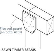
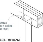
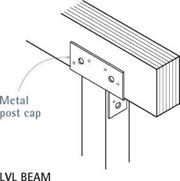
image433Подпись: Lally column capПодпись: Lally column (metal) —Подпись: (engineered lumber) (engineered lumber)Подпись: When it's necessary to construct a girder from several pieces of lumber, support each girder joint by placing a post or column beneath it. Many building codes also require metal connectors or plywood gussets at such joints to join posts to beams.

beginning foundation work, be sure to review this chapter’s earlier sections on shoring and jacking. Then survey the underside of the house and the area around the foundation for pipes, ducts, and other potential obstructions. If you can reposition jacks or move shoring slightly to avoid crushing or disconnecting drains, water pipes, and the like, do so.

Remember, jacking timbers and shoring are temporary supports. Complete the job and lower the house onto foundation elements as soon as possible. Work within your means, skills, and schedule: If you can’t afford a house mover to raise the house and replace the whole founda­tion, do it one wall at a time.

REPLACING MUDSILLS

Mudsills are almost always replaced when foun­dations are. With the framing exposed, it’s easy to install new pressure-treated or redwood mudsills that resist rot and insects. At the same time, replace rotted or insect-infested pony-wall studs. (If just a few studs are rotted, cut away the rot and nail a pressure-treated sister stud to each. If the bottom 1 in. or 2 in. of many studs has rotted, you might also install a thicker mudsill to make up for the amount you cut off stud bottoms.) If the siding is in good shape, remove just enough to expose the mudsills and rotten studs; the sid­ing holds the pony-wall studs in place and keeps them from “chattering” while you cut them.

(Pony walls shown on p. 209.) You’ll also need to punch through the siding to install temporary needle beams, discussed earlier in this chapter.

I Girder (Beam) Supports

image436

image437

Replacing a Shallow Foundation

Beam Span Comparison

Typical

joist


Header or other support


Beam Span Comparison


Beam


JOIST SPAN (x/2 + y/2)

8 FT. 10 FT. 12 FT. 14 FT. BEAM TYPE BEAM SPAN (ft.)


(2) 2×8 built-up beam

6.8

6.1

5.3

4.7

4×8 timber

7.7

6.9

6.0

5.3

3% in. x 71/2 in. glue-laminated beam

9.7

9.0

8.3

7.7

ЗУ2 in. x 71/ in. PSL beam

9.7

9.0

8.5

8.0

(2) 13/4 0=in. x 71/2in. LVL (unusual depth)

10.0

9.3

8.8

8.3

4×8 steel beam (W8 x 13 A36)

17.4

16.2

15.2

14.1


Joist span y


Header


72


Use this drawing and table for estimating beam sizes and comparing beam types for uniform floor loads of a 40-psf (pounds per square foot) live load and a 15-psf dead load. Have a structural engineer calculate your actual loads.


Beam supports 1/2 of each joist span, or x/2 + y/2. See table at right.


Replacing a Shallow Foundation

Подпись: If a new foundation section isn't terribly long or deep, use an electric demolition hammer with a shovel bit to excavate the trench. This tool is particularly helpful when there's no room to swing a pick. Shovel bits cut a nice, clean edge and dig themselves in, even in heavy clay. Then you simply shovel out the loosened soil. 1111 Подпись: Leveling a House In theory, you can level a house using individual hydraulic jacks. And if the house has only one or two low spots, you may succeed. However, the framing of a house will usually have sagged and settled, increasing the likelihood that jacking one area will raise an adjacent area too high. Heavily loaded points in multistory houses may resist being raised at all and when they finally do move, it's often sudden, loud, and frightening. Leveling a house is far more likely to succeed if done by a house mover with a unified hydraulic jacking system, in which jacks are interconnected, via hoses, to a central console that monitors the load on each jack. Thus, instead of 12 workers trying to turn 12 jacks at exactly the same time, a single operator at the console can ensure that the jacks rise at the same—or variable-rates, to the desired height. That desired height is determined beforehand by the foundation contractor, house mover, structural engineer, and—on occasion—the architect. Most often, the house mover works from a master reference point outside, against which house corners are read to determine whether they need raising or lowering. (For example, corner 1 might be listed as +3/ in.; corner 3, as -1/ in.; and so on.) Once the corners are leveled, the framing in the middle of the house is fine-tuned. Even when professionals level a structure, there's invariably damage to the finish surfaces inside, such as cracked plaster or popped drywall seams, door latches that no longer meet strike plates, trim that's askew, and windows and doors that bind during opening or shutting. Consider all this before you jack. Raising only the most out-of-level areas may be more cost-effective than leveling floors perfectly. Moreover, gently sloping floors may add character to an older house. Подпись: This old mudsill rotted out because the foundation was too close to the ground. After using a laser level to transfer the height of the new foundation, this builder snapped a chalkline across the pony-wall studs to indicate the height of the new sill.image438

Once you’ve jacked up and shored the house framing, lay out the height of the new sill by snapping chalklines across the pony-wall studs. Use a laser level to indicate where the chalk marks should go or, if the old foundation is level, measure up from it. Although the line should be as level as possible, small variations will be accommodated when the concrete is poured up to the bottom of the mudsill.

With the siding removed, use a square to extend the cutoff marks across the face of the studs; a square cut optimizes load bearing from the stud onto the mudsill. Use a reciprocating saw to make the cuts. If the first stud chatters as you attempt to cut through it, tack furring strips to all the studs, just above the cut-line to bolster successive studs. Then remove the old mudsill and rotted stud sections. Chances are the old mudsill will not be bolted to the foundation.

The replacement sill should be foundation – grade heart redwood, pressure-treated Douglas fir, or yellow pine to resist insects and moisture and should be end-nailed upward into the solid remnants of each stud, using two 16d galvanized common nails. Use a pneumatic nailer to nail up the new mudsill; it does the job quickly. However, predrill anchor bolt holes into the new
mudsills before nailing them to stud ends. Anchor bolts will secure house framing to the foundation after you pour it.

Cutting into a Concrete Floor

To enlarge an existing load-bearing pad or create one where none was, you may need to cut through a concrete floor. Depending on the condition and thickness of that floor, the job will range from nasty to horrible. Cutting concrete is noisy, dirty, and dangerous; and the tools are heavy and unpredictable. Wear safety glasses, gloves, hearing pro­tectors, and a respirator mask. Adequate ventilation and lighting are a must.

If the floor was poured before the 1950s, you’ll likely find that it is only 3 in. or 4 in. thick and is without steel reinforcing. The floor may also be badly cracked.

In this case, you can probably break through it with a pickax, but to minimize floor patching later, rent an electric concrete-cutting saw with a diamond blade to score around the opening. Then finish the cut (the saw – blade rarely cuts all the way through) with a hand sledge and a chisel.

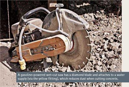
Be advised, however, that a concrete-cutting saw cuts dry and thus throws up an extraordinary amount of dust. Therefore, you may need to seal off the basement with plastic barriers and then spend an hour vacuum­ing afterward. Alternatively, you can rent a gasoline – powered wet-cut saw, which keeps down the dust but fills the basement with exhaust fumes. And, if the con­crete floor is a modern slab, 5 in. thick and reinforced

with rebar, you can spend a day accomplishing very little. Well. . . you get the picture.

Fortunately, for a few hundred bucks you can hire a concrete­cutting subcontractor to cut out a pad opening in about an hour. (Don’t forget to allow for the thickness of the form boards when siz­ing the opening.) The subcontractor can also bore holes needed for drainpipes and such.

Подпись: Before adding a girder to correct springy floors, go under the house and see if there's solid blocking or cross bridging between joists. If not, add it, and that may be all you'll have to do to stiffen the floors. If floors sag between joists, the subflooring may be too thin. 1111 Подпись:

under the post (a dab of silicone caulking will hold it in place while you plumb and position the post); then lower the jack so the new post bears the load. Or replace the wooden post with a preprimed metal column. However, if basement floors are wet periodically—suggested by sedi­ment lines along the base of walls—build up or replace the existing pad with a taller one to ele­vate the base of the post. Add a sump pump, too, as explained on p. 224.

Replacing pads. Replace concrete pads that are tilting or sinking because they are undersize for the loads they bear. Likewise, you’ll need to pour a new pad, if there was no pad originally and an overloaded post punched through the concrete floor. Pads for load-bearing columns should always be separated from floors by isola­tion joints.

Load-bearing pads should be 24 in. by 24 in. by 12 in. deep, reinforced with a single layer of No. 4 (12-in.) rebar arranged in a tic-tac-toe grid. Pads supporting a greater load (such as a two – story house) should be 30 in. by 30 in. by 18 in. deep, with two layers of no. 4 rebar; in each layer, run three pieces of rebar perpendicular to three other pieces. In either configuration, keep the rebar back 3 in. from the edges of the pad.

Line the forms with sheet plastic so that the water in the concrete won’t drain into the soil and weaken the pad. (Plastic also prevents soil moisture from later migrating through the pad and rotting the post.) If you carefully level the tops of the form boards and screed off the con­crete to them, the top of the pad will be level as well. Allow the concrete to cure before putting weight on it: 3 days minimum; 7 days recommended.

ADDING A GIRDER

Adding a girder beneath of a run of joists short­ens the distance they span, stiffens a springy floor, and reduces some loading on perimeter foundations. If your floors are springy and joists exceed the following rule-of-thumb lengths, con­sider adding a girder.

JOIST SIZE____ TYPICAL SPAN (ft.)

2 x6 8

2 x8 10

2×10 12 2×12

An engineer can size the girder for you.

"Beam Span Comparison,” on the facing page, shows maximum spans for built-up girders in two-story houses.

Ideally, the new girder should run beneath the midpoint of the joist span, but if existing ducts or drainpipes obstruct that route, avoid them by shifting the girder location a foot or two. Once you locate the girder, snap a chalkline to mark its center, and plumb down from that to mark posi­tions for pads and posts. Place posts at each end of the girder and approximately every 6 ft. along its length. If you create a girder by laminating several 2xs, keep at least one member of the "beam sandwich” continuous over each post.

Size and reinforce pads as described in the preceding section. After the pad’s concrete has cured 1 week, bring in the girder or laminate it on site from 2-in. stock. Prescribed widths for built-up girders are usually three 2x boards (4И in. thick when nailed together). For built-up girders and beams, the Uniform Building Code recommends the following nailing schedule:

20d nails at 32 in. on center at the top and bot­tom and two 20d nails staggered at the ends and at each splice.

Whether solid or laminated, if the girder has a crown, install it crown up. Installing a new girder is essentially the same as positioning a temporary shoring beam, except that the girder will stay in place. Have helpers to raise the girder and sup­port it till permanent support posts are in place. Properly sized, the pad will have more than enough room for jacks and posts, so place jack­ing posts as close as possible to the permanent post’s location. Raise the girder approximately 18 in. higher than its final position, to facilitate insertion of the new posts.

STEEL BEAMS

If there’s limited headroom or clearance under the house, steel beams provide more strength per equivalent depth than wood beams. For steel beams, hire an engineer to size them and a spe­cialist to install them: Steel I-beams are expen­sive and heavy, and they can be problematic to attach to wood framing, without special equip­ment to drill holes, spot-weld connectors, and so on. For commonly available sizes and some sense of the weights involved, see "Steel I-Beams,” on p. 53.

Needle Beams

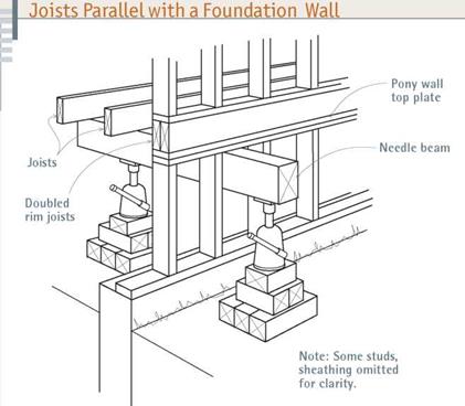
image429Подпись: Where joists run parallel to the foundation wall, remove a section of siding and run a temporary needle beam through the wall as shown. To prevent its deflection under pressure, double the rim (outer) joist and run solid blocking to the next joist inward.

When replacing a mudsill or sections of a foundation whose joists run perpendicular to that foundation wall (see p. 210), place a 4×8 or 4×10 carrying beam on edge under the house, within 2 ft. of the foundation. A jack every 6 ft. under the beam should suffice.

When joists run parallel to the foundation wall being replaced, you’ll need to run needle beams through exterior walls, and support each beam with one post underneath the house and a second post outside, roughly 2 ft. beyond the foundation wall. For this, you’ll need to remove sections of siding so you can insert a beam every 6 ft. to 8 ft. If the siding is stucco, you’ll need to punch large holes through it. To keep the rim (outer) joist from deflecting under the load, nail a second rim joist to it, doubling it before jacking. Also, add solid blocking from those doubled rim joists to the first adjacent joist. Use metal connectors to affix the blocking and 10d nails to face-nail the rim joists.

Подпись: Joists Perpendicular to a Foundation Wall
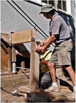
Подпись: To determine the height of the shoring posts, jack the beam to the desired height, level the footing block, and measure between the two. Nail the post cap on before inserting the post. Because this needle beam is simply holding a wall in place—not raising it—it was jacked just snug to a wall plate.image430Подпись: 2 ft. or lessПодпись: Pony wallПодпись: Support beamПодпись: MudsillПодпись: FoundationПодпись: Cribbingimage431Supporting the structure: When joists run perpendicular to the foundation wall you’re working on, support their load with a beam parallel to the wall. Allowing yourself room to work, put this beam as close to the wall as possible – in most cases, 2 ft. is optimal.

Подпись: PROnP Shoring timbers are heavy, so get help. It takes three strong workers to raise a 16-ft. 4x8. A 4x12 that same length requires four people. llll

2. Level and set the footing blocks or crib­bing on compacted soil. Each jack base should be about 2 ft. by 2 ft. Or, if you’re using a single tim­ber block, use a 4×12 at least 3 ft. long or, if the soil is crumbly, at least 4 ft. long. If you spend a little extra time leveling the footings, the posts will be more likely to stay plumb. To support a single-story house, set posts every 5 ft. or so beneath an adequately sized beam—typically, a 4×8 or 4×10 set on edge.

3. Positioning a jacking beam requires prep work. Ideally, the crew should raise the beam into place and then immediately plumb and set the jacks. But they may need to catch their breath or gather equipment before setting the jacking posts. In that event, cut two 2x4s approximately h in. longer than the distance from the underside of the beam to the top of the cribbing plates and use a sledgehammer to wedge a 2×4 under each end of the beam. Caution: This setup is inherently unstable, so workers should monitor both 2x4s continually to make sure they don’t kick out.

4. As soon as the beam is in place, cut posts 10 in. shorter than the distance from the under­side of the beam to the top of the footing blocks. This 10 in. is roughly the (closed) height of a hydraulic jack plus a little room to move. With a helper, place jacks and posts under both ends of
the beam, plumb the posts, and start jacking. Center each jack on its footing blocks so there’s plenty of room for the shoring post(s) that will follow shortly. (If you use hydraulic jacks, you can position the shoring posts 3 in. to 4 in. from the jacking posts.) As you jack, try to raise both ends of the beam evenly, using a 4-ft. or 6-ft. spirit level to check for level.

The amount you raise the beam beyond that depends on whether you’re leveling floors, taking weight off joist ends before replacing a founda­tion, or just supporting the structure where it is. When the beam is at the desired height, measure down to the tops of footing blocks to determine the height(s) of the shoring posts. (If you jack up an additional ‘/ in., you’ll find it easier to slide shoring posts in.)

5. After you’re done jacking, install the shoring posts, which are more stable than jacks on posts. To keep the shoring posts in place, nail steel caps to their tops before installing them. Once you’ve placed the posts under the footing beams, attach the post caps to the beams, and add cross bracing or plywood gus­sets to keep the beam from rotating. Once you’ve plumbed the shoring posts and braced the beams, lower the jacks slowly till they no longer bear weight, and then remove them.

With shoring supporting all necessary bearing members, you’re ready to begin repairs.

Note: Some foundation contractors install two shoring posts—one on either side of the jacking post—for greater stability. Once the jack is removed, nail two 3-ft. long 2×4 diagonal braces between the two shoring posts; for this, use a pneumatic nailer. Hammer blows could dislodge the posts.

6. When your repairs are finished, begin to remove the shoring by reinserting the jacking apparatuses and then simultaneously raising all the jacks slowly and evenly to take weight off the shoring. Leave the cross bracing in place till those loads are removed. Then, keeping the jack­ing posts plumb, carefully remove the post-and – beam bracing and carefully lower and remove those elements. Gradually lower the building onto its new pads, posts, and foundation, and then remove the jacks.

Minor Repairs and Upgrades

The category minor repairs includes anything short of replacing a failed foundation, which is covered in the next section. Repairing surface cracks is explained on p. 205.

REPLACING POSTS AND PADS

If floors slope down to a single point, there’s a good chance that a post or pad has failed. If a floor slopes down to an imaginary line running down the middle of the house, there’s probably a girder sagging because of multiple post or pad failures. Fortunately, the cures for both condi­tions are relatively straightforward.

Post repairs. The most common cause of wooden post failure is moisture wicking up through a concrete pad, rotting the bottom of the post. To replace a damaged post, use the tech­niques just described in "Jacking and Shoring.” Place footing blocks as close as possible to the existing pad, and jack just enough to take the load off the post—plus ‘/ in. Remove the rotted post, measure from the underside of the girder to the pad (remembering to subtract the ‘/ in.!), and cut a new post—preferably from pressure-treated lumber.

Подпись:To keep this new post from rotting, cut a sheet-metal plate to put under the bottom of the post; use aviation snips to cut the 22-gauge sheet aluminum. The metal will prevent moisture from seeping up through the concrete. Place the plate

image432

JACKING SAFELY

For safe jacking, you need to proceed slowly and observe the following precautions.

Preparatory steps

► Survey the building, noting structural failings and their probable causes as well as which walls are load bearing. Also determine whether joists or beams are deflecting because of heavy furniture, such as a piano; which pipes, ducts, or wires might complicate your repairs; where the gas pipe shutoff is; and so on.

► Have a plan that anticipates everything.

If excavation is necessary, who’s going to do it? And where will you put the displaced dirt? (Disturbed dirt has roughly twice the volume of compacted soil.) Will you need to rent equipment, such as jacks, compressor, and jackhammer? Where will you store materials? How will rain affect the materials and the work itself? Can a concrete-mixer truck reach your forms or will you need a separate concrete pumper, an auxiliary pump on wheels that pumps (pushes) the concrete from the mixer truck to the pour?

► Assemble safety equipment. This is mostly hard-hat work. You’ll also need safety glasses that don’t fog up, sturdy knee pads, and heavy gloves. For some power equipment, you’ll need hearing protectors. Update your tetanus shot. Set up adequate lighting that keeps cords out of your way—and, on a post near a suitable light, mount a first-aid kit.

Even though a cell phone is handy if trouble strikes, never work alone. Workers should stay within shouting distance.

► Have all necessary shoring materials on hand before you start jacking. Remember, jacks are for lifting, not supporting. Within reason, level the ground where you’ll place footing blocks or shoring plates. As soon as a section of the house is raised to the proper level, be sure to set, plumb, and brace the shoring. Hydraulic jacks left to support the structure too long may slowly "leak" and settle or—worse—kick out if bumped or jostled.

Certain conditions make raising houses diffi­cult. When foundation contractors see the fol­lowing conditions, they get a second or third opinion from engineers and house movers before bidding on a job:

► Sloping sites, unstable soil, site erosion, or excessive ground water.

► A masonry building.

► Multiple-story house or single-story dwelling with heavy materials, such as stucco exterior walls; plaster interior walls; and tile, slate, or three-layer roofs.

► Quirky framing visible in the basement, such as undersize or cut-in girders, joists running in several different directions, and multiple additions to the original structure.

► Floors that pitch in different directions or are badly out of level.

► Catastrophic foundation failures, such as foundation rotation and sinking corners.

Jacking basics

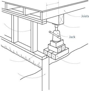
► Support jacks adequately. The footing blocks or cribbing beneath the jacks must be thick enough to support concentrated weights without deflection and wide enough to distribute those loads. It’s difficult to generalize how big such a support must be; a 4×12 footing block

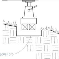
3 ft. long or two layers of 4×4 cribbing should adequately support a jack beneath the girder of a single-story house. In this case, the soil must also be stable, dry, and level. If the soil isn’t level, dig a level pit for the cribbing, as shown on p. 208. (Avoid precast concrete piers as jacking blocks because their footprints are too small and the concrete could shatter when loaded.)

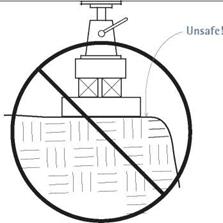
► Don’t place jacking or shoring platforms too close to the edge of an excavation. Otherwise, the soil could cave in when the timber is loaded. The rule of thumb is to move back 1 ft. for each 1 ft. you dig down. Also, don’t put jacks or shoring where they could be undermined later. For example, if you need a needle beam to support joists parallel to the foundation, excavate on either side of what will be your new foundation, and place jacking platforms in those holes. In that manner, you can remove foundation sections without undercutting the jacking platforms.

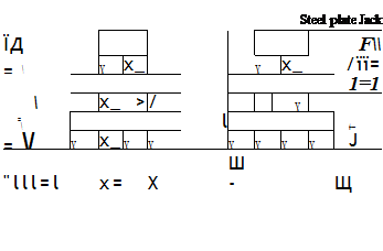
image424Подпись: Steel plate Jack ЇД F\ =  X x_ X x_ /її= 1=11  x_ > / X = l t= = V X x_ X X X X X X J — "lll=l x= X Ш- Щ Подпись: Jacks must be supported on a level, stable platform. Here, cribbing beneath the jacks and steel plates atop them disperse loads to larger surface areas. Without the steel plates to spread the load, jack heads can sink into wood beams.Подпись: FOOTING PITimage425Подпись:Подпись:

I Jacking Components

Beam

image426

Cribbing-

DON’T DO THIS!

image427

When the jack is loaded, bearing blocks placed unsafely close to the edge of an excavation can cause it to collapse.

► Level support beams, and plumb all posts. The logic of this should be evident:

When loads are transmitted straight down, there is less danger that jacks or posts will kick out, injuring someone and leaving shoring unsupported. Accordingly, cut the ends of the posts perfectly square, plumb the posts when you set them, and check them for plumb periodically as the job progresses.

Where the ground slopes, dig a level footing pit into the soil, as shown in the bottom drawings at left, so footings or cribbing can’t migrate under pressure. (Typically, the foun­dation contractor digs the pits and prepares the site before the house mover arrives to install the cribbing.) Surrounded by the walls of the pit, the bearing blocks have no place to go.

► Keep checking for level and plumb as you jack. If supports sink into the soil, posts tilt, or the jack starts "walking” under pressure, lower the jack, reset those elements and begin anew. First thing each day, check jack supports and shoring for plumb and level.

Diagonal bracing, plywood gussets, and metal connectors will each help posts stay plumb. When cross bracing temporary posts and beams, use screw guns or pneumatic nailers to attach braces. Hand nailing braces could knock posts out of plumb or cause beams to rotate or jack heads to migrate.

► Raise jacks in small increments—say,

% in. per day—to minimize damage to finish surfaces inside the house. When you’re jacking a structure to be repaired, as when replacing a mudsill, jack just enough to lift the weight off the sill to be removed. If many jacks are involved, raise them simultaneously if possible, so excessive stress (and damage) doesn’t accrue above any one jack.

Steps in jacking and installing shoring.

Setting jacking equipment varies according to the type of jack; the structural elements to be raised; and site conditions, such as ceiling height, access, and soil stability. That noted, the follow­ing observations hold true in most cases.

1. Position the jacks and jacking beams as close as possible to the joists, girders, or stud walls you’re jacking. If you’re adding posts under a sagging girder, support may be directly under the girder; but more often, it will need to be off­set slightly—say, within 1 ft. to 2 ft. of joist ends—to give you working room. In other words, close enough to joist ends so they won’t deflect, yet far back enough to let you work. Again, don’t put jacks or shoring where they could be under­mined by unstable soil later.

Patching Foundation Cracks

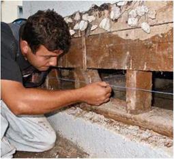
Determine the cause of the crack and fix that first; otherwise the crack may recur. Shallow foundation cracks less than % in. wide are usually caused by normal shrinkage and needn’t be patched, unless their appearance disturbs you or they leak water. However, you should repair any cracks that go all the way through the foundation: Probe with a thin wire to see if they do.

Of the many crack-repair materials, there are three main types: cement-based, epoxy, and polyurethane foams. When working with any of these materials, wear dis­posable rubber gloves, eye protection, and a respirator mask with changeable filters.

Cement-based materials such as hydraulic cement are mixed with water and troweled into cracks. To ensure a good connection, first use a masonry chisel and hand sledge to enlarge the crack; angle the chisel to undercut the crack, making it wider at the back, like a rabbet joint in woodworking. Then wire-brush the crack to remove debris. Next, dampen the surfaces, fill the crack with hydraulic cement, and feather out the edges so the repaired area is flat. Work fast because most hydraulic cement sets in 10 minutes to 15 minutes and expands so quickly that it can stop the flowing water of an active leak.

Epoxies range from troweled-on pastes to injection systems that pump epoxy deep into cracks. Application details vary, but many injection systems feature surface ports, which are plastic nozzles inserted into the crack along its length. You should space ports 8 in. apart before temporarily capping them. Then seal the wall surface with epoxy gel or hydraulic cement, which acts as a dam for the epoxy liquid you’ll inject deep into the wall through the ports. Working from the bottom, uncap each surface port, insert the nozzle of the applicator, and inject epoxy till it’s visible in the port above. Cap the port just filled, and then move up the wall, port by port.

Epoxy is famously strong. The manufacturer of Simpson Crack – Pac™ claims that its injected epoxy achieves 11,000 psi com­pressive strength when cured for 7 days. (Foundation concrete averages 3,000 psi to 4,500 psi.)

Consequently, injected epoxy, which bonds to both sides of the crack, is a true structural repair, not just a crack filler. There are a couple of disadvantages: cost and curing time. Epoxy takes hours to harden, so it can ooze out the back of the crack, if there’s a void between the soil and the founda­tion wall—as there often is. If your main concern is water leaks and not structural repairs, polyurethane foam is probably a better choice.

Polyurethane foam is applied in many ways, including the surface-port injection just described for epoxies. Polyurethane sets up in minutes, so it’s unlikely to sag or run out the back of the crack. It’s largely unaffected by water, so you can inject it into a damp crack. Unlike epoxy or cement-based fillers, polyurethane is elastomeric (meaning it stays flexible), so it’s great for filling foundation cracks that expand and contract seasonally. One disadvantage is that it has little compressive strength and hence does not create a structural repair.

Подпись:

beams, stick with wood posts: Fir 6x6s are less likely to migrate than steel columns.

Cribbing. Cribbing refers to a framework of usually squared timber (often 6x6s) stacked perpendicular in alternate layers to create a sta­ble platform for jacking or shoring house loads. In earthquake country, foundation contractors "shear wall” cribbing higher than 8 ft.—that is, they temporarily nail h-in. plywood to the crib­bing, using duplex nails. The precaution is worth the trouble: in 1989 a California house resting on 13-ft.-high shear-walled cribbing remained standing through a 7.1 quake.

Braces and connectors. To keep posts plumb and prevent structural elements from shifting, builders use a variety of braces and connectors such as these:

► Diagonal 2×4 braces 3 ft. or 4 ft. long are usually nailed up with double-headed nails for easy removal.

► Plywood gussets are acceptable if space is limited.

► Metal connectors such as Simpson hurricane ties, post caps, and post-to-beam

connectors are widely used because they are strong and quick to install.

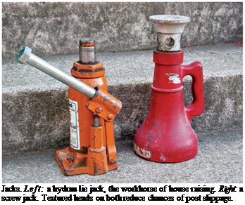
Jacks. House-raising screw jacks and hydraulic jacks are by far the most common types. For safety, all jacks must be placed on a stable jack­ing platform and plumbed.

Screw jacks vary from 12 in. to 20 in. (closed height), and extend another 9 in. to 15 in. Never raise the threaded shaft more than three-quarters
its total length because it would be unstable beyond that. Screw jacks are extremely stable: Of all types, they are the least likely to fail or lower unexpectedly under load. But they require a lot of muscle and at least 2 ft. of space around the jack for operation.

Hydraulic jacks are the workhorses of founda­tion repair and are rated according to the loads they can bear, such as 12 tons. In general, hydraulic jacks are easier to operate than screw jacks, and they fit into tighter spaces. They are lowered by turning a release valve and so can’t be lowered incrementally. Because hydraulics release all at once, many house movers use hydraulics to raise a house and screw jacks to lower it gradually.

Because the head of a hydraulic jack is rela­tively small, you need to place a 4-in. by 4-in. by f4-in. steel plate between it and the wood it sup­ports so the head doesn’t sink in during jacking. Safety note: Before lowering the jack, have a helper remove the steel plate as pressure is released. Otherwise, the plate could fall and injure the jack operator. Alternatively, have the plate predrilled so you can screw or nail it to the underside of the beam.

image423

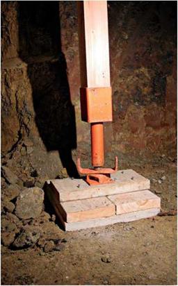
Unsafe! Although post jacks such as this are widely used as temporary shoring, they are not strong enough for house loads. Here footing blocks are also undersize, and the post is badly out of plumb.

Unsuitable for raising a house. Postjacks employ a screw mechanism but are of flimsier construction than the compact screw jack described in the previous section. They tend to be fashioned from lightweight steel, with slender screws that could easily distort when loaded beyond their capacity. So use post jacks only for low-load, very temporary situations.

Jacking and Shoring

Jacking refers to raising or lowering a building so you can repair or replace defective framing or failed foundations or to level a house that has set­tled excessively. Shoring refers to a temporary system of posts, beams, and other structural ele­ments that support building loads. Temporary is the crucial word: Shoring supports the building between jackings. Once repairs are complete, you need to lower the house and remove the shoring as soon as possible. If repairs are extensive—say, replacing foundation sections—have a structural engineer design the new sections; specify jack size; and specify the posts, beams, and bracing needed to safely jack and shore the building.

Jacking a house is nerve-wracking. It requires a deep understanding of house framing and how structures transfer loads. It also requires superb organizational skills and a lot of specialized equipment. For that reason, foundation contrac­tors routinely subcontract house-raising to house movers who have crews who know what they’re doing and have on hand thousands of cribbing blocks, scores of hydraulic jacks, and cranes to lift steel I-beams for bigger jobs. Structural engi­neers will usually know qualified house movers. (By the way, these specialists are still called house movers even when the house stays on the site.)

INDOOR SYMPTOMS OF FOUNDATION FAILINGS

image418

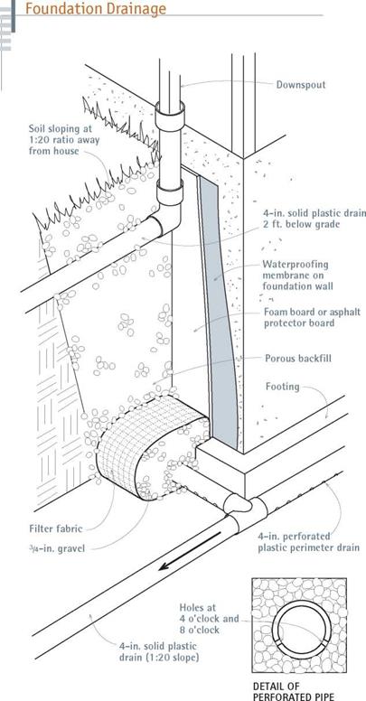
Подпись: Widespread springiness in floors and joists sag-ging in mid-span are caused by joists too small Подпись: Localized springiness or low spots in flooring are probably caused by an undersize pad or by a deteriorated or absent post beneath a girder. If you find wet rot or insect damage at the base of the post, correct that situation first. Подпись: If you're willing to excavate, you can retrofit a first-rate drainage system such as this.

Most foundations that fail were poorly designed, poorly constructed, or subjected to changes— especially hydrostatic pressure or soil movement —that exceeded their load-bearing capacities. Exact causes are often elusive.

Подпись: PROTIP If you're not sure that a foun-dation crack is active (moving), epoxy a small piece of glass to both sides of the crack. If the glass breaks, the crack is active. A glass microscope slide is per-fect for this test. Or substitute a scrap of window glass. 1111 image419Подпись:for a span or by a failed or absent girder. If an existing girder seems sound, adding posts or new pads may fix the problem. Otherwise, add a girder to reduce the distance joists span.

Flooring that crowns above a girder, sloping downward toward the outside walls; doors and windows that are difficult to open; and cracking at the corners of openings are often caused by a failure of all or part of the perimeter foundation.

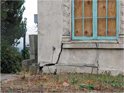
Foundation cracks often signal foundation fail­ure. Cracks may range from short surface cracks to through-the-wall cracks that should be exam­ined by a structural engineer. Here are some common symptoms and remedies:

► Narrow vertical or diagonal surface cracks with aligned sides are likely caused by foundation settlement or soil movement but are probably not serious. If water runs from cracks after a storm, fill cracks with an epoxy cement, and then apply a sealant.

► Wide cracks in foundations less than 2 ft. tall indicate little or no steel reinforcement, a common failing of older homes in temperate climates.

► Large, /і-in. or wider, vertical cracks through the foundation that are wider at the top usually mean that one end of the foun­dation is sinking—typically at a corner with poor drainage or a missing downspout.

► Large vertical cracks through the foundation that are wider at the bottom are usually caused by footings that are too small
for the load. You may need to replace or reinforce failed sections.

► Horizontal cracks though a concrete foundation midway up the wall, with the wall bowing in, are most often caused by lateral pressure from water-soaked soil. This condition is common to uphill walls on sloping lots.

► Concrete-block walls with horizontal cracks that bulge inward are particularly at risk because block walls are rarely reinforced with steel. If walls bulge more than / in. from vertical and there’s a chronic water problem, foundation failure may be imminent.

► In cold climates, horizontal cracks through the foundation, just below ground level, are usually caused by adfreezing, in which damp soil freezes to the top of the foundation and lifts it. If these cracks are accompanied by buckled basement floors, the foundation’s footings may not be below the frost line for your region.

Gaps between the chimney and the house are usually caused by an undersize chimney pad. If the mortar joints are eroded, too, tear the chim­ney down and replace it.

IMPORTANT ELEMENTS

In many parts of North America, building codes don’t require steel reinforcement in concrete foundations, but steel is a cost-effective means of avoiding cracks caused by lateral pressure on foundation walls.

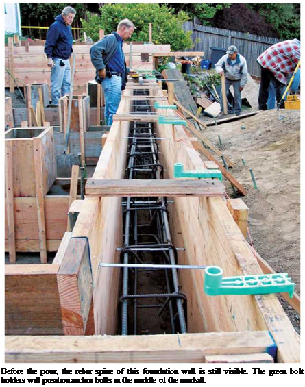
Steel reinforcement and fasteners. Steel re­inforcing bar (rebar) basically carries and distrib­utes loads within the foundation, transferring the loads from high-pressure areas to lower-pressure areas. It thereby lessens the likelihood of point failure, either from point loading above or from lateral soil and water pressures. Anchor bolts or threaded rods, tied to rebar, attach the overlying structure to the foundation. Steel dowels are usu­ally short pieces of rebar that pin foundation walls to footings, new sections to existing foun­dations, and so on.

There are also a number of metal connectors— such as Simpson Strong-Ties—that tie joists to girders, keep support posts from drifting, and hold down mudsills, sole plates, and such.

Several are shown in Chapter 4.

Quality. Concrete quality is critically important, both in its composition and in its placement. Water, sand, and aggregate must be clean and well mixed with the cement. Concrete with com­pressive strength of 2,500 psi to 3,500 psi (pounds per square inch) is common in residential founda-

THE FOUNDATION WltnlP

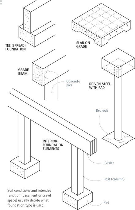
Most perimeter foundations have a companion foundation within, consisting of a system of girders (beams), posts (columns), and pads that pick up the loads of joists and interior walls and thus reduce the total load on the perimeter foundation. By adding posts, beams, and pads, you can often stiffen floors, reduce squeaks, avoid excessive point loading, support new partitions, and even avoid replacing a mar­ginally adequate perimeter foundation.

image417GETTING THE

Learn what you can about local soil conditions before hiring a soils engineer. Start with local builders—especially those who’ve worked on nearby properties. Next consult with building and land-use departments, for many have maps indicating watersheds, slide zones, contaminated soil, and the like. Finally, the U. S. Department of Agriculture (USDA) has extensive soil maps. And the U. S. Geological Survey (USGS) topographic (topo) maps show streams, lakes, flood plains, and other natural features that could have an impact on your site.

tions, yet there are many ways to achieve that strength, including chemical admixtures. Discuss your needs with a concrete supplier who’s famil­iar with soil conditions in your area, and read "Ordering Concrete,” on p. 222.

Drainage. The drainage system is not technically a part of the foundation, but the flow of water alongside and under a foundation is important to its success. In some soils, it’s essential to mediate water flow. At the very least, water seeping through foundations can cause damp basements and encourage mold. Worse, excessive water can rot framing, undermine footings, and cause un­reinforced foundations to crack, bulge inward, or fail altogether. Often moisture problems can be mitigated simply by keeping gutters and downspouts clear, grading the soil away from the foundation, and improving drainage around basement window wells. Beyond that, the "cures” are increasingly expensive, such as excavating along the outside of the foundation to add gravel and perimeter drainpipe and to apply water­proofing treatments.

Foundations and Concrete

Подпись: wood underpinning above the soil so it doesn't rot or get eaten by insects. And it should be sturdy enough to keep walls plumb and floors level despite wind, water, soil movement, and earthquakes. FOUNDATION TYPES Foundations should be appropriate to the site. For example, on sandy well-drained soil, unmortared stone foundations can last for centuries. But an unstable clay hillside may dictate an engineered foundation on piers extending down to bedrock. The tee, or spread, foundation is perhaps the most commonly used type, so named because its cross section looks like an inverted T. It's remark- Foundation issues

before starting extensive remedial work, such as replacing failed foundation sections or adding a second story to your house, have a structural engi­neer evaluate your foundation. In addition, bring in a soils engineer if the site slopes steeply or if the foundation shows any of the following dis­tress signs: bowing, widespread cracking, uneven settlement, or chronic wetness. Engineers can also assess potential concerns such as slide zones, soil load-bearing capacity, and seasonal shifting.

An Overview

A foundation is a mediator between the loads of the house and the soil on which the foundation rests. A well-designed foundation keeps a house’s

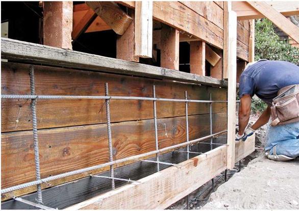
These concrete forms are half complete, showing oiled inside form boards, a new mudsill nailed up, and the bottom outer form board in place. Rebar, as shown, will be wire – tied to anchor bolts after they’ve been inserted into predrilled holes in the mudsill.


image413

Подпись: Foundation Typesimage414Подпись: Pouring VERSUS PLACING CONCRETE Every trade has its jargon. Concrete snobs, for example, insist on using the phrase placing concrete, though concrete coming out of a 4-in. hose looks more like a pour, albeit a sluggish one. Perhaps "placers" want to emphasize that concrete is so weighty that you should place it as close to its final location as possible. Point taken. But to denote the general movement of concrete from truck to forms, pour us a tall one.

ably adaptable. On a flat site in temperate regions, a shallow tee foundation is usually enough to support a house, while creating a crawl space that allows joist access and ventilation.

Where the ground freezes, foundation footings need to be dug below the frost line, stipulated by local codes. Below the frost line, footings aren’t susceptible to the potentially tremendous lifting and sinking forces of freeze-thaw cycles in moist soil. (Thus most houses in cold climates often have full basements.)

When tee foundations fail, they often do so because they’re unreinforced or have too small or too shallow a footprint. Unreinforced tee founda­tions that have failed are best removed and replaced. But reinforced tees that are sound can be underpinned by excavating and pouring larger footings underneath a section at a time.

Slab on grade is a giant pad of reinforced con­crete, poured simultaneously with a slightly thicker perimeter footing that increases its load­bearing capabilities. Beneath the slab, there’s typically a layer of crushed gravel and sheet plastic over that to prevent moisture from wicking up from the soil. Slabs are generally installed on flat lots where the ground doesn’t freeze because, being above frost line, shallow slabs are vulnerable to frost heaves. Although shallow, the large footprint of a slab sometimes makes it the only feasible foundation on soils with weak load-bearing capacity. Because slabs sit on grade, their drainage systems must be meticulously detailed.

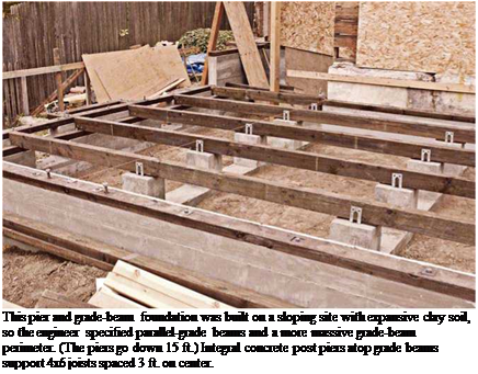
Drilled concrete piers in tandem with grade beams are the premier foundation for most situations that don’t require basements. These foundations get their name because pier holes are typically drilled to bearing strata. This foun­dation type is unsurpassed for lateral stability, whether as replacement foundation for old work or for new construction. Also, concrete piers have a greater cross section than driven steel piers and hence greater skin friction against the soil, so they’re much less likely to migrate. The stability of concrete piers can be further enhanced by concrete-grade beams resting on or slightly below grade, which allow soil movement around the piers, without moving the piers.

The primary disadvantages of drilled concrete piers are cost and access. In new construction, a backhoe equipped with an auger on the power takeoff requires 10 ft. or 12 ft. of vertical clear­ance. Alternatively, there are remote-access portable rigs that can drill in tight quarters, even inside existing houses, but they are labor inten­sive to set up and move, increasing the cost.

Подпись: This pier and grade-beam foundation was built on a sloping site with expansive clay soil, so the engineer specified parallel-grade beams and a more massive grade-beam perimeter. (The piers go down 15 ft.) Integral concrete post piers atop grade beams support 4x6 joists spaced 3 ft. on center. Подпись: Before the pour, the rebar spine of this foundation wall is still visible. The green bolt holders will position anchor bolts in the middle of the mudsill. Driven steel pilings are used to anchor founda­tions on steep or unstable soils. Driven to bedrock and capped, steel pilings can support heavy vertical loads. And, as retrofits, they can stabilize a wide range of problem foundations. There are various types of steel pilings, including helical piers, which look like giant auger bits and are screwed in with hydraulic motors, and push piers, which are hollow and can be pushed in, strengthened with reinforcing bar, and filled with concrete or epoxy.
Openings in Brick Walls

If you want to add a door or window to a brick wall, hire a structural engineer to see if that’s feasible. If so, hire an experienced mason to create the opening; this is not a job for a novice. If the house was built in the 1960s or later, the wall will likely be of brick veneer, which can be relatively fragile because the metal ties attaching a brick veneer to wood – or metal-stud walls tend to rust out, especially in humid or coastal areas. In extreme cases, steel studs will rust, and wood studs will rot. Thus, when opening veneer walls, masons often get more of a challenge than they bargained for.

Brick homes built before the 1960s are usually two wythes thick (with a cavity in between), are very heavy, and have very likely settled. Undisturbed, such walls may be sound; but openings cut into them must be shored up during construction, adequately supported with steel lintels, and meticulously detailed and flashed. Moreover, openings that are too wide or too close to corners may not be feasible, so a structural engineer needs to make the call.

To close off an opening in a brick wall, remove the window or door and its casings, and then pry out and remove the frame. Prepare the opening by toothing it out—that is, by remov­ing half bricks along the sides of the opening and filling in courses with whole bricks to dis­guise the old opening. The closer you can match the color of the existing bricks and mortar, the better you’ll hide the new section. As you lay up bricks, set two 6-in. corrugated metal ties in the mortar every fourth or fifth course, and nail the ties to the wood-frame wall behind. Leave the steel lintel above the opening in place.

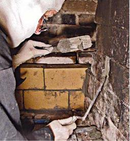
Build up. The rest is basic bricklaying technique. String a bed of mortar as wide as the edge of a firebrick across the back of the firebox and press the bricks firmly into it, working from one side to the other. Bricks should be damp but not wet. Butter the ends of each brick to create head joints, and when you’ve laid the first course, check for level. Use the handle of your trowel or mason’s hammer to tap down bricks that are high. Typically, you’ll need to cut brick pieces on each side of the back wall, to "tooth into” the staggered brick joints on the sidewalls, but that step can wait till the back wall is complete. As you lay up each course of firebrick, lay up the rubble brick courses, which needn’t be perfect, nor do you need to point their joints.

Unless yours is a tall, shallow Rumford fire­place, firebricks in the back wall should start tilt­ing forward by the third or fourth course. To do that, apply the mortar bed thicker at the back. Build up the firebox and rubble-brick walls till you reach the throat opening. Then fill in any space between the firebox and rubble-brick walls with mortar, creating a smoke shelf. The smoke shelf can be flat or slightly cupped.

Once the back wall is up, fit piece bricks where the back wall meets sidewalls. Clean and repoint the mortar joints as needed. With a mar­gin trowel serving as your mortar palette, use a tuck-pointing trowel to "cut” a small sliver of mortar and pack it into the brick joints. Allow the mortar to dry a month before building a fire. Make the first few fires small.

image408

After cutting back deteriorated mortar joints, pack them with fresh mortar. Fill a margin trowel with refractory mortar, as shown. Then use a thin tuck­pointing trowel to scrape mortar from it into the joint. Refractory cement is so sticky that it will cling to the margin trowel’s blade even if held vertically.

image409image410image411Dressing Up a Concrete Wall

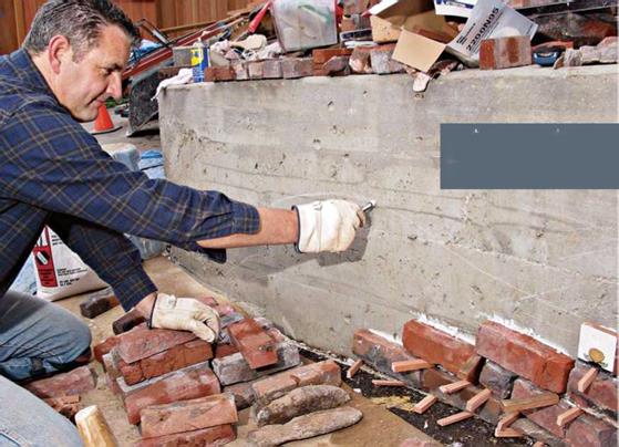
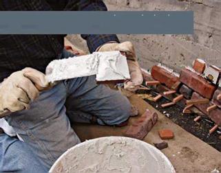
If you’re bored with the drab band of foundation concrete around the bottom of your house, dress it up with a glued-on brick or stone facade. A number of adhesive materials will work well.

In the project shown here, the mason used SGM Marble Set™, intended for marble or heavy tiles, but epoxies would work too. Whatever adhesive you choose, check the manufacturer’s instructions for its suitability for exterior use in your area, especially if you have freezing winters. Use exterior-grade bricks, too.

How traditional or freeform you make the facade depends on your building’s style and your sense of fun. The clinker brick, tile, and stone facade shown completed on p. 182 nicely complemented the eclectic style of the Craftsman house. It would probably also look good on the foundation of a rambling brown shingle, a Gothic revival house, or a more whimsical sort of Victorian.

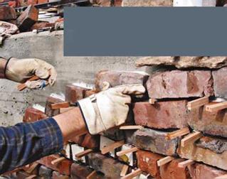
Not relying on mortar joints to support the courses gives you a cer­tain freedom in design, but it’s still important that you pack joints with mortar and compress them with a striking tool so they shed water— especially if winter temperatures in your region drop below freezing.

Todays masonry adhesives are so strong that they can adhere heavy materials—such as brick, stone, and tile—directly to concrete. Freed from needing to support much of anything, mortar joints can be as expressive as you like.

Подпись: Butter the backs of masonry elements with adhesive, in this case, a mortar designed to adhere marble and heavy tile to concrete.Use short sticks to space bricks, stones, and tiles. Thi prevents what little slippage may occur before the adhesive sets and creates a joint wide enough to pac mortar into. Compress and shape the mortar to mak it adhere and keep the weather out.