Category RENOVATION 3

Using a Voltage Tester

Two-prong voltage testers are inexpensive, reliable, and available almost everywhere. Whatever tester you use, first test the tester on a circuit that you know is energized.

If the tester doesn’t indicate voltage on that circuit, the tool may be broken.

Testing Receptacles

When testing receptacles, grasp the insulated part of the tester and insert its probes into the receptacle slots. Never touch the bare wire tips of tester probes. If the tester lights up, there’s voltage present. Have a helper at the service panel flip circuit breakers (or remove fuses) till you find the one that controls the outlet and the tester light goes out. Use cell phones to communicate, which sure beats scream­ing between floors.

If the receptacle is faulty or a wire is loose, however, the previous test may not detect voltage present in the outlet box. To be certain, unscrew the receptacle cover plate and the two screws holding the receptacle to the outlet box.

Pull the receptacle out from the wall, being careful not to touch the wires, receptacle screw terminals, or metal outlet boxes. Touch the tester probes to screws on opposite sides of the receptacle (gold on one side, silver on the other). Then touch the tester probes to the bared wire ends on the opposite sides (black wires will connect to gold screws, white wires to silver ones). As a final test, touch the tester to the black wire ends and to the metal box.

Testing Fixtures

Remove a fixture by unscrewing the long machine screws holding it to the outlet box. Carefully pull the fixture out from the box. Test the screw terminals on the underside of the fixture as just described for receptacles. If a switch controls the fixture, test it as described in the next section. Unscrew the wire nuts, if any (support the fixture so it can’t fall), and then touch the tester probes to the exposed wires.

Testing Switches

To identify the circuit that serves a particular switch, turn on the fixture it controls and have a helper at the service panel flip breakers until the light goes out. If that test is inconclusive or you aren’t sure the switch is operable, remove the cover plate and the two screws holding the switch to the box. Test the wires leading to the switch:

Подпись:Подпись: To see if a receptacle is hot (energized), insert the voltage tester probes as show Here, the tester’s light indicates that the outlet is hot. Always check a tester fii on an outlet that you know is hot, to be sure the tester is working correctly.Подпись: 1Подпись: ‘ -Zr,image472Be careful not to touch the screws on the side of the switch or the wires leading to them. Switches interrupt hot wires, so apply the tester probes to each screw on the switch as well as to any group of wires spliced together.

Volts, Amps, and Watts

At a power plant or a substation, electricity is multiplied (charged) and given pressure (voltage); in that form, electricity is potential energy, just like a charged battery. When electricity is put to work at an outlet, electrons flow through the wires, and power is delivered as heat or light. Amperes (amp) is the measure of this current flow. The amount of energy consumed at a given point-say, at a toaster or a light bulb-is measured in watts. Volts, amperes, and watts are thus interrelated:

► Voltage: the potential to do work (electrical pressure).

► Amperes: the rate of electrical flow.

► Watts: the rate at which energy is consumed.

Or, expressed as mathematical formulas:

watts = voltage x amperes amperes = watts * voltage

To reiterate briefly, electricity, impelled by voltage, flows from the power source. Along the way, at outlets, it encounters resistance and does work. It then returns to the power source, its voltage reduced or spent.

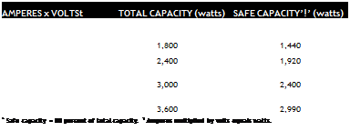
Подпись: PROTiP The utility company will install cables to the building and will install the meter. The homeowner is responsible for everything beyond that, including the meter base and entrance panel, which a licensed electrician should install. Подпись: ■ illПодпись: AMPERES x VOLTSt TOTAL CAPACITY (watts) SAFE CAPACITY’!’ (watts) 15 x 120 1,800 1,440 20 x 120 2,400 1,920 25 x 120 3,000 2,400 30 x 120 3,600 2,990 * Safe capacity = 80 percent of total capacity. t Amperes multiplied by volts equals watts. Note: If someone has unwisely oversized a breaker, you can’t use breaker size to calculate the circuit’s capacity. If you suspect oversizing, hire an electrician to remove the panel cover and determine the size of the circuit wires used. In general, lighting circuits with 14AWG wire should be protected by a 15-amp breaker. Small – appliance circuits with 12AWG wire should be protected by a 20-amp breaker. Most large 240-volt appliances require 10AWG wire, pro­tected by a 30-amp breaker. Always check appli­ance nameplates for amperage ratings.

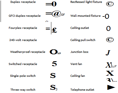
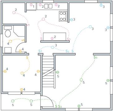
Подпись: Common Electrical SymbolsПодпись: Duplex receptacle =0 RecRessed light fixture © GFCI duplex receptacle =@GFCI Wall-mounted fixture -0 Fourplex receptacle =$ £ Ceiling outlet 0 240-volt receptacle Ceiling pull switch © Weatherproof receptacle OWP Junction box J Switched receptacle 5 Vent fan XVF Single-pole switch S Ceiling fan X3CF Three-way switch S3 Telephone outlet ► Подпись: Symbols for Mapping House Circuits Numbers indicate separate circuits, or you can use colored markers to differentiate circuits. Dashed lines link switches and the fixture (or receptacles) they control. (Note: “S3" indicates three-way switches, not a circuit number.) image470MAPPING THE SYSTEM

Mapping the entire system, including old and new circuits, lets you quickly match outlets, switches, and fixtures to circuits; this is especial­ly helpful later if a circuit breaker trips (or a fuse blows). At the entrance panel, assign a number to each circuit. Then, as a helper flips breakers or removes fuses, map the outlets controlled by each circuit. To save shouting between floors, use cell phones.

Tools and Materials

All tools and materials should bear the Under­writers’ Laboratory (UL) stamp, which indicates that a component meets the safety standards of the electrical industry.

TOOLS

You don’t need a lot of expensive tools to wire a house successfully. All tools should have insulat­ed handles. Avoid touching the uninsulated parts of tools when they’re near potentially hot (ener­gized) wiring.

► Wear safety glasses for all tasks that throw up debris, such as cutting through finish materials, drilling, and notching studs. Wearing rubber gloves and using insulated tools can also save your life. But the greatest safety aid is the voltage tester shown on the facing page.

► In addition to electrical testers, you should have a continuity tester, which tests wire runs and connectors for short circuits or other wiring flaws—before a circuit is connected to power.

► A multipurpose tool is used to strip individual wires of insulation, cut wire, crimp connections, and quickly loop wire around device screws.

► Lineman’s pliers are the workhorse of an electrician’s toolbox. They can cut wire, hold wires fast as you splice them, and twist out box knockouts.

► Needle-nose (long-nose) pliers can grasp and pull wire in tight spaces. These pliers can loop wire to fit around receptacle and switch screws. But don’t use the tool for heavy twist­ing because that can misalign its jaws.

► Diagonal-cutting and end-cutting pliers can cut wires close in tight spaces; end cutters (sometimes called nippers) also pull out staples easily.

► Screwdrivers should always have insulated handles. Get several sizes of slot – head and Phillips-head screwdrivers, plus an offset screwdriver and a nut driver.

Planning and Estimating

The scope of a renovation is always a trade-off between what you’d like and what you can afford. Oversizing the system slightly to accommodate future needs is usually money well spent.

Assess the existing system, see what local codes require, calculate future needs, and then map out an upgrade.

ASSESSING THE PRESENT SYSTEM

To assess the situation, start with two questions: Is the electrical system safe? and Is it adequately sized?

Is it safe? Hire a licensed electrician or a qual­ified home inspector to assess the electrical system and advise you about what needs doing. But before the electrician shows up, do a little hands-off looking for yourself and try to answer the following questions:

► Is the entrance panel grounded? There should be a large grounding wire running from the panel and clamped to a cold-water pipe and/or a grounding rod.

► Is there equipment grounding? Grounding the panel is not enough. For the entire electrical system to be grounded, there must be continuous ground wires running to every device in the house. If there is only two-wire service to the house and you see only two-hole receptacles in use, the system is outdated and has no equipment grounding.

► Do bathrooms, kitchens, garages, and outdoor outlets have GFCI receptacles, as required by the NEC?

I Major Grounding Elements

► Is the equipment in good shape? Rusty entrance panels, receptacles encrusted with paint, and wires with cracked or frayed insulation are as unsafe as they are unsightly.

► Is the service panel installed in a wet or damp area? This situation is extremely unsafe. In fact, many electricians refuse to examine service panels if there’s standing water nearby.

► Is present usage safe? Installing fuses too big for a circuit to prevent blown fuses is a fool’s bargain, as are overloaded receptacles, extension cords under carpets, and the like.

Is it adequate? If you’ve lived in the house for a while, you’ll have a fair idea of whether the sys­tem is big enough.

► Are there enough outlets, or do receptacles teem with multiplug and extension cords? If so, plan to add more receptacles where needed.

► Do you blow fuses often, especially when starting up small appliances or power tools? Does your TV screen shrink momentarily when the refrigerator motor or the water

Подпись: Calculating Total Electrical Load

General-use circuits:

_____________ sq. ft. x 3 volt-amp/sq. ft.

Small-appliance circuits:

_____________ 20-amp circuits x 1,500 volt-amp

Laundry circuit

(1,500 volt-amp each)

pump kicks in? These symptoms may indicate a system that’s close to its present limits.

► How many cables run from the utility pole to the house? If there are only two large cables, the electrical service is probably inade­quate. As explained in"Electricity in the House,” on p. 227, a two-wire service delivers only 120-volt service; whereas a three-wire service delivers 120-volt and 240-volt service.

► What is the panel rating on the name­plate? If there’s a two-wire service, the panel is probably rated for 30 amps. These days, a 100-amp entrance panel is considered minimal; a 200-amp panel can accommodate future uses.

Подпись: Major appliances/dedicated circuitsGENERAL CODE REQUIREMENTS

Water heater

Cooktop/oven or range ___________________

Garbage disposal ___________________

Dishwasher ___________________

Microwave ___________________

Other ___________________

Subtotal for all major appliances *

Note: volt-amp (volt-amperes) = volts x amperes. Asterisks (*) indicate subtotals for distinct groups.

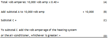
Add the asterisked subtotals of each circuit group. Then multiply any volt-amperes greater than 10,000 by 0.40 (because not all outlets are drawing energy at the same time).

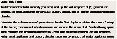
Подпись: Total volt-amperes: 10,000 volt-amp x 0.40 = (A) Add subtotal A to 10,000 volt-amp + 10,000 (B) Subtotal C = (C) To subtotal C add the volt-amperage of the heating system or the air-conditioner, whichever is greater: + (D) Подпись: Total volt-amperes = To convert this total volt-amperes to amperes, divide by volts: volt-amp-^240 volts = amp Подпись: Using This Table To determine the total capacity you need, add up the volt-amperes of (1) general-use circuits, (2) small-appliance circuits, (3) laundry circuit, and (4) major-appliance/dedicated circuits. Calculate the volt-amperes of general-use circuits first, by determining the square footage of the house; measure outside dimensions and include the areas of all finished living space. Then multiply the area in square feet by 3 volt-amp to obtain general-use volt-amperes. Assign small-appliance and laundry circuits 1,500 volt-amp each. All major appliance nameplates list amperage ratings.

Licensed electricians use NEC (National Electrical Code) formulas to size a house’s electri­cal load. Here’s an overview of NEC requirements.

General purpose.

► Keep lighting and appliance circuits separate. Calculate lighting loads at 3 watts per square foot, or roughly one 15-amp circuit for every 500 sq. ft. of floor space. When laying out the lighting circuits, do not put all the lights on a floor on one circuit. Otherwise, should a breaker trip, that entire floor would be without power.

► General-use circuits are intended primarily for lighting, but small users such as TVs, record players, and vacuums are allowed, as long they don’t exceed the capacity of the circuit. Though 14AWG wire is sufficient for lighting and switch runs, electricians often run 12AWG wire on general-use circuits to accommodate future uses.

► There must be a receptacle within 6 ft. of each doorway, and no space along a wall in a habitable room should be more than 6 ft. from a receptacle. Any wall at least 2 ft. wide must have a receptacle; and a receptacle is required in hallway walls 10 ft. or longer.

► The NEC does not specify a maximum number of outlets on a residential lighting or appliance circuit, though local jurisdictions may. Figure roughly 9 outlets per 15-amp circuit and 10 outlets per 20-amp circuit.

► There must be at least one wall switch that controls lighting in habitable rooms, the garage, and storage areas (including attic and basement). And there should be a switch near each outdoor entrance. Three-way switches are required at each end of corridors and at the top and bottom of stairs with six steps or more.

► All new 15-amp and 20-amp circuits in bedrooms must have AFCI breaker protection.

Kitchens and bathrooms.

► The NEC requires GFCI protection in the following locations: all bathroom receptacles; all receptacles serving kitchen counters;

all outdoor receptacles; accessible basement or garage receptacles; and receptacles near pools, hot tubs, and the like. (Check the current NEC for a complete listing.)

► Bathroom receptacle outlets must be supplied from a 20-amp, GFCI-protected circuit with no other outlets. However,

the NEC allows the circuit to supply required receptacles in more than one bathroom.

► There must be at least two 20-amp small-appliance circuits in the kitchen.

No point along a kitchen countertop should be more than 2 ft. from an outlet. Every counter at least 12 in. wide must have a receptacle.

► All critical-use stationary appliances must have their own dedicated (separate) circuits: water pump, freezer, refrigerator, oven, cooktop, microwave, furnace and/or whole-house air-conditioning unit, garbage disposal, window air-conditioners, and water heater.

► If a cable does not attach directly to an appliance, its receptacle must be within 6 ft. of the appliance.

CAN YOU ADD OUTLETS TO A CIRCUIT?

If there’s room in the service panel for additional breakers or fuses, adding circuits is largely a mat­ter of running cable and making good mechani­cal connections along the way. Have a licensed electrician connect new cable runs to the panel.

o To add outlets to a circuit, you must dis­connect the power from an existing outlet and fish new cable from it, as described on p. 261.

But first determine the load-bearing capacity of the circuit you want to extend.

Begin by identifying the circuit breaker (or fuse) controlling the circuit: (^) Turn off the elec­tricity to that circuit and test to be sure it’s off. Note the rating of the breaker. If it’s a general – purpose circuit, the breaker will probably be 15 amps or 20 amps. A circuit controlled by a 15-amp breaker has a capacity of 1,800 watts (15 amps x 120 volts); a 20-amp breaker,

2,400 watts. The total wattage of all energy users on the newly extended circuit must not exceed these capacities; otherwise, you risk overheating wires. To avoid overloading, load is calculated at 80 percent of capacity. For example, 80 percent
of 1,800 watts is 1,440 watts for a 15-amp circuit; 80 percent of 2,400 watts equals 1,920 watts for a 20-amp circuit. As a rule of thumb, 10 outlets is the maximum for a general-purpose or lighting circuit.

Safe Circuit Capacities*

AND GROUND FAULTS

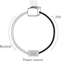
Electricity moves in a circle from power source back to power source, whether it travels across the country in great transmission lines or flows through the cables in your walls. In a house, each distinct electrical loop is called a circuit.

Most of the time, household electricity flows through copper wires (low resistance) insulated with thermoplastic or rubber (very high resist­ance). But electrical current is opportunistic. Should a wire’s insulation break and a fault cir­cuit of lesser resistance become available, current will flow through it. The current flowing through that fault circuit is called a ground fault. The lower the fault circuit’s resistance, the greater that current flow will be.

If equipment and appliances are correctly grounded (bonded together), this abnormally high current flow (amperage) will trip a breaker or blow a fuse, cutting power to the fault circuit—or "clearing the fault,” as electricians say.

ELECTRICITY IN THE HOUSE

A modern electrical system consists of three large cables, or conductors, which may enter the house overhead or underground. When fed underground, service conductors are installed in buried conduit or run as USE (underground service entrance) cable. Overhead service run­ning from a utility pole typically consists of a triplex assembly—two insulated hot conductors wrapped around a bare messenger cable that also serves to carry the neutral load—which runs to a weather head atop a length of rigid

PLAY IT Safe

Only a licensed electrician should work in a service panel—or remove its cover. Even with the main fuse or breaker turned off, some of the cables inside a panel are always hot (carry­ing electricity) and could electrocute you.

So could hot wires touching the sides of an incorrectly wired panel. Don’t mess with electric meters, either: Call the utility company to install meters or upgrade incoming service.

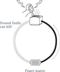
Подпись:Подпись: WIRES, CABLES, AND COPdUCtOrS The terms wires, cables, and conductors are often used interchangeably, but they are not exactly the same. A conductor is anything that carries or conducts electricity. A wire is an individual conductor, and cable is usually an assembly of two or more wires, protected by a plastic or metal cable sheathing (also called a jacket). Often, cable derives its name from the size of the wires within. For example, 12-gauge cable contains 12AWG (American Wire Gauge) wire. More specifically, 12/2 with ground denotes cable with two 12AWG wires plus a ground wire. Подпись: Circuits and Ground Faultsimage463image464Подпись: Electricity tends to move in a circle (circuit) to and from a power source, flowing through insulated wire. Current flowing through an unintended conductor, such as a person, is called a ground fault. Because only a little current flowing through your heart can kill you, ground faults can be fatal.To work safely on existing circuits, always disconnect electrical power at the service panel, and use a voltage tester (see the photos on p. 235) at the outlet to verify that the power’s off. Throughout this chapter (and book), you’ll see this symbol as a reminder:

Подпись: A Service EntranceПодпись: N

AND GROUND FAULTS
Подпись: The main panel houses incoming cables from the meter, as well as the breakers and wires that distribute electricity to individual circuits. At the service, neutral conductors (white wires), equipment-grounding conductors (bare copper or green insulated wires), the metal service panel, and the grounding electrode system (grounding rods) must be bonded together.

conduit. (Overhead service cables are called a service drop.) Whether it arrives overhead or underground, three-wire service delivers 240 volts. An old service with only two incom­ing wires—one hot and one grounded neutral conductor—delivers only 120 volts, which is inadequate for modern household demand and so should be upgraded.

Service conductors attach to a meter base. From the meter base runs another length of rigid conduit, or service entrance (SE) cable, to the service panel. Straddling the two sets of terminals on its base, the meter measures the wattage of electricity as it is consumed. (Increasingly common are meter-main combos, which house a meter base and a main service panel in a single box.)

Main service panel. At the main service panel, the two hot cables from the meter base attach to
lug terminals atop the main breaker, and the incoming neutral cable attaches to the main lug of the neutral/ground bus, as shown in "Main Service Panel, Unwired,” below. In main service panels, neutral/ground buses must be bonded, usually by a main bonding jumper. Important:

In subpanels and all other locations down­stream from the main service panel, ground and neutral buses must be electrically isolated from each other.

In a service fuse box, the hot cables attach to the main power lugs, and the neutral cable to the main neutral lug. Whether the panel has breakers or fuses, metal buses issue from the bottom of the main breaker/main fuse. Running down the middle of the panel, buses distribute power to the various branch circuits. Similarly, neutral/ground buses are long aluminum strips with many screws that ground and neutral wires attach to.

Подпись:image467THE Main BREAKER

All electricity entering a house goes through the main breaker, which is usually located at the top of a main panel. In an emergency, throw the main breaker switch to cut all power to the house.

The main breaker is also the primary overcurrent protection for the electrical system and is rated accordingly. (The rating is stamped on the breaker handle.) Thus if the main breaker for a 200-amp panel senses incoming current that exceeds its overload rating, the breaker will automatically trip and shut off all power.

Each fuse or breaker is rated at a specific num­ber of amperes (amp), such as 15 or 20. When a circuit becomes overloaded, its current flow becomes excessively high, causing its breaker to trip or its fuse strip to melt, thereby cutting volt­age to the hot wires. All current produces heat, but as current doubles, the heat generated quadruples. If there were no breakers or fuses, current would continue flowing till wires overheated and a fire started. Thus the amperage ratings of breakers and fuses are matched to the size (cross-sectional area) of the circuit wires.

Branch circuits. Branch circuits are conductors that run from the last overcurrent device (fuse or breaker) to their outlets. Inside each cable or conduit are several wires color-coded for safety.

In most 120-volt circuits, there is one hot wire (coded black), one neutral wire (coded white), and one bare copper (or green) ground wire. Think of hot and neutral wires as parallel wires that must never be joined.

Ground wires (discussed later in this chapter) must also be kept separate from hot and neutral wires as you run branch circuits. (Ground and neutral bus bars are connected in the main panel, but that’s another issue.) In 240-volt circuits, such as those “dedicated” to a heavy user like a stove, there are typically two hot wires: one coded black, and the other, red.

Outlets. Each branch circuit serves one or more outlets. At outlets, individual wires connect to various devices such as switches, receptacles, and fixtures. To ensure a safe hookup, the devices’ connecting screws or terminals are color coded or otherwise clearly designated: Hot wires attach to gold – or brass-colored screws, neutral wires to silver screws, and ground wires to green screws (when present).

Switches cut or vary the flow of power by inter­rupting hot lines only. Neutral wires are always
continuous, as are ground wires, even though their sections may be connected by wire nuts. Wire nuts are insulated caps that twist onto the bare ends of wire splices (clusters), thereby joining them mechanically and covering them so those bare ends can’t come in contact with other wires, devices, fixture terminals, or the outlet box itself.

THE GROUNDING SYSTEM

A house’s grounding system is complex, and understanding it is made more difficult by the imprecise language used to describe it—as noted in “Making Sense of Grounding,” on p. 230. If you want a more comprehensive overview of grounding, get a copy of the book Code Check® Electrical, mentioned earlier. Here are some of the basics.

Underlying principles. Fuses were among the earliest overcurrent devices, and they greatly reduced the incidence of electrical fires by dis­connecting current when its flow became too great. But something more was needed to protect people, who were being electrocuted when they came in contact with fault currents unintention­ally energizing the metal casing of a tool or an electrical appliance, for example.

Подпись: PROTIP It's advisable to ground metal water piping in case it becomes energized, but don't rely on metal water pipes instead of grounding electrodes. Otherwise, someone could disconnect the pipe or install a section of non-conductive pipe such as PVC, thus interrupting the grounding continuity and jeopardizing your safety. In new installations, code requires that metal water piping be connected to the electrode system and supplemented with another electrode. Подпись: 1111Подпись:Consequently, the industry added equipment­grounding conductors (which we’ll call ground wires) that bond all electrical devices and poten­tially current-carrying metal surfaces. This bond­ing creates a path with such low impedance (resistance) that fault currents zip along it as they return to the power source—quickly tripping breakers or fuses, and clearing the fault. Contrary to popular misconceptions, the human body has a relatively high impedance (compared to copper wire), so if electricity is offered a path of less resistance (a copper ground wire), it will take it.

To sum up: To reduce shock hazards, individ­ual ground wires connect to every part of the electrical system that could become a potential conductor—metal boxes, receptacles, fixtures— and, through three-pronged plugs, the metallic covers and frames of tools and appliances. At the main service panel, these ground wires attach to a neutral/ground bus bar, which is itself bonded to the metal panel via a main bonding jumper.

To quote one master electrician, "This bonding jumper is possibly the most important single con­nection in the whole system.”

Grounding electrode system. Also attached to the neutral/ground bus in the service panel is a large, bare copper ground wire —the grounding electrode conductor (GEC)—that clamps to a grounding electrode (also called a ground rod), which is driven into the earth or is attached to steel rebar in the footing of a foundation. The electrode’s primary function is to divert lightning
and other outside high voltages before they can damage the building’s electrical system.

Note: Although the grounding electrode system (GES) is connected to the equipment­grounding system at the service panel, the GES has virtually nothing to do with reducing shock hazards.

The NEC sizes grounding electrode conduc­tors based on the sizes and types of conductors in the service. Typically, residential GECs are size 6 American Wire Gauge (6AWG) copper. Ground rods are typically 58-in. to 54-in. copper-clad steel rods 8 ft. to 10 ft. long; the longer the rod, the more likely it will reach moist soil, whose resist­ance is less than that of dry soil. Be sure to install multiple-rod systems in lightning-prone areas.

GROUND-FAULT CIRCUIT INTERRUPTERS

Despite the presence of grounding systems, peo­ple were still being killed by electrical shock, particularly when moisture was present. To rem­edy this problem, the industry developed ground-fault circuit interrupters (GFCIs), which are highly sensitive devices that can detect minuscule current leaks and shut off power almost instantaneously. A ground fault is any fail­ure of the electrical system that leaks current from a hot wire.

Normally, the current in hot and neutral wires is identical. But when there is as small a variance as 0.005 amp (5 milliamperes) between hot and neutral wires, a GFCI can shut off all power within 540 of a second. Consequently, the NEC now requires GFCI protection on all bathroom recep­tacles, kitchen receptacles within 4 ft. of a sink, all receptacles serving kitchen counters, all out­door receptacles, accessible basement or garage receptacles, and receptacles near pools, hot tubs, and the like.

A GFCI breaker will cut all power to a circuit, whereas a GFCI receptacle will cut power to receptacles downstream if wires are fed through the GFCI receptacle as shown in "Wiring a GFCI Receptacle,” on p. 250.

ARC-FAULT

CIRCUIT INTERRUPTERS

When electrical connections are loose or corrod­ed or if nails puncture wires, electricity can arc (jump) between points. Arcing may be respon­sible for many of the 40,000 electrical fires each year. The NEC now requires arc-fault circuit interrupter (AFCI) protection for all 15-amp and 20-amp bedroom circuits. Just as GFCIs cut power to prevent shocks, AFCIs detect minute fluctuations in current associated with arcing
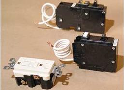
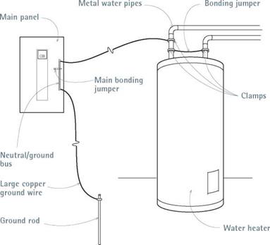
image468image469Подпись: The equipment-grounding system acts as an expressway for stray current. By bonding conductors or potential conductors, the system provides a low-resistance path for fault currents. The abnormally high amperage (current flow) that results trips a breaker or blows a fuse, disconnecting power to the circuit.Electrical safety devices. From fop:arc-fault circuit interrupter (AFCI) breaker, ground-fault circuit interrupter (GFCI) breaker, and GFCI receptacle.

and de-energize the circuits before a fire can start. Installing AFCI breakers is essentially the same as that for GFCI circuit breakers.

Electrical Wiring

Подпись: Use a wire stripper to strip 'h in. of insulation off the wire ends before attaching them to the screw terminals on switches. Begin by scoring the insulation with a twist of the wrist. Then use your thumb as a fulcrum to pop the insulation off.image462

Electrical work is among the most pre­dictable, pleasant aspects of construction—no heavy lumber to be wrestled, no large sheets that would fit if only your fingers weren’t in the way, no quick-drying compounds driving you into a frenzy. Wiring a house is methodical work that requires attention to detail and some dexterity. And you know quickly if you’ve done the work correctly: bulbs glow and radios play.

Electricity should be respected, and it must be taken seriously. But it is a natural phenomenon, subject to the laws of physics. If you heed the safety precautions in this chapter—especially those about shutting off power and testing with a voltage tester, to make sure the power is off— you’ll do fine. If you’re new to wiring, take the time to read the whole chapter because important information is not necessarily repeated.

It’s imperative that you check with local building code authori­ties even before buying tools and materials. Although most building authorities do not for­bid an owner’s doing his or her own electrical work, most require inspections when the system is roughed in—that is, before wires are connected to switches, receptacles, and so on. Besides, building inspectors are usually knowledgeable: They can tell you if local codes con­form to the National Electrical Code® (NEC) or, if not, how they vary.

If this chapter whets your appetite for more, get copies of

Rex Cauldwell’s Wiring a House (The Taunton Press) and Redwood Kardon, Doug Hansen, and Mike Casey’s Code Check® Electrical (The Taunton Press).

Understanding Electricity

Electricity is tricky to describe. A physicist might call it "the movement of electrons,” but most peo­ple find it easier to visualize electricity as some­thing like water flowing through a hose. Using that analogy, here are two useful concepts:

(1) Electrical current flows in a circle, making a circuit, and (2) it flows most easily along paths of least resistance, but it will follow any path that’s available. . . including you!

Damp Basement Solutions

To find the best cure for a damp basement, first determine whether the problem is caused by water outside migrating through foundation walls or by interior water vapor inside condens­ing on the walls. To determine which problem you have, duct tape a 2-ft.-long piece of alu­minum foil to the foundation, sealing the foil on all four sides. Remove the tape after 2 days. The wet side of the foil will provide your answer. Chapter 14 has more about mitigating moisture and mold.

CORRECTING CONDENSATION

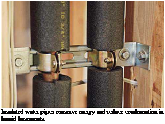
If the problem is condensation, start by insulating cold-water pipes, air-conditioning ducts, and other cool surfaces on which water vapor might con­dense. Wrap pipes with preformed foam pipe insu­lation. Wrap ducts and larger objects with sheets of vinyl-faced fiberglass insulation, which is well suited to the task because vinyl is a vapor barrier. Use duct tape or insulation tape to seal seams.

Next install a dehumidifier to remove excess humidity. For best results, install a model that can run continuously during periods of peak humidi­ty; place it in the dampest part of the basement at least 12 in. away from walls or obstructions. To prevent mold from growing in the unit’s collection reservoir, drain it daily and scrub it periodically.

Survey the basement for other sources of humidity. An unvented clothes dryer pumps gal­lons of water into living spaces; vent it outdoors. Excessive moisture from undervented kitchens and bathrooms on other floors can also migrate to the basement; add exhaust fans to vent them properly. Finally, weatherstrip exterior doors and keep them closed in hot, humid weather.

DAMPNESS DUE TO EXTERIOR WATER

Position and maintain gutters and downspouts so they direct water away from the house. And, if possible near affected walls, slope soil away from the house.

Besides those two factors, water that migrates through foundation walls or floors is more elu­sive and expensive to correct. Basically, you have three remedial options: (1) remove water once it gets in; (2) fill interior cracks, seal interior sur­faces, and install a vapor barrier; and (3) exca­vate foundation walls, apply waterproofing and improve drainage.

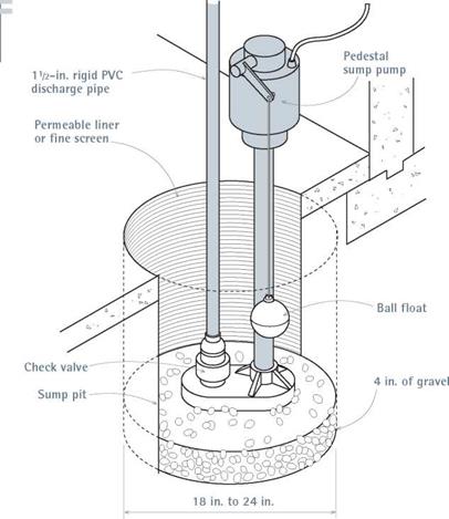
Option one: Remove water. Sump pumps are the best means of removing water once it gets
into a basement. If you don’t have a sump pump, you’ll probably need to break through the base­ment floor at a low point where water collects, and dig a sump pit 18 in. to 24 in. across. Line the pit with a permeable liner that allows water to seep in while keeping soil out, and put 4 in. of gravel in the bottom.

There are two types of sump pumps. Pedestal sump pumps stand upright in the pit. They are water cooled and have ball floats that turn the pump on and off. Submersible sump pumps, on the other hand, have sealed, oil-cooled motors, so they tend to be quieter, more durable, and more expensive. And because they are submerged, they allow you to cover the pit so nothing falls in. A й-hp pump of either type should suffice.

The type of discharge pipe depends on whether the pump is a permanent fixture or a sometime thing. Permanent pumps should have 112-in. rigid PVC discharge pipes with a check valve near the bottom to prevent expelled water from siphoning back down into the pit. If the water problem is seasonal, many people simply attach a 50-ft. gar­den hose and run it out a basement window. In either case, discharge the water at least 20 ft. from the house, preferably downhill and not directly into a neighbor’s property.

Option two: Interior solutions. If basement walls are damp, try filling cracks as suggested on p. 205 and applying damp-proofing coatings. (However, this approach won’t work if the walls are periodically wet. After scrubbing the base­ment walls, parge (trowel on) a cementitious coating such as Thoroseal® Foundation Coating or Sto Watertight Coat® or a polymer-modified system such as Bonsal’s Surewall®. These coat­ings can withstand higher hydrostatic pressures than elastomeric paints or gels. Epoxy-based coatings also adhere well but are so expensive that they’re usually reserved for problem areas such as wall to floor joints.

To further control moisture diffusion through the walls, install a vapor barrier. After parging the walls with a damp-proofing material, use con­struction adhesive to attach heavy (6-mil at a minimum) sheet polyethylene to the foundation walls. Then place sheets of rigid foam insulation over the plastic sheeting. Caulk and tape the foam seams to seal them. If the seams are airtight, the insulation layer becomes a second vapor barrier and makes condensation less likely because it iso­lates cool basement walls from warm air.

Option three: Exterior solutions. To water­proof exterior foundation walls, first excavate them. At that time, you should also upgrade the perimeter drains, as shown in "Foundation Drainage,” on p. 203. Then, after backfilling the excavation, slope the soil away from the house. That is, no waterproofing material will succeed if water stands against the foundation. Before applying waterproofing membranes, scrub the foundation walls clean and rinse them well.

► Liquid membranes are usually sprayed on, to a uniform thickness specified by the manufacturer, usually 40 mil. That takes train­ing, so hire a manufacturer-certified installer. Liquid membranes are either solvent based or water based. Modified asphalt is one popular solvent-based membrane that contains rubber­like additives to make it more flexible and durable. Asphalt emulsions are water based and widely used because, unlike modified asphalt, they don’t smell strong, aren’t flammable, and won’t degrade rigid foam insulation panels placed along foundation walls. Synthetic – rubber and polymer-based membranes are also water based; they’re popular because their inherent elasticity allows them to stay flexible and span small cracks. Note: Water-based membranes dry more slowly than solvent-based ones and can wash off if rained on before they are cured and backfilled.

► Peel-and-stick membranes are typically sheet or roll materials of rubberized asphalt fused to polyethylene. They adhere best on pre­primed walls. To install these membranes, peel off the release sheet and press the sticky side of the material to foundations. Roll the seams to make them adhere better. Peel-and-stick costs more and takes longer to install than sprayed – on membranes, but they’re thicker (60 mil, on average) and more durable. Though not widely used on residences, these materials seem justified on sites with chronic water problems. They’re often called Bituthene®, after a popular W. R. Grace Construction product.

► Air-gap membranes aren’t true mem­branes because they don’t conform to the surface of the foundation. Rather, they are
rigid plastic (polyethylene) sheets held out from the foundation by an array of tiny dim­ples, which creates an air-drainage gap. Water that gets behind the sheets condenses on the dimples and drips free, down to foundation drains. (For this system to work, you must coat the foundation walls first.) Air-gap sheets are attached with molding strips, clips, and nails; caulk the sheet seams.

► Until technology transformed water­proofing compounds, cementitious coatings rivaled unmodified asphalt as the most com­mon stuff smeared onto foundations. These days, acrylic additives make cement-based coatings a bit more flexible, but they will still crack if the foundation flexes. Bentonite, a vol­canic clay sheathed in cardboard panels, swells 10 times to 15 times its original volume when wet, keeping water away from foundation walls. Use construction adhesive or nails to attach the panels. These panels are costly and not widely available, and they can be ruined if rained on before the foundation is backfilled.

Подпись: PROTIP Waterproofing membranes are relatively fragile, especially those that are sprayed on. So after they're applied, they're often covered with rigid insulation, drain board, protection board, and the like. These rigid panels protect the membranes during backfilling, and insulate the foundation walls to reduce heat loss. Подпись: 1111image460I Pedestal Sump Pump

Cubic Yards of Concrete in Slabs of Various Thicknesses* t

/

Подпись: ^^^AREA (sq. ft.) 1.0 in. 1.5 in. 2.0 in. 2.5 in 3.0 in. 3.5in. 4.0 in. 4.5 in. 5.0 in. 5.5 in. 6.0 in 10 0.03 0.05 0.06 0.08 0.09 0.11 0.13 0.14 0.15 0.17 0.19 20 0.06 0.09 0.12 0.16 0.19 0.22 0.25 0.28 0.31 0.34 0.37 30 0.09 0.14 0.19 0.23 0.28 0.33 0.37 0.42 0.46 0.51 0.56 40 0.12 0.19 0.25 0.31 0.37 0.43 0.50 0.56 0.62 0.68 0.74 50 0.15 0.23 0.31 0.39 0.46 0.54 0.62 0.70 0.77 0.85 0.93 60 0.19 0.28 0.37 0.46 0.56 0.65 0.74 0.83 0.93 1.02 1.11 70 0.22 0.32 0.43 0.54 0.65 0.76 0.87 0.97 1.08 1.19 1.30 80 0.25 0.37 0.49 0.62 0.74 0.87 1.00 1.11 1.24 1.36 1.48 90 0.28 0.42 0.56 0.70 0.84 0.97 1.11 1.25 1.39 1.53 1.67 100 0.31 0.46 0.62 0.78 0.93 1.08 1.24 1.39 1.55 1.70 1.85 200 0.62 0.93 1.23 1.54 1.85 2.16 2.47 2.78 3.09 3.40 3.70 300 0.93 1.39 1.85 2.32 2.78 3.24 3.70 4.17 4.63 5.10 5.56 400 1.23 1.83 2.47 3.10 3.70 4.32 4.94 5.56 6.17 6.79 7.41 500 1.54 2.32 3.09 3.86 4.63 5.40 6.17 7.00 7.72 8.49 9.26 600 1.85 2.78 3.70 4.63 5.56 6.48 7.41 8.33 9.26 10.19 11.11 700 2.16 3.24 4.32 5.40 6.48 7.56 8.64 9.72 10.80 11.88 12.96 800 2.47 3.70 4.94 6.20 7.41 8.64 9.88 11.11 12.35 13.58 14.82 900 2.78 4.17 5.56 6.95 8.33 9.72 11.11 12.50 13.89 15.28 16.67 1,000 3.09 4.63 6.17 7.72 9.26 10.80 12.35 13.89 15.43 16.98 18.52
Подпись: This table can be used to estimate the cubic content of slabs larger than those shown. To find the cubic content of a slab measuring 1,000 sq. ft. and 8 in. thick, add the figures given for thicknesses of 6 in. and 2 in. for 1,000 sq. ft. f Courtesy of Bon Tool Company, © 2003, from Statistical Booklet: Contractors, Tradesmen, Apprentices (see also www.bontool.com).

slabs consist of 4 in. of concrete poured over 4 in. of crushed rock, with a plastic moisture barrier between. In addition, garage floors are often reinforced with steel mesh or rebar to support greater loads and forestall cracking.

PREP STEPS

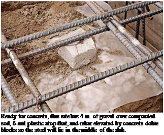
As with any concrete work, get plenty of help. Concrete weighs about 2 tons per cubic yard, so if your slab requires 10 cu. yd., you’ll need to move and smooth 40,000 lb. of concrete before it sets into a monolithic mass. Time is of the essence, so make sure all the prep work is done before the truck arrives: Tamp the crushed stone, spread the plastic barrier (minimum of 6 mil), and elevate the steel reinforcement (if any) on
dobie blocks or wire high chairs so it will ride in the middle of the poured slab. Finally, snap level chalklines on the basement walls or concrete forms to indicate the final height of the slab— you’ll screed to that level.

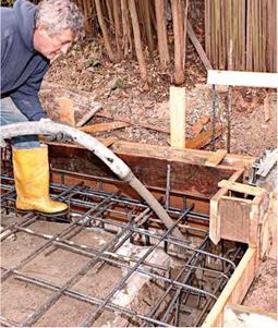
To pour concrete with a minimum of wasted energy, use a 2-in. (interior diameter) concrete – pump hose. A hose of that diameter is much lighter to move around than a 3-in. hose. Another advantage: It disgorges less concrete at a time, allowing you to control the thickness of the pour better. And a 2-in. hose gives easier access to distant or confined locations. Important: As you place concrete around the perimeter of the slab, be careful not to cover up the chalklines you snapped to mark the slab height. And as you

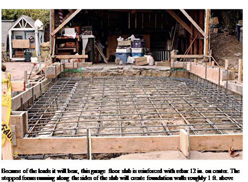
Подпись: Ordering Concrete: Be Specific Concrete has so many different uses (such as floors, foundations, and countertops) and so many admixtures (water reducers, retardants, accelerants, air entrainers, and so on) that the best way to get the mix you need is to specify its use and desired characteristics. That is, when ordering the mix, tell the supplier the quantity you need (in cubic yards), how the concrete will be used (driveway, foundation, patio slab), the loads it will bear, how far it must be pumped, how it will be finished, and other such details. If you're pouring a slab that will have a smooth finish, you might specify "a 2,500 psi mix, but a true five-sack mix," which will be "creamy" enough to finish with a steel trowel. If you specify a 2,500 psi mix but don't describe the finish, the supplier might use four sacks of cement and a water reducer to attain that strength. However, with less cement in it, the mix would be sandier and more difficult to finish. Where the concrete will be placed can also affect the mix. For example, concrete for a second-story patio far from the street may require a smaller, 2-in. (inner diameter) hose to pump it, so the supplier may specify smaller aggregate (3/s-in. vs. 3/4-in.) to facilitate flow. Aggregate size, in turn, affects load-bearing capacity, so a mix with 3/s-in. gravel is often bumped up, say, to 3,000 psi. If the patio slab will also be steel troweled, the mix thus becomes "a 3,000 psi, 3/s-in. aggregate, true six-sack mix." Well, you get the point: Be specific. Estimating the amount of concrete in cubic yards is straightforward: The calcula-tion is width x length x depth (in feet) of the area you want to cover. You then divide that result by 27 (as there are 27 cu. ft. in 1 cu. yd.). If you're pouring a slab, "Cubic Yards of Concrete in Slabs of Various Thicknesses," on p. 221, calculates cubic yards based on the slab thickness (in inches). Most concrete-mixer trucks can hold 9 cu. yd. to 11 cu. yd. So if your pour requires more than one truck, ask the supplier to time deliveries 90 minutes apart so you have enough time to deal with each delivery. Finally, don't shave the estimate too close; far better to have too much concrete than too little. Подпись: Because of the loads it will bear, this garage floor slab is reinforced with rebar 12 in. on center. The stepped forms running along the sides of the slab will create foundation walls roughly 1 ft. above grade. place concrete in the slab footings, drive out the air pockets by using a concrete vibrator.
Establishing screed levels. If the slab is only 10 ft. or 12 ft. wide, you can level the concrete by pulling a screed rail across the top of form boards. Otherwise, create wet screeds (leveled columns of wet concrete) around the perimeter of the slab and one in the middle of the slab to guide the screed rails. The wet screeds around the perimeter are the same height as the chalk­lines; pump concrete near those lines and level it with a trowel. This technique is very much like that used to level tile mortar beds, as explained in Chapter 16.

The wet screed(s) in the middle should be more or less parallel to the long dimension of the slab. There are several ways to establish its height, but the quickest way is to drive 18-in. lengths of rebar into the ground every 6 ft. or so, and then use a laser level or taut strings out from perime­ter chalklines to establish the height of the rebar. In other words, the top of the rebar becomes the top of the middle wet screed. When you’ve troweled that wet screed level, hammer the rebar below the surface, and fill the holes later.

SCREEDING AND FLOATING

Screeding is usually a three-person operation: two to move the screed rail back and forth, strik­ing off the excess concrete, and a third person behind them, constantly in motion, using a stiff rake or a square-nose shovel to scrape down high spots or to add concrete to low ones. You can use a magnesium screed rail or a straight 2×4 to strike off, but the key to success is the raker’s maintaining a good level of concrete behind the screeders, so the screed rail can just skim the crest of the concrete, without getting hung up or bowed by trying to move too much material.

Screeding levels the concrete but leaves a fairly rough surface, which is then smoothed out with a magnesium bull float, a long-handled float that also brings up the concrete’s cream (a watery cement paste) and pushes down any gravel that’s near the surface. This creates a smooth, stone-free surface that can be troweled and compacted later.

A bull float should float lightly on the surface. As you push it across the concrete, lower the han­dle, thereby raising the far edge of the float. Then, as you pull the float back toward you, raise the handle, raising the near edge. In this manner, the leading edge of the bull float will glide and not dig into the wet concrete.

Подпись: Fill slab footings first; then vibrate them to drive out any air pockets. Because placing a concrete slab usually entails standing in it, wear rubber boots.
image454
Подпись: Ready for concrete, this site has 4 in. of gravel over compacted soil, 6-mil plastic atop that, and rebar elevated by concrete dobie blocks so the steel will lie in the middle of the slab.

FINISHING THE SLAB

After the bull float raises water to the surface, you must wait for the water to evaporate before finishing the concrete. The wait depends on the weather. On a hot, sunny day, you may need to wait less than an hour. On a cool and overcast day, you might need to wait for hours. Once the water’s evaporated, you have roughly 1 hour to trowel and compact the surface. When you think the surface is firm enough, put a test knee board atop the concrete and stand on it. If the board sinks % in. or more, wait a bit. If the board leaves only a slight indent that you can easily hand float further and then trowel smooth, get to work.

As the photos show, knee boards distribute your weight and provide a mobile station from which to work. You’ll need two knee boards in order to move across the surface, moving one board at a time. Then, kneeling on both boards, begin sweeping with a magnesium hand float or with a wood float, if you prefer a rougher finish. Sweep back and forth in 3-ft. arcs, raising the far edge of the float slightly as you sweep away and raising the near edge on the return sweep. The “mag” float levels the concrete.

After you’ve worked the whole slab, it’s time for the steel trowel, which smooths and compacts the concrete, creating a hard, durable finish.

As the concrete dries, it becomes harder to work, so it’s acceptable to sprinkle very small amounts of water on the surface to keep it work­able. Troweling is hard work, especially on the back. When the concrete’s no longer responding to the steel trowel, edge the corners and then cover the concrete with damp burlap before call­ing it a day. If the weather’s hot and dry, hose down the burlap periodically—every hour, at

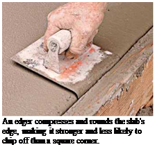
Подпись: Finishing the slab. Start with magnesium or wood floats, and finish with a steel trowel for a smooth, hard finish. Knee boards distribute your weight as you work. Подпись: An edger compresses and rounds the slab's edge, making it stronger and less likely to chip off than a square corner. Подпись: Insulated water pipes conserve energy and reduce condensation in humid basements. least—and keep the slab under cover for 4 or 5 days. At the end of that time, you can remove the forms. Concrete takes a month to cure fully.

Capping a Foundation

Capping an old foundation with new con­crete is relatively rare but is done when the existing foundation is in good condition and needs to be raised because the house’s framing is too close to the ground, allowing surface water to rot sills and siding.

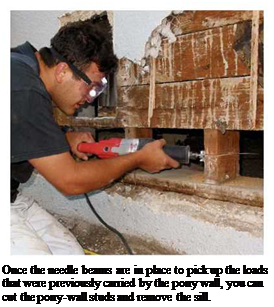
To raise wood members sufficiently, the new cap must be 8 in. above grade. At the very least, that means shoring up the structure, removing the existing mudsill, shortening the pony-wall studs, drilling the old foundation, epoxying in rebar pins to tie the new concrete to the old, and pouring new concrete atop or around some part of the existing foundation. That’s a lot of work. So if the existing founda­tion is crumbling or lacks steel reinforcement, you should replace it altogether.

On the other hand, if the house lacks pony walls and the joists rest directly on the founda­tion, you have basically two options: (1) grade the soil away from the house to gain the neces­sary height, which may not be possible if the foundation is shallow, or (2) jack up the house at least 8 in., which means hiring a house mover. Here again, replacing the foundation is usually more cost effective.

Otherwise, cut the tops of the stakes off and leave the rest embedded in the new concrete.

Hammer the outside of the form boards and then use a concrete vibrator, to drive out the air pockets. For this, insert the hose-like vibrator into the forms. As the concrete approaches the tops of forms, signal the pump to shut off so that the concrete doesn’t spill over the sides. When the forms are full and vibrated, use a trowel to flatten the top of the wall and sponge off any globs on the stakes and forms. Allow the concrete to cure 3 days at a minimum and 7 days for the optimum, before removing the forms and shoring, replacing the siding, and tightening down the washered anchor bolts. For further pro­tection against moisture, apply below-grade waterproofing to the outside wall and footing before backfilling.

Concrete Work

Concrete is a mixture of portland cement, water, and aggregate (sand and gravel). When water is added to cement, a chemical reaction, called hydration, takes place, and the mixture hardens around the aggregate, binding it fast. Water makes concrete workable, and cement makes it strong. The lower the water to cement ratio (w/c), the stronger the concrete.

POURING A CONCRETE SLAB

Pouring (or placing) a concrete slab is pretty much the same procedure, whether for patios, driveways, basements, or garage floors. Most

ATTACHING THE MUDSILL

Builders may attach new mudsills at different stages of form assembly. But here are the essen­tials. Before nailing up the mudsill (to the bot­tom of the pony-wall studs) predrill for anchor bolts, as described earlier, making sure that no bolt occurs under a stud. If local codes require metal termite shields, tack them to the under­side of the mudsill after first predrilling it with anchor-bolt holes. Then, using a pneumatic nailer, end-nail the sill to the studs, using two 16d nails per stud. If there isn’t enough room to end-nail upward into the sill, jack the mudsill tight to the studs and toenail down from the studs into the mudsill.

Once the mudsill is nailed to the studs, insert anchor bolts into the predrilled holes, screw on washers and nuts, and tie the free ends of the bolts to the rebar. At this point, the nuts should be just snug; you can tighten them down after the concrete has cured. If you end – nailed the mudsill, make sure the studs are tight to the top plates above: Jack up any studs that have separated. You may also need to brace the pony wall if it’s loose, which is often the case if you have to demolish siding to remove it. Pony walls should be plumb and aligned with the forms.

POURING CONCRETE

After installing the outside form boards, you are almost ready to pour. If you are using a 2-in. hose (interior diameter) to pump the concrete to the site, make sure there is at least a 3-in. clearance between the edge of the form board and the out­side edge of the new mudsill, to accommodate the width of the pump nozzle. If necessary, notch the forms so the nozzle can fit. The top of the form should be slightly higher than the bottom of the mudsill.

Fill the footing to the bottom of the wall forms before filling the forms. Some concrete may slop over from the walls onto the footing and bottom form boards, but slopover isn’t a problem if you remove the concrete from the form bottoms before it sets up. That will allow easy removal of the forms once the concrete has cured.

When the concrete begins to set, but is not completely hard, pull out the perforated steel stakes holding the bottom form boards in place. To do this, remove the duplex nails and then use either a pipe wrench to grip the stakes or a commercial stake puller. If you leave the stakes in till the next day, you’ll likely be able to pull them only if you remembered to oil them first.

Подпись: If I У . Vу 4.’-1 t.t Кв л ll Wi/fYw-r ШжТш image451This 2-in. (interior diameter) concrete-pump hose is easier to handle than a 3-in. hose. But its smaller diameter requires smaller, 7o-in. aggregate in the mix. Although a 2-in. hose is much lighter than a 3-in., tons of concrete pass through it—so you’ll need helpers to support the hose and move it to the pouring points.
Подпись: PROnP If you have a septic tank, show the driver of the concretemixer truck where the tank and fields lie, so he or she doesn't drive over and crush them. After the pour, make sure the driver doesn't rinse and empty the truck's residue on your yard. You may want to plant a lawn there someday. ■ ill

REMOVING OLD FOUNDATIONS

To tear out an old foundation, you’ve got several options. All require safety glasses, hearing protec­tion, heavy gloves, a mask, patience, and a strong back. Before acquiring heavy and expensive equipment, try to break out a section of the old foundation using a 9-lb. sledgehammer and a 6-ft. pointed steel bar. Old concrete without rebar is often cracked and soft. Once you’ve removed a small section, the rest may come out easily.

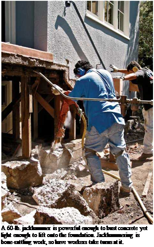
If the concrete is too thick and hard, rent a towable air compressor and jackhammer. A 90-lb. jackhammer will break almost anything, but it’s a beast to maneuver; a 60-lb. hammer is light enough to lift onto a foundation wall and almost always strong enough to break a wall apart. A 60-lb. electric jackhammer is less powerful than a compressor-driven one, but it may have enough muscle to get the job done.

Or you can rent a gas-powered saw with a 10-in. concrete-cutting blade that cuts 4 in. to 5 in. deep, letting you cut the concrete into man­ageable chunks. A third option is rotohammering a line of 58-in. holes across the foundation and then splitting along that line with a large mason’s chisel and a hand sledge.

Should you encounter rebar, you’ll either need an acetylene torch to cut through it or a metal abrasive wheel in a circular saw or grinder. Rebar cutting is monstrously hard work. With the old foundation removed, you can excavate new foot­ings from outside the house and install forms for the concrete.

Подпись:Подпись: A 60-lb. jackhammer is powerful enough to bust concrete yet light enough to lift onto the foundation. Jackhammering is bone-rattling work, so have workers take turns at it. Подпись: POSITIONING Foundation FACES Подпись: Traditionally, the outside face of a foundation wall is flush to the edge of the house framing, allowing sheathing to overhang the foundation 1 in. or so, covering the joint between foundation and framing. However, contractors who install a lot of stucco argue that a foundation face flush to the outer face of the sheathing better protects the sheathing edge and creates a stucco edge that's less bulky—that is, one that sticks out less beyond the foundation wall. Whichever detail you prefer, drop a plumb bob to establish the foundation's outside face. If the foundation wall is 8 in. thick, measure back 8 in. from the plumb line to mark the foundation's inside face.

CONCRETE FORMWORK

Correctly positioning 1 ^-in.-thick form boards can be tricky, and there are myriad ways to do so. Here’s a relatively foolproof method, in which you first erect the inner (house side) form walls, by nailing them to 2×4 form-hangers nailed to joists. This method also enables easy access for tying rebar, reattaching sills, and the like.

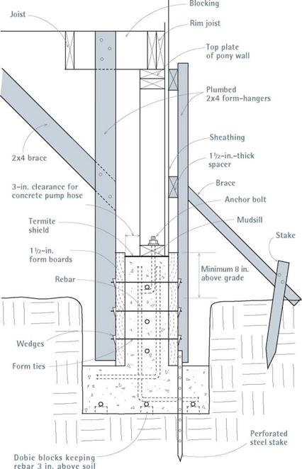
Inner form walls. If floor joists run perpendicu­lar to the foundation wall, start by nailing 2×4 form-hangers into the joists at both ends of the foundation wall section being replaced. The 2x4s should extend down into the foundation trench, stopping 1 in. or 2 in. above the tops of footing forms, if any. Position each 2×4 so its edge is exactly 9/2 in. from the outside face of the foun­dation (8-in.-thick concrete plus "2-in.-thick form board). First nail the bottom form board to the 2x4s; then add 2×4 form-hangers between the first two. Spacing 2×4 form-hangers every 32 in., use two 16d nails to nail them to each joist. Then stack additional form boards atop the first until the top board is slightly above the bottom of the mudsill. As shown in "Concrete Forms for a Shallow Foundation,” on p. 217, run diagonal 2×4 braces from joists to the 2×4 form-hangers to stiffen the inner form wall, thereby keeping it plumb and in place (see also the photos on p. 200 and on p. 216, left).

If the joists instead run parallel to the founda­tion, first add blocking between the rim joist and the first joist back, across the top of the pony wall. Nail the 2×4 form supports to the blocking, much as just described for perpendicular joists. Once the inside forms are complete, you can cut, bend, and assemble the rebar; attach the mudsill
to the pony-wall studs; and insert anchor bolts before build­ing the outside form walls. Even if local building codes don’t require steel-reinforced founda­tions, adding steel is money well spent (see "Adding Steel,” on p. 217).

Outer form walls. If your foun­dation is shallow and the sides of its trenches are cleanly cut, you may not need form boards for footings. But if your footings will have form boards, install them before building the foun­dation’s outer form walls.

If there are no footing form boards, drive 4-ft.-long perfor­ated steel stakes down into the footing area to secure the bot­tom form boards for the outer form walls. Plumb and space these stakes out 1 ‘h in. from the outside face of the foundation, to allow for the thickness of the form boards. Use two stakes per form board to get started.

Use 8d duplex nails to attach form boards to the steel stakes.

Install this first outer form board a little higher than the inner form board initially; then hammer the stakes down to achieve level. Note: You may need several tries to drive stakes that are plumb and accurately positioned because, during driv­ing, stake points are often deflected by rocks. Use a magnetic level to plumb the stakes.

Once the steel stakes are correctly posi­tioned and the bottom form boards are nailed to them, add 2×4 form-hangers so you can hang additional form boards above. But first, nail spacers to the pony-wall studs, to compen­sate for the thickness of the U2-in.-thick form boards. If the pony-wall studs are sheathed,

Подпись: Use prelooped wire ties to splice lengths of rebar, overlapping rebar sections at least 12 in. Note the cleanly cut sides of this trench, which will serve as forms for the poured foundation footings. An electric demolition hammer with a shovel bit was used to cut this dense soil. nail 1 й-in.-thick spacer boards to the studs, so the back face of the form boards lines up with the exterior sheathing. If the studs aren’t presently sheathed, nail up 2-in.-thick spacers to accommodate the thickness of the form boards and the sheathing to come. If the outer face of the foundation wall aligns to the face of the sheathing, you can easily cover that often- troublesome joint with siding.
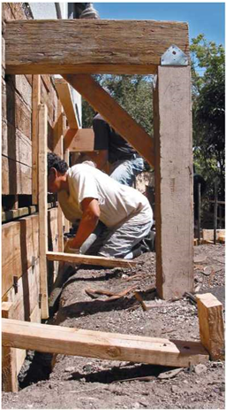
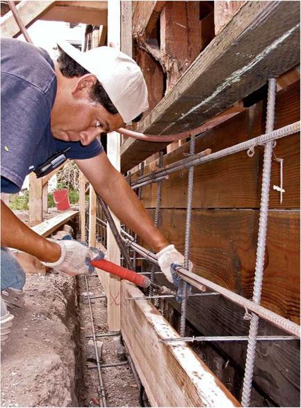
As you install each form board atop the pre­ceding one, set the form ties that tie together inner and outer form boards. Form ties are designed to space the form boards exactly the right distance apart; they are available in 6-in., 8-in., 10-in., and 12-in. lengths. Use wire to tie the form ties to each vertical rebar, typically spaced 32 in. on center. At the ends of each form tie, insert metal wedges into the slots to keep
forms from spreading when filled with concrete. The top form board should overlap the mudsill slightly.

The outer form boards are braced by the plumbed 2×4 form-hangers, which are in turn supported by diagonal braces running back down to perforated steel stakes or to 2×4 stakes driven into the ground. Under the house, diagonal braces run from the inner form-hangers to the joists.

image443
image442

Note: After the pour, you’ll be able to remove form boards and steel stakes if you first sprayed them with form-release oil. But be careful not to spill the oil onto the rebar, anchor bolts, or old foundation, because the oil will weaken the bond with new concrete.

Подпись: To use this rebar cutter-bender, you feed rebar parallel with the base arm for bending, as shown, and perpendicular to the base arm when cutting.
image444
Подпись: In this example, foundation walls are flush to the sheathing, and the trench walls serve as forms for the footings. Details will vary slightly, depending on the direction of joist, (as described in the text) and on other framing particulars.

image445

Structural steel used in renovated foundations includes rebar, anchor bolts, to attach framing to concrete; pins (or dowels), which tie old founda­tions to new ones; and a plethora of metal connec­tors, including the popular Simpson Strong-Ties), which strengthen joints against earthquakes, high winds, and other racking forces.

Rebar. Rebar in foundations is not specified by all building codes, but it’s cost-effective insurance against cracking caused by lateral pressures of soil and water against foundations. Rebar can also eliminate concrete shrinkage cracks. Common sizes in residential construction are No. 3 (58 in. in diameter), No. 4 (52 in.), and No. 5 (58 in.). One common configuration is No. 4 rebar spaced every 32 in. or 48 in. on center.

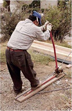
In footings and foundation walls below grade, place rebar back 3 in. from forms and at least 3 in. above the soil. On the inner side of the foun­dation walls, rebar can be within 152 in. of the forms. You should run rebar the length of a foun­dation, tying the lengths together after overlapping them at least 12 in. Use prelooped wire ties to join them. (Wire ties don’t lend strength; they simply hold the bars in place before and during the pour.) Use wire ties to attach rebar to the anchor bolts, pins, form ties, and the like. Use a cutter-bender to cut and bend bars on small jobs. When rebar is delivered, store it above the ground—dirty rebar doesn’t bond as well.

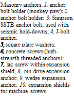
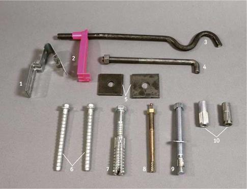
Подпись: Masonry anchors. 1, anchor bolt holder (monkey paw); 2, anchor bolt holder; 3, Simpson SSTB anchor bolt, used with seismic hold-downs; 4, J-bolt anchor; 5, square plate washers; 6, concrete screws (high- strength threaded anchors); 7, lag screw within expansion shield; 8, pin-drive expansion anchor; 9, wedge expansion anchor; 10, expansion shields for machine screws. Подпись: PROnP If you're retrofitting anchor bolts to existing mudsills, begin with a wood-cutting bit to drill through the sill. Then switch to a rotary hammer bit to drill into the concrete foundation. Because the tip of the wood bit invariably hits concrete as it clears wood, you'll ruin the bit before long. But rotary hammer bits are too slow and ineffective at cutting wood. llll image446Anchor bolts. Place й-in. or й-in. anchor bolts no more than 6 ft. apart in one-story house foun­dations and no more than 4 ft. apart in two-story foundations. In earthquake zones, 4-ft. spacing is acceptable, but conscientious contractors space the bolts every 3 ft. There should also be an anchor bolt no farther than 1 ft. from each end of the sills. For maximum grip, use square washers. When pouring a new foundation, use J-type anchor bolts; the plastic bolt holders shown in the photo on p. 202 will position the anchor bolts in the middle of the foundation wall.
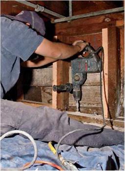
When retrofitting bolts to existing founda­tions, use 58-in. all-thread rod cut to length. Rod lengths will vary according to code specs and sill thickness. For example, a 10-in. rod will accom­modate a washer, nut, and l-in.-thick mudsill and will embed 7 in. in the concrete. You can also buy precut lengths of threaded rod, called retrofit bolts, which come with washers and nuts. Drill through the mudsill into the concrete, clean out the holes well, inject epoxy, and then insert the rods and bolts. The procedure is essentially the same for epoxying rebar pins to tie new concrete to old.

Because bolts, all-thread rods, and other tie-ins are only as strong as the material around them, you should center bolt holes in the top of the old foundation and drill them 6 in. to 8 in. deep, or whatever depth local codes require. Use an impact drill if you’re drilling concrete. Drill
holes 58 in. larger than the diameter of the bolt so there’s room for epoxy. For example, for 58-in. all-thread rod, drill 54-in. holes; for 58-in. rod, drill 58-in. holes. Even if you oversize such holes, the bond probably won’t be weaker, but you may waste a lot of expensive epoxy.

Note: To anchor mudsills in retrofits, threaded rod and epoxy have largely replaced expansion bolts. These chemical bonds are almost always stronger than mechanical ones, and epoxy’s com­pressive strength is roughly four times greater than that of concrete.

Pins. Concrete cold joints are inherently weak. Cold joints occur when new concrete is butted against old or when separate pours create seams. To keep cold joints from separating, you need to join them with rebar pins. When drilling lateral holes to receive rebar pins that tie old walls to new (or secure a foundation cap), angle the drill bit slightly downward, so the adhesive you’ll inject into the hole won’t run out and so pins will be less likely to pull out.

Local codes and structural engineers will have the final say on sizing and spacing rebar pins. But, in general, drill 5й-іп. holes for й-in. rebar to be epoxied; drill holes at least every 58 in. and embed rebar at least 7 in. into the top of founda­tions, and at least 4 in. into the side of 8-in.-thick walls. Extend rebar epoxied into the old founda­tion at least 18 in. into new formwork, and over­lap rebar splices at least 58 in.

image447

Retrofitting anchor bolts requires drilling in tight spaces. Bolts should be centered in the sill and embedded at least 7 in. into the concrete.