Posted by admin on 13/ 11/ 15
Rolling offsets can be figured with a complex method or with a simplified method. since i assume that you are interested in the most accurate information that you can get in the shortest amount of time, i will give you the simplified version. The results will be the same as the more complicated method, but you will not pull out as much hair or lose as much time as you would with the other exercise, and you will arrive at the same solution.
|
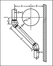
FIGURE 2.8 ■ Starting point of a 451 offset around a tank.
|
|
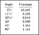
FIGURE 2.9 ■ Simplified method of figuring a rolling offset.
|
To figure rolling offsets simply, you will need a framing square, just a typical, steel, framing square. The corner of any flat surface is also needed, so that you can form a right angle. You will also need a simple ruler. The last tool needed is the table that I am providing in Fig. 2.9. This is going to be really easy, so don’t run away. Let me explain how you will use these simple elements to figure rolling offsets.
stand your framing square up on a flat surface. The long edge should be vertical and the short edge should be horizontal. The long, vertical section will be the Set, and the short, horizontal section will be the Roll. Your ruler will be used to tie the Set together with the Roll (Fig. 2.10 square and ruler). A constant will be needed to arrive at a solution, and you will find constants in the table I’ve provided in Fig. 2.9. Once again, the three main angles are addressed.
|
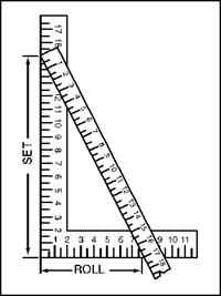
FIGURE 2.10 ■ Laying out a rolling offset with a steel square.
|
When you refer to Fig. 2.9, you will find that the constant for a 45° bend is 1.414. The number for a 60° bend is 1.154, and the constant for a 22V2- bend is 2.613. If you were working with a 45° angle that had a Set of 15 inches and a Roll of eight inches, you would use your ruler to measure the distances between the two marks on the framing square. In this case, the measurement from the ruler would be 17 inches. You would multiply the 17-inch number by the 45° constant of 1.414 (found in Fig. 2.10) and arrive at a figure of 24V32 of an inch. This would be the length of the pipe, from center to center, needed to make your rolling offset. Could it get any easier?
Posted by admin on 13/ 11/ 15
You’ve just seen how to get around what many would see as a typical problem. Most offsets are used to get around square or rectangular objects. But, what happens when you have to bypass a round object, such as a pressure tank? Don’t worry, there is a simple way to get around most any problem, so let’s talk about going around circular objects.
Okay, we have a pipe that has to rise vertically, but there is a horizontal expansion tank hanging in the ceiling that is blocking the path of our pipe. We have a very limited amount of space on either side of the tank to work
within, so our measurements have to be precise. Assume that an eyeball measurement will not work in this case. So, let’s set up the symbols that we will use in this formula.
Let’s use the letter A to indicate the center of the offset rising pipe from the center of the expansion tank. The letter B will represent the center of the offset rising pipe from the edge of the tank. One-half of the diameter of the tank will be identified by the letter C. We will use the letter D to indicate the distance from the center line of the tank to the starting point of the offset. Additional information needed is that A = B + C and D = A X.4142. See Fig. 2.8 for a drawing to help you visualize the setup.
To put the letters into numbers, let’s plug in some hypothetical numbers. Assign a number of 18 inches to C and eight inches to B. What is D? Here’s how it works. A = B + C = 8 + 18 = 26 inches. D will equal A X.4142 = 26 X.4142 = 103/4 inches. This makes the center of the fitting 103/4 inches from the center of the tank.
Posted by admin on 13/ 11/ 15
Getting around problems and obstacles is part of the plumbing and pipe fitting trades. Few jobs run without problems or obstacles. As any experienced piping contractor knows, there are always some obstructions in the preferred path of piping. Many times the obstacles are ductwork, but they can involve electrical work, beams, walls, and other objects are that not easily relocated. This means that the pipes must be rerouted. This section is going to deal with the mathematics required to compensate for immovable objects.
 Let me set the stage for a graphic example of getting around an overhead obstruction. Assume that you are bringing a pipe up and out of a concrete floor in a basement. There is a window directly above the pipe that you must offset around. The window was an afterthought. Having the pipe under the window was not a mistake in the groundworks rough-in. However, it is your job to move the pipe, without breaking up the floor, to get around the window. Let me set the stage for a graphic example of getting around an overhead obstruction. Assume that you are bringing a pipe up and out of a concrete floor in a basement. There is a window directly above the pipe that you must offset around. The window was an afterthought. Having the pipe under the window was not a mistake in the groundworks rough-in. However, it is your job to move the pipe, without breaking up the floor, to get around the window.
in many cases, you might just cut the pipe off close to the floor, stick a 45° fitting on it, and bring a piece of pipe over to another 45° fitting. This is usually enough, but suppose you have a very tight space to work with and must make an extremely accurate measurement. Do you know how to do it? Imagine a situation where an engineer has indicated an exact location for the relocated riser. Can you hit the spot accurately? Do you know what type of formula to use in order to comply with the job requirements? if not, consider the following information as your ticket to success.
Our formula will involve three symbols. The first symbol will be an A, and it will be representative of the distance from the center of your 45° fitting to bottom edge of the window. The distance from the center of the rising pipe to the outside edge of the window will be known by the letter B. We will use the letter C to indicate the distance from the center of the Travel piece of
|
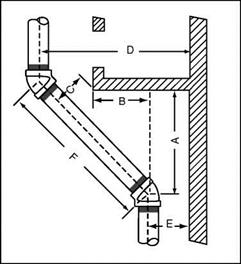
FIGURE 2.7 ■ Pipe offsets around obstructions.
|
pipe from the edge of the window. Using E to indicate the distance of the center of the rising pipe from the right edge of the window and D to indicate the center of the offset rising pipe from the right edge of the window, we can use the formula. Let’s see how it works.
To find the distance from the bottom of the window to the starting point of the offset, you would take the distance from the center of the riser to the left edge of the window (B) and add the distance from the corner of the left window edge to the center of the pipe (C) times 1.414. The formula would look like this: A = B + C X 1.414. Refer to Fig. 2.7 for an example. Now let’s put measurement numbers into the formula.
Assume that you want to find A. Further assume that B is equal to one foot and that C is equal to six inches. The numerical formula would be like this: A = 12 inches (B) + 6 inches (C) X 1.414 = 12 inches + 8V2 inches = 20V2 inches. This would prove that the upper 45° fitting would be 20V2 inches from the edge of the right edge of the window. As you can see, the actual procedure is not as difficult as the intimidation of using formulas might imply.
Posted by admin on 13/ 11/ 15
If you take a lot of pride in your work or are working to detailed piping diagrams, you may find that the spacing of your offsets must be equal. Equally – spaced offsets are not only more attractive and more professional looking, they might required. You can guess and eyeball measurements to get them close, but you will need a formula to work with if you want the offsets to be accurate. Fortunately, I can provide you with such a formula, and I will.
Again, we will concentrate on 45°, 60°, and 22V2° bends, since these are the three most often used in plumbing and pipefitting. We will start with the 45° turns. In our example, you should envision two pipes rising vertically. Each pipe will be offset to the left and then the pipes will continue to rise vertically. For a visual example, refer to Fig. 2.6. It is necessary for us to determine uniform symbols for what we are doing, so let’s get that out of the way right now.
In our measurement examples, we will refer to Spread, the distance between the two offsetting pipes from center to center, as A. Set will remain with the symbol of S. Travel will be T and it will be the same as Distance of D. Run will be noted by the letter R. The letter F will be the length of pipe threads.
Now for the deal. Travel is determined in an equally-offset pipe run at a 45° angle by multiplying the Set by 1.414. Run is found by multiplying Set by
|
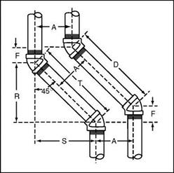
FIGURE 2.6 ■ Two-pipe 45° equal-spread offset.
|
1.000. The F measurement is found by multiplying the spread (A) by.4142. Remember that T and D are the same. Want to do the same exercise with a 60° setup? Why not?
To run a similar deal on 60° angles of equally – spaced offset pipes, you follow the same basic principles used in the previous example. Multiply the Set by 1.155 to find the Travel. Run is found by multiplying Set by.5773. The F measurement is found by multiplying the spread (A) by.5773. Remember that T and D are the same.
Need to find numbers for 22V2° bends? Well, it’s not difficult. To find figures for equally-spaced pipes with 22V2° bends, multiply the Set by 2.613 to find the Travel. Run is found by multiplying Set by 2.414. The F measurement is found by multiplying the spread (A) by.1989. Remember that T and D are the same.
Posted by admin on 12/ 11/ 15
Basic offsets are all based on the use of right triangles. You now know about Set and Travel. It is time that you learned about a term known as Run. Travel, as I said earlier, is the distance between center of two offset fittings that creates the length of a piece of pipe. This pipe’s length is determined as it develops from fitting to fitting, traveling along the angle of the offset. When you want to know the Run, you are interested in the distance measured along a straight line from the bottom horizontal pipe. Refer to Fig. 2.4 for an example
|
Inches
|
Decimal of an inch
|
|
Vf>4
|
.015625
|
|
Mu
|
.03125
|
|
M«4
|
.046875
|
|
VlS
|
.0625
|
|
Мб4
|
.078125
|
|
Mu
|
.09375
|
|
‘/64
|
.109375
|
|
Ms
|
.125
|
|
%4
|
.140625
|
|
Mu
|
.15625
|
|
"/S4
|
.171875
|
|
M,6
|
.1875
|
|
1 ,5/b4
|
.203125
|
|
Mu
|
.21875
|
|
‘Мб4
|
.234375
|
|
У*
|
.25
|
|
1?/б4
|
.265625
|
|
Мз2
|
.28125
|
|
‘%4
|
.296875
|
|
Mis
|
.3125
|
|
2 Vf»4
|
.328125
|
|
"Mu
|
.34375
|
|
2:!/s4
|
.359375
|
|
Ms
|
.375
|
|
3MS4
|
.390625
|
|
‘М32
|
.40625
|
|
ZMS4
|
.421875
|
|
Ml 6
|
.4375
|
|
29/s4
|
.453125
|
|
‘Mu
|
.46875
|
|
:,1/S4
|
.484375
|
|
‘/2
|
.5
|
|
Inches
|
Decimal of an inch
|
|
3M64
|
.515625
|
|
‘Mu
|
.53125
|
|
3M64
|
.546875
|
|
M.6
|
.5625
|
|
3Ms4
|
.578125
|
|
‘Mu
|
.59375
|
|
3Мб4
|
.609375
|
|
Ms
|
.625
|
|
41/64
|
.640625
|
|
2Mu
|
.65625
|
|
4M«4
|
.671875
|
|
"/is
|
.6875
|
|
4MS4
|
.703125
|
|
2Mu
|
.71875
|
|
4Мб4
|
.734375
|
|
3/4
|
.75
|
|
49/64
|
.765625
|
|
2Mu
|
.78125
|
|
51/64
|
.796875
|
|
‘Ml6
|
.8125
|
|
5M«4
|
,828125
|
|
2Mu
|
.84375
|
|
3Мб4
|
.859375
|
|
Ms
|
.875
|
|
SM«4
|
.890625
|
|
22/32
|
.90625
|
|
59/64
|
.921875
|
|
‘Mi 6
|
.9375
|
|
61/64
|
.953125
|
|
31/32
|
.96875
|
|
6Мб4
|
.984375
|
|
1
|
1
|
FIGURE 2.3 ■ Decimal equivalents of fractions of an inch.
|
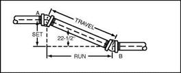
FIGURE 2.4 ■ Simple offsets.
|
|
of what I’m talking about. Run is a term applied to the horizontal measurement from the center of one offset fitting to the center of the other offset fitting.
Most charts and tables assign letters to terms used in formulas. For our purposes, let’s establish our own symbols. We will call the letter S—Set, the letter R-Run, and the letter T—Travel. What are common offsets in the plumbing and pipe fitting trade? A 45° offset is the most common. Two other offsets sometimes use are 60° bends and 22V2° bends. These are the three most frequently used offsets and the ones that we will concentrate our efforts on.
The use of the right triangle is important when dealing with piping offsets. The combination of Set, Travel, and Run form the triangle. I can provide you with a table that will make calculating offsets easier (Fig. 2.5), but you must still do some of the math yourself, or at least know some of the existing figures. This may seem a bit intimidating, but it is not as bad as you might think. Let me explain.
As a working plumber or pipe fitter, you know where your first pipe is. In our example earlier, where there was ductwork that needed to be cleared, you can easily determine what the measurement of the higher pipe must be. This might be determined by measuring the distance from a floor or ceiling. Either way, you will know the center measurement of your existing pipe and the center measurement for where you want the offset pipe to comply with. Knowing these two numbers will give you the Set figure. Remember, Set is measured as the vertical distance between the centers of two pipes. Refer back to Fig. 2.1 if you need a reminder on this concept.
Let’s assume that you know what your Set distance is. You want to know what the Travel is. To do this, use the table in 2.5. For example, if you were looking for the Travel of a 45° offset when the Set is known, you would multiply the Set measurement by a factor of 1.414. Now, let’s assume that you know the Travel and want to know the Set. For the same 45° offset, you would multiply the Travel measurement by.707. It’s really simple, as long you have the chart to use. The procedure is the same for different degrees of offset. Just refer to the chart and you will find your answers quickly and easily.
|
When
|
|
For
|
For
|
For
|
For
|
For
|
For
|
|
To
|
known
|
Multi-
|
60°
|
45°
|
30°
|
22V20
|
117.°
|
57«°
|
|
find
|
side
|
ply
|
ells
|
ells
|
ells
|
ells
|
ells
|
ells
|
|
side*
|
is
|
Side
|
by
|
by
|
by
|
by
|
by
|
by
|
|
T
|
S
|
s
|
1.155
|
1.414
|
2.000
|
2.613
|
5.125
|
10.187
|
|
s
|
T
|
T
|
.866
|
.707
|
.500
|
.383
|
.195
|
.098
|
|
R
|
s
|
s
|
.577
|
1.000
|
1.732
|
2.414
|
5.027
|
10.158
|
|
S
|
R
|
R
|
1.732
|
1.000
|
.577
|
.414
|
.198
|
.098
|
|
T
|
R
|
R
|
2.000
|
1.414
|
1.155
|
1.082
|
1.019
|
1.004
|
|
R
|
T
|
T
|
.500
|
.707
|
.866
|
.924
|
.980
|
.995
|
|
*S = set, R – run, T = travel.
|
FIGURE 2.5 ■ Multipliers for calculating simple offsets.
Finding Run measurements is no more difficult than Set or Travel. Say you have the Set measurement and want to know the Run figure for a 45° offset. Multiply the Set figure by 1.000 to get the Run number. If you are working with the Travel number, multiply that number by.707 to get the Run number for a 45° offset.
Posted by admin on 12/ 11/ 15
lumbing and pipe fitting are similar, but not always the same. Modern plumbers usually work with copper tubing and various forms of plastic piping. Cast-iron pipe is still encountered, and steel pipe is used for gas work. Finding a plumber working with threaded joints is not nearly as common as it once was. But, threaded pipe is still used in plumbing, and it is used frequently in pipe fitting. Figuring the fit for a pipe where threads are to be inserted into a fitting is a little different from sliding copper or plastic pipe into a hub fitting. However, many of the calculations used with threaded pipe apply to other types of pipe.
Many plumbers don’t spend a lot of time using mathematical functions to figure offsets. Heck, I’m one of them. How often have you taken a forty-five and held it out to guesstimate a length for a piece of pipe? If you have a lot of experience, your trained eye and skill probably gave you a measurement that was close enough for plastic pipe or copper tubing. I assume this because I do it all the time. But, there are times when it helps to know how to use a precise formula to get an accurate measurement.
   The need for accuracy is more important when installing threaded pipe. For example, you can’t afford to guess at a piece of gas pipe and find out the hard way that the threads did not go far enough into the receiving fitting. The need for accuracy is more important when installing threaded pipe. For example, you can’t afford to guess at a piece of gas pipe and find out the hard way that the threads did not go far enough into the receiving fitting.
In the old days, when I was first learning the trade, plumbers taught their helpers and apprentices. Those were the good-ole days. In today’s competitive market, plumbing companies don’t spend nearly as much time or money training their up-and-coming plumbers. As the owner of a plumbing company, I understand why this is, but I don’t agree with it. And, the net result is a crop
17
of plumbers who are not well prepared for what their trade requires. Sure, they can do the basics of gluing, soldering, and simple layouts, but many of the new breed don’t possess the knowledge needed to be true master plumbers. Don’t get me wrong; it’s not really the fault of the new plumbers. Responsibility for becoming an excellent plumber rests on many shoulders.
 ideally, plumbing apprentices and helpers should have classroom training. Company supervisors should authorize field plumbers some additional time for in-the-field training for apprentices. Working apprentices should go the extra mile to do research and study on their own. When I was helper, I used to spend my lunch break reading the codebook. There is no single individual to blame for the quality of education that some new plumbers are, or are not, receiving. Money is probably the root of the problem. Customers are looking for low bids. Contractors must be competitive, and this eliminates the ability to have a solid on-the-job training program. Many helpers today seem to be more interested in getting their check than getting an education. So, here we are, with a lot of plumbers who don’t know the inner workings of the finer points of plumbing. ideally, plumbing apprentices and helpers should have classroom training. Company supervisors should authorize field plumbers some additional time for in-the-field training for apprentices. Working apprentices should go the extra mile to do research and study on their own. When I was helper, I used to spend my lunch break reading the codebook. There is no single individual to blame for the quality of education that some new plumbers are, or are not, receiving. Money is probably the root of the problem. Customers are looking for low bids. Contractors must be competitive, and this eliminates the ability to have a solid on-the-job training program. Many helpers today seem to be more interested in getting their check than getting an education. So, here we are, with a lot of plumbers who don’t know the inner workings of the finer points of plumbing.
   I was fortunate enough to be what might have been the last generation of plumbers to get company support in learning the trade. Plenty of time was spent running jackhammers and using shovels, but my field plumber took the time to explain procedures to me. I learned quickly how to plumb a basic house. Then I learned how to run gas pipe and to do commercial buildings. As a part of my learning process, I read voraciously. Later I became a supervisor, then the owner of my own company, and eventually an educator for other plumbers and for apprentices. I could have stopped anywhere along the way, but I’ve taken my interest in the trade to the limits, and I continue to push ahead. No, I don’t know all there is to know, but I’ve worked hard to gain the knowledge I have. Now is the time for me to share my knowledge of pipe fitting math with you. I was fortunate enough to be what might have been the last generation of plumbers to get company support in learning the trade. Plenty of time was spent running jackhammers and using shovels, but my field plumber took the time to explain procedures to me. I learned quickly how to plumb a basic house. Then I learned how to run gas pipe and to do commercial buildings. As a part of my learning process, I read voraciously. Later I became a supervisor, then the owner of my own company, and eventually an educator for other plumbers and for apprentices. I could have stopped anywhere along the way, but I’ve taken my interest in the trade to the limits, and I continue to push ahead. No, I don’t know all there is to know, but I’ve worked hard to gain the knowledge I have. Now is the time for me to share my knowledge of pipe fitting math with you.
45° OFFSETS
Offsets for 45° bends are common needs in both plumbing and pipe fitting. In fact, this degree of offset is one of the most common in the trade. I mentioned

|
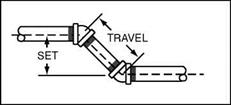
FIGURE 2.1 ■ Calculated 45° offsets.
|
|
earlier that many plumbers eyeball such offset measurements. The method works for a lot of plumbers, but let’s take a little time to see how the math of such offsets can help you in your career.
To start our tutorial, let’s discuss terms that apply to offsets. Envision a horizontal pipe that you want to install a 45° offset in. For the ease of vision, think of the horizontal pipe resting in a pipe hanger. You have to offset the pipe over a piece of ductwork. This will have a 45° fitting looking up from your horizontal pipe. There will be a piece of pipe in the upturned end of the fitting that will come into the bottom of the second 45° fitting (Fig. 2.1: offset drawing).
 As we talk about measurements here, they will all be measured from the center of the pipe. There are two terms you need to know for this calculation. As we talk about measurements here, they will all be measured from the center of the pipe. There are two terms you need to know for this calculation.
Travel, the first term, is the length of the pipe between the two 45° fittings. The length of Travel begins and ends at the center of each fitting. The distance from the center of the lower horizontal pipe to the center of the upper horizontal pipe is called the Set. Now that you know the terms, we can do the math.
To make doing the math easier, I am including tables for you to work from (Fig. 2.2: 45° offset math tables). Let’s say that the Set is 563/4 inches. Find this measurement in the table in Fig. 2.2. This will show you that the Travel is 80.244 inches. Now you can use the table for converting decimal equivalents of fractions of an inch (Fig. 2.3: decimal equivalents of fractions of an inch) to convert your decimal, the 80.244 inches. Finding the decimal equivalent of a fraction is a matter of dividing the numerator by the denominator. The chart in Fig. 2.3 proves the measurement to be 80V4 inches. You can find the Set if you know the Travel by reversing the procedure.
If the Travel is known to be 80V4 inches, what is the Set? We both know that it is 563/4 inches, but how would you find it? Use the table in Fig. 2.2 and look under the heading of Travel. Find the 80.244 listing that represents 80V4 inches. Refer to the Set heading. What does it say? Of course, it says 563/4. It’s that easy. All you have to do is use the tables that I’ve provided to make your life easier in calculating 45° offsets.
|
Set
|
Travel
|
Set
|
Travel
|
Set
|
Travel
|
|
2
|
2.828
|
У,
|
15.907
|
Vh
|
28.987
|
|
‘/4
|
3.181
|
y2
|
16.261
|
3/4
|
29.340
|
|
y2
|
3.531
|
%
|
16.614
|
21
|
29.694
|
|
3/4
|
3.888
|
12
|
16.968
|
Va
|
30.047
|
|
3
|
4.242
|
У4
|
17.321
|
y2
|
30.401
|
|
‘/4
|
4.575
|
У2
|
17.675
|
3/4
|
30.754
|
|
‘/2
|
4.949
|
%
|
18.028
|
22
|
31.108
|
|
3A
|
5.302
|
13
|
18.382
|
У,
|
31.461
|
|
4
|
5.656
|
У4
|
18.735
|
y2
|
31.815
|
|
‘/4
|
6.009
|
y2
|
19.089
|
3/4
|
32.168
|
|
y2
|
6.363
|
%
|
19.442
|
23
|
32.522
|
|
3A
|
6.716
|
14
|
19.796
|
y4
|
32.875
|
|
5
|
7.070
|
y4
|
20.149
|
Уа
|
33.229
|
|
У.
|
7.423
|
y2
|
20.503
|
3/4
|
33.582
|
|
y2
|
7.777
|
%
|
20.856
|
24
|
33.936
|
|
3A
|
8.130
|
15
|
21.210
|
y4
|
34.289
|
|
6
|
8.484
|
‘/4
|
21.563
|
y2
|
34.643
|
|
У.
|
8.837
|
y2
|
21.917
|
3/4
|
34.996
|
|
y2
|
9.191
|
%
|
22.270
|
25
|
35.350
|
|
3/>
|
9.544
|
16
|
22.624
|
У4
|
35.703
|
|
7
|
9.898
|
•Л
|
22.977
|
y2
|
36.057
|
|
У.
|
10.251
|
Vz
|
23.331
|
%
|
36.410
|
|
Vz
|
10.605
|
%
|
23.684
|
26
|
36.764
|
|
%
|
10.958
|
17
|
24.038
|
У4
|
37.117
|
|
8
|
11.312
|
V4
|
24.391
|
y2
|
37.471
|
|
‘/4
|
11.665
|
У2
|
24.745
|
%
|
37.824
|
|
‘/2
|
12.019
|
3/4
|
25.098
|
27
|
38.178
|
|
%
|
12.372
|
18
|
25.452
|
1/4
|
38.531
|
|
9
|
12.726
|
‘/4
|
25.805
|
y2
|
38.885
|
|
y4
|
13.079
|
y2
|
26.159
|
3/4
|
39.238
|
|
‘/2
|
13.433
|
%
|
26.512
|
28
|
39.592
|
|
3/4
|
13.786
|
19
|
26.866
|
У4
|
39.945
|
|
10
|
14.140
|
%
|
27.219
|
y2
|
40.299
|
|
‘/4
|
14.493
|
y2
|
27.573
|
3/4
|
40.652
|
|
‘/2
|
14.847
|
3/4
|
27.926
|
29
|
41.006
|
|
%
|
15.200
|
20
|
28.280
|
У4
|
41.359
|
|
11
|
15.554
|
У4
|
28.635
|
y2
|
41.713
|
FIGURE 2.2 ■ Set and travel relationships in inches for 45° offsets.
Posted by admin on 12/ 11/ 15
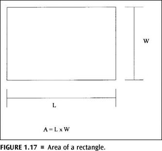
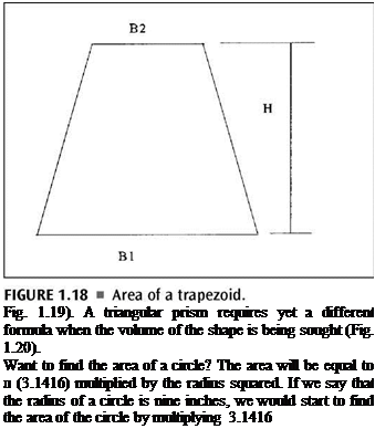
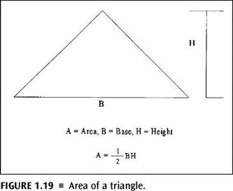
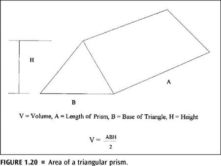
Finding the area of a given shape is also done with the use of formulas. It’s no more difficult than what we have already been doing. In some ways, finding the area is easier than finding the perimeter. Most anyone in the trades knows how to find the square footage of a room. When you multiply the length of the room by the width of the room, you arrive at the square footage (Fig. 1.17). Well, this is exactly how you find the area of a rectangle or a square. There is no mystery or trick. Just multiply the length by the width for a rectangle or multiply one side by another side for a square, and you will have the area of the shape. To find the volume of a rectangle, you simply multiply the length by the width by the height. Different formulas are needed to find the area of trapezoids and triangles (Fig. 1.18 and
|
|
 |
|
|
|
|
(тс) by 9 inches by 9 inches. This would advance up to multiplying 3.1416 by 81 square inches (9 X 9 = 81). The area of the circle would turn out to be 254.47 square inches. If you are looking for the volume of a cube, you simply multiply the three sides, as is illustrated in Figure 1.21. For a trapezoidal prism, the volume is found by using the formula in Figure 1.22.
|
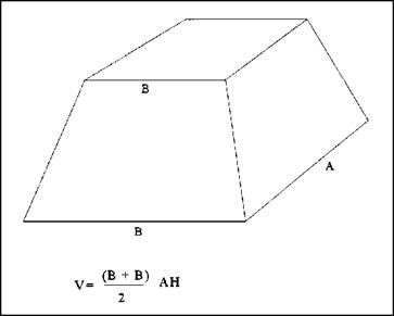
FIGURE 1.22 ■ Volume of a trapeziodal prism.
|
The math that is used in plumbing and pipe fitting is not very difficult to understand if you will accept the fact that it is necessary and that you need to understand it. What may appear daunting on the surface is actually pretty practical in principle. With a combination of reference tables, a good calculator, and a little effort, you can accomplish your needs for math within the trade quickly.
Posted by admin on 12/ 11/ 15
Triangle perimeters are not difficult to establish. The process is similar to the one used with squares, only there is one less measurement. To find the perimeter of a triangle, add up the sum total of the three sides of the shape. if you want a formula to use, it could look like this: P = A + B + C. The long and the short of it, no pun intended, is that you simply add up the three dimensions and you have the perimeter.
Circles
Circles can give you some trouble when you are looking for their perimeters, which should really be called their circumference. I have provided resource tables in the next chapter that will help you to avoid doing the math to find the circumference of a circle, but we should at least take a few moments to
|
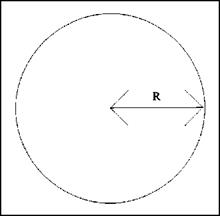
FIGURE 1.15 ■ Radius of a circle.
|
|
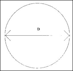
FIGURE 1.16 ■ Diameter of a circle.
|
explore the procedure while we are here. Circles can be tricky, but they aren’t really all that tough. Let’s look at a couple of formulas that you shouldn’t experience problems with (Fig. 1.16).
When you want to find the circumference of a circle, you must work with the diameter (D), the radius (R), and л, which is 3.1416. You can use one of two formulas to solve your problem, depending on which variable is known. If you know the diameter, use the following formula: C = л d. When you know the radius, use this formula: C = 2лг. If the diameter is six inches, your formula would reveal that pi (3.1416) times 6 inches equals 18.8496 inches. This number would be rounded to 18.85 inches. If you knew the radius and not the diameter, your numbers would be 2 times л (3.1416) times 3 inches. The same answer would be arrived at, for a circumference of 18.85 inches. The formulas are not difficult, but using the tables in the next chapter might be faster and easier for you.
Posted by admin on 12/ 11/ 15
A little geometry is needed in the plumbing trade. Whether you are working with roof drains, figuring floor drains, or doing almost any part of plumbing paperwork, you may be using geometry. I hated geometry in school, but i’ve learned how to use it in my trade and how to make the use of it much more simple than I ever used to know it to be. I’ll share some of my secrets on the subject.
Plumbers use geometry to find the distance around objects, to find the area of objects, to determine volume capacities, and so forth. A lot of plumbers probably don’t think about what they are doing as geometry, but it is. So, let me show you some fast ways to solve your on-the-job problems by using geometry that you may not even realize is geometry. Think of what we are about to do as just good old plumbing stuff that has to be done.
Rectangles
Rectangles are squares, right? Wrong, they are rectangles. Squares are squares. Got ya! Now that I have your attention, let’s talk about the methods used to determine perimeter measurements for a rectangle. A flat roof on a commercial building is a good example of a rectangle that a plumber might need to work with for rainwater drainage. This exercise is too simple. To find the perimeter (P), you multiply the length (L) by 2 and add it to the width (W) that has also been multiplied by two. The formula looks like this: P = 2L X 2W. Now let’s put this into real numbers. Assume that you have a roof that is 80 feet long and 40 feet wide. What is the perimeter of the roof? First, do the math for the length. Taking 80 X 2 will give you 160. Do the width next. You will find that 40 X 2 is 80. When you add the 80 to the 160, you get 240, which is the perimeter of the roof. Not too tough, huh? Didn’t I tell you that I’d make this stuff easy?
A Square
A square has a perimeter measurement. Do you know how to find it? This one really is too simple. Add up the measurements of the four equal sides and you have the perimeter. in other words, if you are dealing with a flat roof that is square with dimensions of 50 feet on each side, the perimeter is 200 feet. This is established by multiplying 50 X 4. They don’t get any easier than this one.
| |


 Let me set the stage for a graphic example of getting around an overhead obstruction. Assume that you are bringing a pipe up and out of a concrete floor in a basement. There is a window directly above the pipe that you must offset around. The window was an afterthought. Having the pipe under the window was not a mistake in the groundworks rough-in. However, it is your job to move the pipe, without breaking up the floor, to get around the window.


 The need for accuracy is more important when installing threaded pipe. For example, you can’t afford to guess at a piece of gas pipe and find out the hard way that the threads did not go far enough into the receiving fitting.
 ideally, plumbing apprentices and helpers should have classroom training. Company supervisors should authorize field plumbers some additional time for in-the-field training for apprentices. Working apprentices should go the extra mile to do research and study on their own. When I was helper, I used to spend my lunch break reading the codebook. There is no single individual to blame for the quality of education that some new plumbers are, or are not, receiving. Money is probably the root of the problem. Customers are looking for low bids. Contractors must be competitive, and this eliminates the ability to have a solid on-the-job training program. Many helpers today seem to be more interested in getting their check than getting an education. So, here we are, with a lot of plumbers who don’t know the inner workings of the finer points of plumbing.
 I was fortunate enough to be what might have been the last generation of plumbers to get company support in learning the trade. Plenty of time was spent running jackhammers and using shovels, but my field plumber took the time to explain procedures to me. I learned quickly how to plumb a basic house. Then I learned how to run gas pipe and to do commercial buildings. As a part of my learning process, I read voraciously. Later I became a supervisor, then the owner of my own company, and eventually an educator for other plumbers and for apprentices. I could have stopped anywhere along the way, but I’ve taken my interest in the trade to the limits, and I continue to push ahead. No, I don’t know all there is to know, but I’ve worked hard to gain the knowledge I have. Now is the time for me to share my knowledge of pipe fitting math with you.

 As we talk about measurements here, they will all be measured from the center of the pipe. There are two terms you need to know for this calculation.


