Category PLUMBER’S AND. PIPE FITTER’S. CALCULATIONS MANUAL

CHOOSING MATERIALS

Choosing materials for a venting system is not usually much problem. Most jobs use Schedule-40 plastic pipe for vent pipes. There are, however, other options for vent materials. And, not all codes allow the same types of vent ma­terials. You will also notice from the following tables of approved materials that there can be a difference in approved materials for vents that are installed underground, compared to those installed above ground. We will close out this chapter with tables that indicate what types of materials are allowed within major plumbing codes.

Cast iron

ABS*

PVC*

Copper

Brass

Lead


Cast iron

ABS

PVC

Copper

Galvanized

Lead

Aluminum Borosilicate Glass Brass


*These materials may not be used with buildings having more than three floors above grade.


FIGURE 5.49 ■ Materials approved for above-ground vents in Zone Two. (Courtesy of McGraw-Hill)

FIGURE 5.51 ■ Materials approved for underground vents in Zone One. (Courtesy of McGraw-Hill)

Подпись: Cast iron ABS PVC Copper Galvanized Lead Aluminum Brass

Подпись: Cast iron ABS PVC Copper Aluminum Borosilicate glass

FIGURE 5.50 ■ Materials approved for above-ground vents in Zone Three. (Courtesy of McGraw-Hill)

FIGURE 5.52 ■ Materials approved for underground vents in Zone Two. (Courtesy of McGraw-Hill)

Cast iron ABS PVC Copper


This page intentionally left blank.

RISER DIAGRAMS

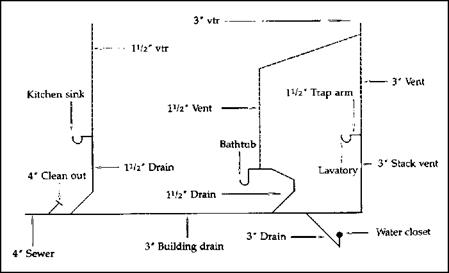
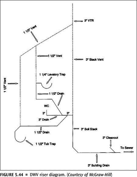
Riser diagrams are often required by code officers prior to any plumbing be­ing installed. Supplying a detailed riser diagram (Fig. 5.44 and Fig. 5.45) is usu­ally a standard part of a permit applica­tion. You can also use riser diagrams to help you when sizing a vent system. If

RISER DIAGRAMS

FIGURE 5.45 ■ DWV riser diagram, with size and location of pipes. (Courtesy of TAB Books, Home Plumbing Illustrated, by R. Dodge Woodson, p. 50)

RISER DIAGRAMS

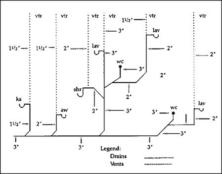
FIGURE 5.46 ■ Poorly designed DWV layouts. (Courtesy of TAB Books, Home Plumbing Illustrated, by R. Dodge Woodson, p. 55)

RISER DIAGRAMS
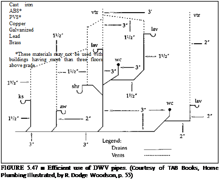
you draw a riser for the job you are working with, the diagram will make it easier for you to label the fixture-unit loads and the sizes of the vents re­quired. Another good use of a riser diagram is to minimize wasted piping. If you draw your piping path on paper, you can spot situations where an alter­native plan might be used to minimize the cost of labor and materials (Fig. 5.46 and Fig. 5.47).

SUPPORTING A VENT SYSTEM

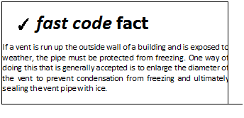
Подпись: ✓ fast code fact If a vent is run up the outside wall of a building and is exposed to weather, the pipe must be protected from freezing. One way of doing this that is generally accepted is to enlarge the diameter of the vent to prevent condensation from freezing and ultimately sealing the vent pipe with ice.

SUPPORTING A VENT SYSTEM Подпись: Support material Maximum distance between supports (ft)

Supporting a vent system is another element of a system design. The spac­ing allowed for support varies from code to code and with the type of pipe being used in the vent system. The tables below will show you some examples of recommended minimums for support spacing.

SUPPORTING A VENT SYSTEM
Подпись: Lead pipe Cast iron Galvanized Copper PVC ABS Подпись: Type of vent pipe Maximum distance between supports

FIGURE 5.38 ■ Horizontal pipe-support intervals in Zone Two. [Courtesy of McGraw-Hill)

FIGURE 5.39 ■ Vertical pipe-support intervals in Zone One. [Courtesy of McGraw-Hill)

SUPPORTING A VENT SYSTEM

Type of vent pipe Maximum distance between supports (ft)


ABS

Cast iron

Galvanized

PVC

Copper (2 in and larger) Copper (ІУ2 in and smaller)


SUPPORTING A VENT SYSTEM

Maximum distance between supports (ft)


Lead pipe

4

Cast iron

At each storyt

Galvanized

At each storyt

Copper (ІУ4 in)

4

Copper (ІУ2 in and larger)

At each story

PVC (ІУ2 in and smaller)

4

PVC (2 in and larger)

At each story

ABS (1У2 in and smaller)

4

ABS (2 in and larger)

At each story

Type of vent pipe

*A11 stacks must be supported at their bases. tSupport intervals may not exceed 15 ft. tSupport intervals may not exceed 30 ft.

SUPPORTING A VENT SYSTEM

FIGURE 5.41 ■ Vertical pipe-support intervals in Zone Two. (Courtesy of McGraw-Hill)

Подпись: Type of vent pipe Maximum distance between supports (ft)

FIGURE 5.42 ■ Horizontal pipe-support intervals in Zone Three. (Courtesy of McGraw-Hill)

Lead pipe

4

Cast iron

15

Galvanized

15

Copper tubing

10

ABS

4

PVC

4

Brass

10

Aluminum

15

SUPPORTING A VENT SYSTEM

SUPPORTING A VENT SYSTEM

Подпись: ► sensible shortcutПодпись: A rule of thumb for hanger spacing when working with plastic vent piping is to support the pipe at intervals that do not exceed four feet from the center of one support to the center of the next support.

SUMP VENTS

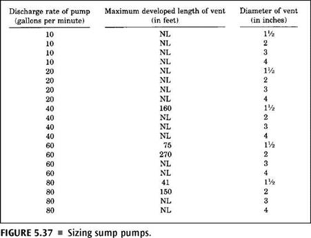
Sump vents, the ones used to vent a sump system, are calculated on a basis of a pump’s discharge capacity. Tables are often provided for this type of sizing. See Figure 5.37 for an example of such a table. Using a table like this one, you can quickly and easily size a vent for a sump. As long as you know the discharge rate of the pump being used in the sump, the rest of the work is simple.

SUMP VENTS

SUMP VENTS

WET VENTING

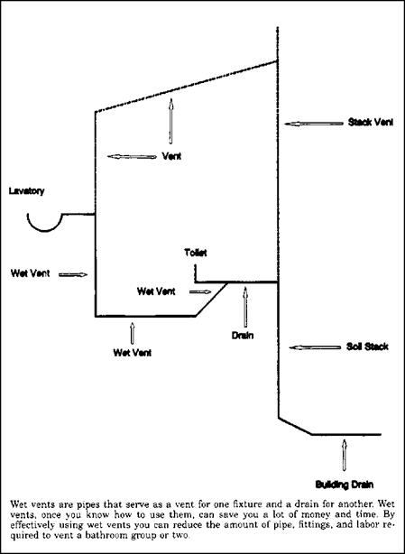
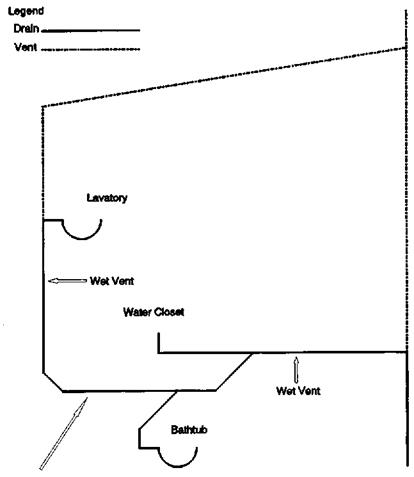
Wet venting is popular, but a little different when it comes to sizing the vents. Tables can still be used for this type of sizing. Look at Figure 5.34 for an ex­ample of a table that might be used to size a wet stack vent. Another type of table that you might encounter is shown in Figure 5.35. This table is intended for use in sizing a vent stack for wet venting.

Keep in mind that not all plumbing codes are the same, and they may present their information differently. It is also important to remember that re­quirements may be different.

Fixture-unit value as load factors

Minimum siz trap (in)

2

U/2

2

2

3

3

1У>

8

3

3

3

2

2

4

1У2

8

Note 6

4

Note 6

4

Note 6

3

2

2

Nominal 1У2

3

Note 6

4

Note 6

6

Note 6


Fixture type

Laundry tray (1 or 2 compartments)

Shower stall, domestic Showers (group) per head2

Sinks

Surgeon’s

Flushing rim (with valve) Service (trap standard)

Service (“p” trap)

Pot, scullery, etc.2

Urinal, pedestal, siphon jet, blowout

Urinal, wall lip Urinal, Washout Washing machines (commercial)3 Washing machine (residential)

Wash sink (circular or multiple) each set of faucets

Water closet, flushometer tank, public or private

Water closet, private installation Water closet, public installation


1 in = 25.4 mm

Notes:

1. A showerhead over a bathtub or whirlpool bathtub attachments does not in­crease the fixture value.

2. See Figures 12.33 and 12.34 for methods of computing unit value of fixtures not listed in Figure 12.32 or for rating of devices with intermittent flows.

3. See Figure 12.33.

4. Lavatories with VA or 1 Winch trap have the same load value; larger P. O. plugs have greater flow rate.

5. Size of floor drain shall be determined by the area of the floor to be drained. The drainage fixture unit value need not be greater than 1 unless the drain re­ceives indirect discharge from plumbing fixtures, air conditioner or refrigeration equipment.

6. Trap size shall be consistent with fixture type as defined in industry stan­dards.


FIGURE 5.32 ■ (Continued) Fixture units per fixture or group. (Courtesy of Standard Plumbing Code)


WET VENTING

FIGURE 5.33 ■ Fixtures not listed. (Courtesy of Standard Plumbing Code)


Stack pipe size Fixture-unit load on stack Maximum length of stack (ft)


30

50

100

300


2

4

3

24

4

50

6

100


WET VENTING Подпись: Vent-stack size requirements (in) 2 2‘/2 3 4

FIGURE 5.34 ■ Table for sizing a wet stack vent in Zone Two. (Courtesy of McGraw-Hill)

FIGURE 5.35 ■ Table for sizing a vent stack for wet venting in Zone Two. (Courtesy of McGraw-Hill)

STACK VENTS, VENT STACKS, AND RELIEF VENTS

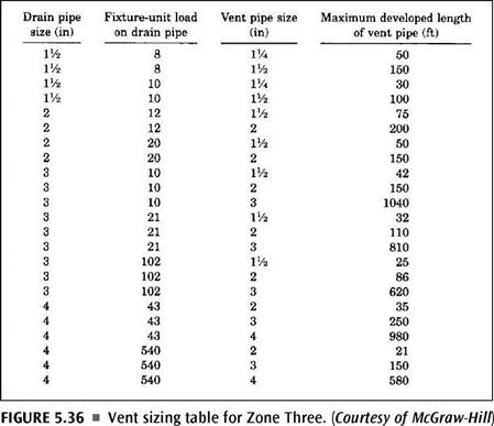
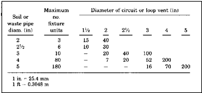
Stack vents, vent stacks, and relief vents require more information for sizing. Specifically, you must know the fixture-unit load on a drain before you can determine vent sizing and developed lengths. Once you have calculated the fixture units, a sizing table can be used to give you your sizing information. The table shown in Figure 5.31 is the type of table that would be used to de­fine the requirements of stack vents, vent stacks, and relief vents. Like the other tables, this one is self-explanatory. To prove this, size the diameter and maximum length of a vent stack that will serve 20 fixture units with a drain di­ameter of two inches. Assume that you want your vent pipe to have a diame­ter of one and a half inches. The answer is that your vent size is okay, as long as you don’t extend it more than 50 feet. If you need more distance, increase the size of the vent to a 2-inch diameter and feel free to run the vent up to 150 feet. The table is easy to use, but you must be able to calculate the load of fixture units. How will you do that? I’ll show you.

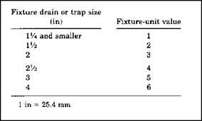
Подпись:Most codebooks will provide you with some form or a chart or table that identifies fixture-units for drainage piping. A table like the one in Figure 5.32 is quite helpful. By looking at such a table, you can quickly determine the load, in terms of fixture units, that an individual fixture puts on a drain. For example, a bidet carries a fixture-unit rat­ing of 2. A drinking fountain is rated for one half of a fixture unit. A residential wa­ter closet is worth 4 fixture units. By using this type of table to assign fixture-unit rat­ings to all fixtures being served by a drain, you can then arrive at a number to use with the vent-sizing table. For fixtures that are not listed, you can use a generic table, like the one in Figure 5.33, to assign ratings for fixture units.

‘О

оо


Подпись: PLUMBER’S AND PIPE FITTER’S CALCULATIONS MANUAL
STACK VENTS, VENT STACKS, AND RELIEF VENTS

FIGURE 5.30 ■ Individual and branch vent sizing table for horizontal soil and waste branches. [Courtesy of Standard Plumbing Code)

Size of soil or

Diameter of vent required (in)

(in)

connected

lVi

1У2

2

2У2

3

4

5

6

8

V/i

2

30

1V5>

8

50

150

1У2

10

30

100

2

12

30

75

200

2

20

26

50

150

2’/2

42

30

100

300

3

10

30

100

200

600

3

30

60

200

500

3

60

50

80

400

4

100

35

100

260

1000

4

200

30

90

250

900

4

500

20

70

180

700

5

200

35

80

350

1000

5

500

30

70

300

900

5

1100

20

50

200

700

6

350

_

_

25

50

200

400

1300

6

620

15

30

125

300

1100

6

960

—•

24

100

250

1000

6

1900

20

70

200

700

8

600

50

150

500

1300

8

1400

_

_

_

__

_

40

100

400

1200

8

2200

30

80

350

1100

8

3600

25

60

250

800

10

1000

75

125

1000

10

2500

50

100

500

10

3800

_

_

_

30

80

350

10

5600

25

60

250

1 in = 25.4 mm 1 ft = 0.3048 m

Подпись: VENT SYSYEM CALCULATIONSFIGURE 5.31 ■ Maximum length of stack vents, vent stacks, and relief vents. (Courtesy of Standard Plumbing Code)

‘O

SO


Fixture type

Fixture-unit value as load factors

Minimum size of trap (in)

Bathroom group consisting of water closet, lavatory, and bathtub or shower

6

Bathtub1 (with or without overhead shower) or whirlpool attachments

2

lVz

Bidet

2

Nominal 1У2

Combination sink and tray

3

T/2

Combination sink and tray with food disposal unit

4

Separate traps ІУ2

Dental unit or cuspidor

1

1У4

Dental lavatory

1

1У4

Drinking fountain

‘/2

1

Dishwashing machine2 domestic.

2

1У2

Floor drains5

1

2

Kitchen sink, domestic

2

1У2

Kitchen sink, domestic with food waste grinder and/or dishwasher

3

1У2

Lavatory4

1

Small P. O. l’/4

Lavatory4

2

Large P. O. 1У2

Lavatory, barber, beauty parlor

2

ІУ2

Lavatory, surgeon’s

2

ІУ2

FIGURE 5.32 ■ Fixture units per fixture or group. (Courtesy of Standard Plumbing Code)

A SIZING EXERCISE

Подпись:A SIZING EXERCISE
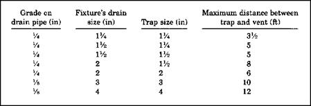
Let’s do a sizing exercise to illustrate how the tables from a codebook might be used to determine the size of piping needed for various vents. When you set up a vent sys­tem, you must know how far a vent is al­lowed to be from the trap it is serving. If you look at Figure 5.27, you will see the re­quirements for one of the major plumbing codes. The table is easy enough to understand. If you have a fixture drain that has a diameter of 1.5 inches and a trap size of 1.5 inches, with a grade of a quarter of an inch per foot, the trap may be as much as five feet from the vent. With this particular code, the dis­tance would remain the same, even if the trap size was only one and a quarter inches in diameter, so long as the drain remains as a 1.5 inch diameter.

Size of fixture drain (in)

Size of trap (in)

Fall (in/ft)

Max. distance from trap

lVi

1У4

У.

3 ft 6 in

1У2

1У4

У4

5 ft

1У2

1У2

Va

5 ft

2

1У2

Va

8 ft

2

2

Va

6 ft

3

3

Vs

10 ft

4

4

Vs

12 ft

1 in = 25,4 mm 1 ft = 0.3048 m

FIGURE 5.27 ■ Distance of fixture trap from vent. (Courtesy of Standard Plumbing Code)
A SIZING EXERCISEIf the size of the fixture drain was three inches in diameter, with a 3-inch trap, and one-eighth of an inch of fall per foot, the vent could be up to 10 feet from the trap. Obviously, this type of table is easy to understand and to work with.

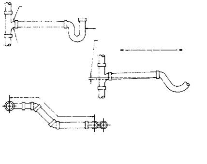
Vent sizing is based on developed length. This is the measured distance of all pipe used in the system. Measurements are taken on a center-to-center basis. You can see in Figure 5.28 how the measurements are assessed. Once you know the developed length of a vent, you can use a sizing chart to de­termine the minimum diameter of the vent pipe. The sizing of a vent or vent system is not difficult. Let me show you how it’s done.

A SIZING EXERCISE A SIZING EXERCISE

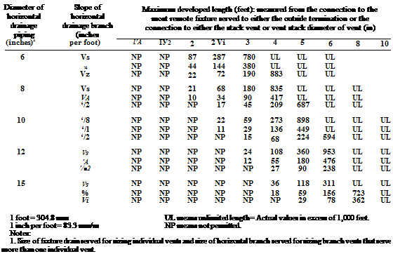
Look at Figure 5.29. This is a chart designed for sizing individual and branch vents serving horizontal soil and waste branches. As you look at the table, you will see two types of abbreviations. The abbreviation shown as NP means "Not Permitted". When you see the abbreviation of UL, it means "Un­limited". Aside from these two clarifications, the table pretty much speaks for itself. Try to find the answer to the question I’m about to give you. Assume that you have a drain that has a 2-inch diameter. The amount of fall on the pipe is set at one quarter of an inch per foot. You want to run a vent with a di­ameter of 1.5 inches. How far can you run the vent in that size? The answer is that there is no limit to the length of the vent run. But, suppose you wanted the vent diameter to be 1.25 inch, how far could it go? A vent of this size

FIGURE 5.28 ■ Distance of fixture trap from vent. (Courtesy of Standard Plumbing Code)

‘чО

O’*


Подпись: PLUMBER’S AND PIPE FITTER’S CALCULATIONS MANUAL

Diameter of horizontal drainage piping (inches)1

Slope of horizontal drainage branch (inches per foot)

Maximum developed length (feet): measured from the connection to the most remote fixture served to either the outside termination or the connection to either the stack vent or vent stack diameter of vent (in)

ІУ4

ІУ2

2

2У2

3

4

5 6 8 10

IV*

V4

UL3

У2

UL

l‘/2

‘/4

UL

UL

Vi

UL

UL

2

Vi

874

UL

UL

V’2

437

UL

UL

2 Vi

‘Л

286

756

UL

UL

Vi

143

378

UL

UL

3

V. в

NP

606

UL

UL

UL

‘/4

NP

303

UL

UL

UL

‘/2

NP

152

704

UL

UL

4

Уя

NP

NP

666

UL

UL

UL

‘/4

NP

NP

333

UL

UL

UL

*/2

NP

NP

166

548

UL

UL

5

‘/я

NP

NP

218

716

UL

UL

UL

‘/4

NP

NP

109

358

948

UL

UL

‘/2

NP

NP

54

179

474

UL

UL


FIGURE 5.29 ■ Individual and branch vent sizing table for horizontal soil and waste branches. [Courtesy of Standard Plumbing Code)

could run for a developed length of 874 feet, which is far more than you would be likely to run it.

Now assume that you have a 3-inch drain and you want to run a vent that has a diameter of 1.25 inches. How far can it go? It can’t be used. This is in­dicated by the NP symbol. The reason for this is that the vent must be at least half the size, in diameter, of what the drain being served is. There are excep­tions to this rule as the size of drains become larger. This means that the smallest vent diameter allowed for a 3-inch drain is a 1.5-inch vent. A vent of this size could run for 606 feet. When you deal with large-diameter drains, you have to move up to larger vent sizes to achieve unlimited runs of distance. This can be seen in Figure 5.30. You would use the table in Figure 5.30 in the same way that we used the previous sizing table.

SIZING TABLES

Sizing tables are often used when sizing vent pipes (Fig. 5.21). There can be many different types of tables to use during a sizing procedure. For example,

lVa

’Л

lVi

Unlimited

lVi

V4

1V2

Unlimited

2

Vi

1 Vi

290

2

Vi

lVi

Unlimited

3

Vi

1V2

97

3

Vi

2

420

3

Vi

3

Unlimited

4

Vi

2

98

4

Vi

3

Unlimited

4

Vi

4

Unlimited

Drain pipe size (in)

Drain pipe size

(in/ft)

Vent pipe size (in)

Maximum developed length of vent pipe (ft)

FIGURE 5.21 ■ Vent sizing table for Zone Three (for use with individual, branch, and circuit vents for horizontal drain pipes). (Courtesy of McGraw-Hill)

Подпись: Wet-vented fixtures 1 to 2 Bathtubs or showers 3 to 5 Bathtubs or showers 6 to 9 Bathtubs or showers 10 to 16 Bathtubs or showers Подпись: Stack size required (inches) 2 2 Vi 3 4

you might use one table to size a vent stack (Fig. 5.22) and another table to size a wet stack vent (Fig. 5.23). Some codes might use one table for both types of vents (Fig. 5.24). Then you might have a different table to use when sizing branch vents or circuit vents (Fig. 5.25). Battery vents may require a dif­ferent table (Fig. 5.26). Once you have a sizing table to work with, sizing a vent system is not a complicated process.

FIGURE 5.22 ■ Sizing a vent stack for wet-venting in Zone Two. (Courtesy of McGraw-Hill)

Pipe size of stack (inches)

Fixture-unit load on stack

Maximum length of stack

2

4

30

3

24

50

4

50

100

6

100

300

FIGURE 5.23 ■ Sizing a wet stack vent in Zone Two. (Courtesy of McGraw-Hill)

Drain pipe size (inches)

Fixture-unit load on drain pipe

Vent pipe size (inches)

Maximum developed length of vent pipe (feet)

VA

8

VA

50

VA

8

VA

150

VA

10

VA

30

llA

10

VA

100

2

12

VA

75

2

12

2

200

2

20

VA

50

2

20

2

150

3

10

VA

42

3

10

2

150

3

10

3

1040

3

21

VA

32

3

21

2

110

3

21

3

810

3

102

VA

25

3

102

2

86

3

102

3

620

4

43

2

35

4

43

3

250

4

43

4

980

4

540

2

21

4

540

3

150

4

540

4

580

FIGURE 5.24 ■ Vent sizing for Zone Three (for use with vent stacks and stack vents). (Courtesy of McGraw-Hill)

Drain pipe size (inches)

Drain pipe grade per foot (inches)

Vent pipe size (inches)

Maximum developed length of vent pipe (feet)

1У2

Vi

I1/*

Unlimited

VA

%

ІУ2

Unlimited

2

lA

lVi

290

2

‘A

VA

Unlimited

3

Vi

VA

97

3

Vi

2

420

3

‘/4

3

Unlimited

4

Vi

2

98

4

‘/4

3

Unlimited

4

Vi

4

Unlimited

FIGURE 5.25 ■ Vent sizing for Zone Three (for use with individual, branch, and circuit vents for horizontal drain pipes. (Courtesy of McGraw-Hill)

DISTANCE FROM TRAP TO VENT

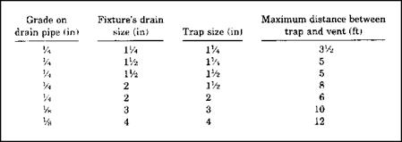
The distance from a trap to a vent is determined by local plumbing code re­quirements. Allowable distances are usually given either in text or in tables within a codebook. There can be a sig­nificant difference from one code to the other. To illustrate this, I’d like you to refer to Figures 5.18, 5.19, and 5.20. The tables you see in these illustrations represent differences between three major plumbing codes. You should no­tice that the distances from traps to vents is the same for two codes and dif­ferent for one code. You must refer to the plumbing code that is being en­forced in your area for specific sizing requirements. The information pro­vided here is representative of the types of charts, tables, and information you will likely work with, but it is not necessarily the code that you will be

Grade on drain pipe (in)

Size of trap arm (in)

Maximum distance between trap and vent (ft)

У4

1У4

2У2

У4

1У2

ЗУ2

У4

2

5

Vi

3

6

Vi

4 and larger

10

FIGURE 5.18 ■ Trap-to-vent distances in Zone One. (Courtesy of McGraw-Hill)

DISTANCE FROM TRAP TO VENT

FIGURE 5.19 ■ Trap-to-vent distances in Zone Two. (Courtesy of McGraw-Hill)

DISTANCE FROM TRAP TO VENT

FIGURE 5.20 ■ Trap-to-vent distances in Zone Three. (Courtesy of McGraw-Hill)

working with. Our intent here is to learn how to size systems, so consider the information here as a learning tool, rather than a code ruling.

TYPES OF VENTS

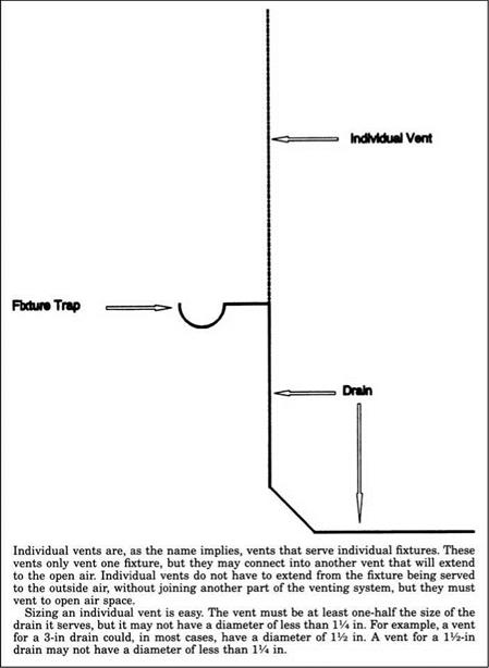
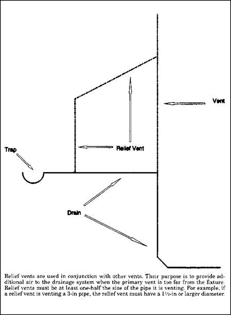
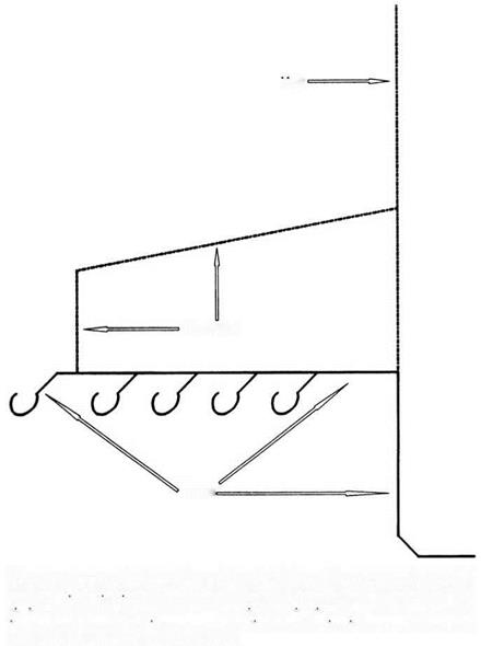
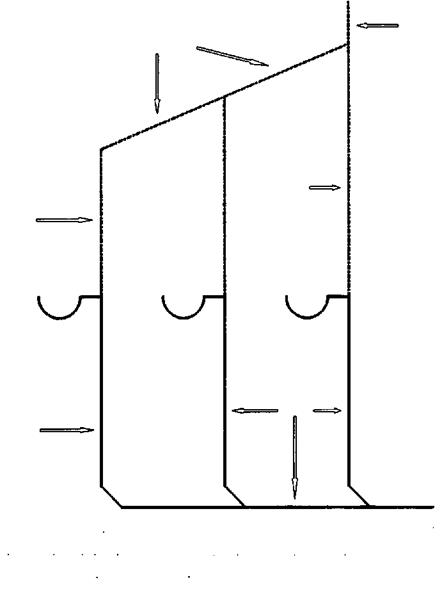
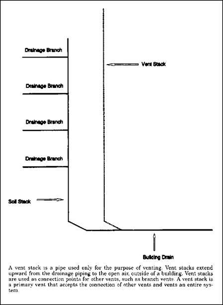
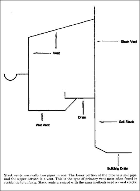
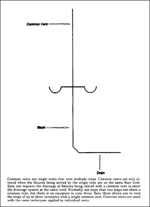
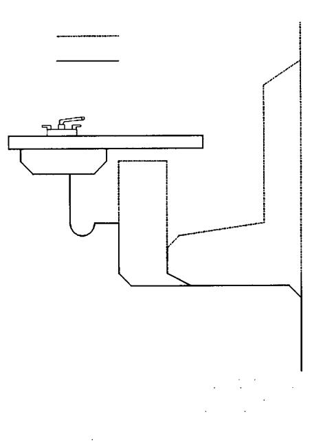
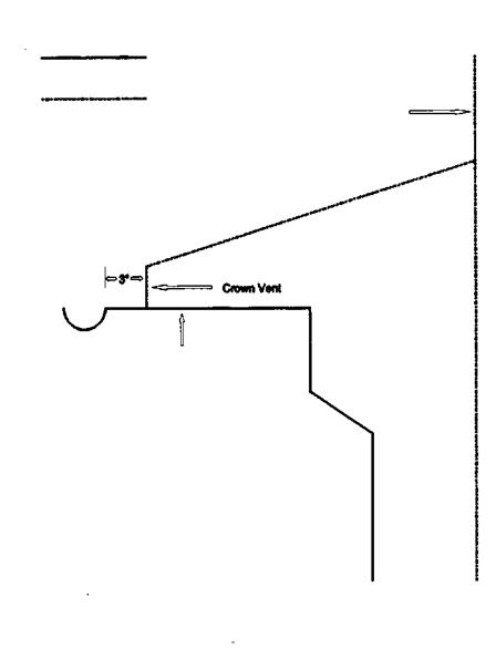
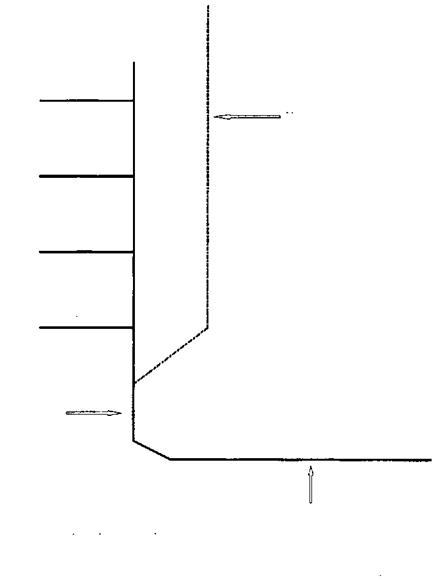
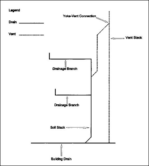
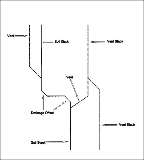
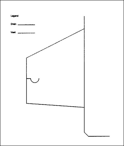
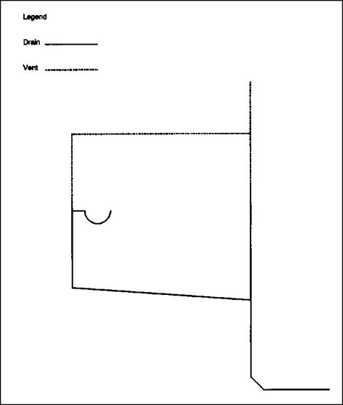
Types of vents are numerous. Do you know what an island vent is? How much do you know about relief vents? Depending upon your level of knowledge in the plumbing trade, you might be aware of all types of vents, but not all read­ers are. Before we jump into sizing examples, I’d like to make sure that all of my readers are aware of the various types of vents. With this in mind, I will provide a number of vent drawings for readers to devour. So, let’s get on with the visual examples of various vent types.

73

TYPES OF VENTS

TYPES OF VENTS

vent


Оси It Vert


Drain*


TYPES OF VENTS

TYPES OF VENTS

TYPES OF VENTS

Vert


Branch Vent


<=Vent


Vent


Drain


Drain


TYPES OF VENTS

TYPES OF VENTS

TYPES OF VENTS

TYPES OF VENTS

TYPES OF VENTS

TYPES OF VENTS

L*Qend


Vent


Drain


TYPES OF VENTS

TYPES OF VENTS

TYPES OF VENTS

TYPES OF VENTS

Legend


Drain


Vent


Vent Stack


11/2* Trap


Trap Ann


TYPES OF VENTS

TYPES OF VENTS

TYPES OF VENTS

Drainage Branch


vent Stack


Drainage Branch


Drainage Branch


Drainage Branch


Soil Stack


Building Drain


TYPES OF VENTS

TYPES OF VENTS

TYPES OF VENTS

TYPES OF VENTS

TYPES OF VENTS

TYPES OF VENTS

TYPES OF VENTS

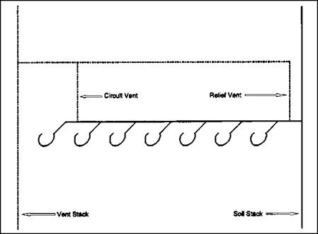
FIGURE 5.17 ■ Circuit vent with a relief vent. (Courtesy of McGraw-Hill)


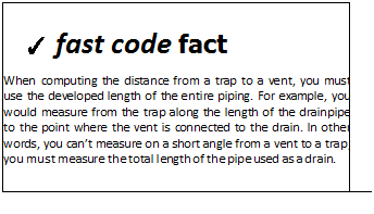
Подпись: When in doubt about if a vent is needed, install one. If you are not sure about the size of a vent, make it larger than what you believe is needed. For example, a toilet requires a vent with a minimum diameter of 2 inches. Most other residential fixtures can be vented with a pipe that has a diameter of 1.5 inches. All homes must have at least one 3-inch vent.Подпись: ✓ fast code fact When computing the distance from a trap to a vent, you must use the developed length of the entire piping. For example, you would measure from the trap along the length of the drainpipe to the point where the vent is connected to the drain. In other words, you can’t measure on a short angle from a vent to a trap; you must measure the total length of the pipe used as a drain.

► sensible shortcut