Repair and Replacement of Sign Panels

The decision on the appropriate action for damaged sign panels is a field judgment. Minor bending of a sign will prevent headlights from illuminating the sign at night. Signs with minor bends can be repaired by removing the sign from the post and straightening the sign. Signs that are badly bent cannot be properly repaired in the field. Attempts to straighten badly bent signs result in cracking and peeling of the sign face material. Many agencies consider it more economical to replace rather than repair signs that maintenance workers judge to be badly worn or damaged [46].

There are field repair kits available with pressure-sensitive reflective background sheeting and die-cut pressure-sensitive prespaced letters, borders, and symbols. It is often difficult, however, to properly apply these materials under field conditions. In addition to the difficulty of field repairs, a regulatory or warning sign should be placed on the post while repairs are being made. This sign may as well be a replace­ment sign and a more economical and durable repair made in the controlled environment of a shop operation. Do not take down a sign without immediately positioning a replacement. Extra signs should be placed in the service truck prior to leaving the garage. If field replacement of reflective sheeting is performed, however, the proper procedure provided by the manufacturer must be followed.

Finite Element Method

The basic idea of the finite element method is to divide the field to be analysed into sub-domains, the so-called finite elements, of simple shape: e. g. triangles, quadrilaterals with linear, parabolic or cubic sides for two-dimensional analysis. In each finite element, an analytically simple equation is postulated for the vari­able to be determined, i. e. the coordinate or displacement for solid mechanics, and the fluid pressure, temperature or concentration for diffusion problems. In order to obtain continuity, the unknown variable field has to be continuous at the limit between finite elements. This requirement is obtained thanks to common values of the field at specific points, the so-called nodes, which are linking the finite elements together. The field values at nodal points are the discretised problem unknowns.

For most solid mechanics and diffusion problems, isoparametric finite elements seem to be optimal (Zienkiewicz et al., 1988). The unknown field l (here represent­ing a set of displacements in all directions) may then be written, for solid mechanics cases1 as:

l = Nl g, n)xL L = 1, m (11.14)

where m is the number of nodes in the model. This unknown field, l_, then depends on the nodal unknowns xL (not only referring to the x – direction) and on shape functions Nl, which, themselves, depend on the isoparametric coordinates, f, n, defined on a reference, normalised, space. The strain rate and the spin may then be derived thanks to Eq. 11.5, the stress rate is obtained by Eqs. 11.3 and 11.4 and is time integrated. Eventually, equilibrium (Eq. 11.1) has to be checked.

For scalar diffusion or advection-diffusion problems, the unknown field, p, rep­resenting a general pressure (which could be pore pressure, u (the use here), tem­perature, T, or concentration, C, by appropriately changing the notation) may then be written:

p = Nl d, n) Pl L = 1, m (11.15)

Where p depends on the nodal unknowns, pL, and on the shape functions, Nl. Then Darcy’s fluid velocity and the storage changes may be derived thanks to Eqs. 11.7 and 11.8 (or, respectively, Eqs. 11.9 and 11.10). No time integration is required here. Finally, the balance equation (Eq. 11.6) has to be checked.

The finite element method allows an accurate modelling of the boundary con­dition, thanks to an easily adapted finite element shape. Internal boundaries of any shape between different geological layers or different solids can be modelled. Spe­cific finite elements for interfacial behaviour or for unilateral boundaries have also been developed (e. g. Charlier & Habraken, 1990). Variations of the finite element

size and density over the mesh are also easy to manage, with the help of modern mesh generators.

Bathtubs

Bathtubs for handicap use are required to have a seat. The seat may be built in or a detachable model. Grab bars with a minimum length of 24 inches must be mounted against the back wall, in line with each other and parallel to the floor. One of the bars, the top one, must be mounted a minimum of 33 inches and a maximum of 36 inches above the finished floor. The lower bar must be mounted 9 inches above the flood-level rim of the bathtub. A grab bar must be mounted at each end of the bathtub, with the bars being the same height as the top bar on the back wall. The bar used on the faucet end of the tub must be at least 24 inches long. A bar mounted at the other end of the tub must be at least 12 inches long. Faucets must be mounted below the grab bar. If a seat is installed at the end of a bathtub, the grab bar for that end must be omitted.

Showers

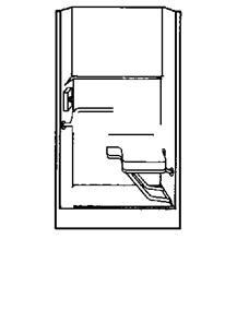
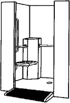
BathtubsThere are two basic types of showers for handicap use. Wide shower enclo­sures are one type, and square shower enclosures are the other. Shower stalls may be made on site or purchased as pre-fab units (Fig. 10.12). When a wide shower enclosure is used, it must have a minimum width of 60 inches. The depth must be no less than 30 inches. Thresholds are prohibited. Showers of this type must be made to allow wheelchairs to enter the enclosure. Shower valves must be mounted on the back wall. The minimum distance for the valve

Bathtubs

6950 RH Seat/6951 LH Seat Liberte

• Has fold-down seat. Placed at 18" height for easy transfer from wheelchair to seat.

• Two built-in soap shelves.

• One vertical and three horizontal grab bars.

• Inside diameter of 5′ for easy wheelchair turn inside stall

• Entry ramp 36" wide with gentle 8.3% grade.

• Lipped door ledge to prevent rolling out of stall.

• Anti-skid floor mat included.

• White.

• Optional dome (6951) available.


FIGURE 10.12 ■ Handicap shower with seat and ramp. (Courtesy of McGraw-Hill)

from the shower floor is 38 inches, with a maximum height of 48 inches. A grab bar must be mounted along the entire length of the three walls that form the enclosure. All grab bars are to be set at least 33 inches above the shower floor, but not more than 36 inches above the floor. And, the bars shall be mounted parallel to the shower floor.

Подпись: ► sensible shortcutBathtubsA shower enclosure that is square in design has to be at least 36 inches square.

Seats for this type of shower may have a seat with a maximum width of 16 inches.

Подпись: Don’t order handicap fixtures until you are sure that they are approved for use in your jurisdiction. When in doubt, check with your local code officer to confirm approval for specific fixtures.The seat must be mounted along the en­tire length of the shower. Seat height is established as a minimum of 17 inches above the shower floor, with a maximum height of 19 inches. Grab bars must be in­stalled to extend from the edge of the seat around the sidewall opposite the seat. These bars must be at least 33 inches above the shower floor, and not more than 36 inches above the floor. A shower valve must be mounted on the sidewall opposite the seat. The minimum height

of the shower valve shall be 38 inches above the floor. A maximum height of 48 inches is allowed for the installation of a shower valve.

Techniques to Reduce Vandalism

Techniques to reduce incidents of sign vandalism include steps that address the reasons

for vandalism, enable the prosecution of offenders, ease maintenance, and make it more

difficult to perform the vandalism. Consider the following to reduce vandalism:

• The theft and damage to many street name signs is due to the similarity to someone’s name. Vandalism to signs can often be reduced by adding St., Ave., or Blvd. to the sign.

• Use only standard signs. Signs that have an unusual message experience a higher vandalism rate.

• Use sign blank materials that are less susceptible to specific types of vandalism. Thicker-gage aluminum sign blanks can be used in areas that are subject to damage by bending. Plywood sign blanks are less susceptible to gunshots. Aluminum signs, when struck by gunshot, are indented over a /f-in-diameter (12.5-mm) circle per bullet hole, resulting in severe chipping and loss of reflectivity and legibility. Plywood signs remain legible even with numerous bullet holes. Plywood signs are also a less attractive target than aluminum signs, since they provide less noise and movement when used for target practice.

• Place an agency identification sticker on the back of each sign. This sticker should have a unique number for each sign, the agency name, whom to contact if the sign is found, and a warning about the legal consequences of stealing or damaging the sign. The identification sticker enables law enforcement officials to prosecute indi­viduals stealing or vandalizing the sign. The date of installation can also be placed on the sticker for maintenance information.

• Apply protective coatings to the sign face to ease the removal of foreign substances. Clear coatings, such as product number 711 or 731 from the 3M Company, can be applied by spraying, roll coating, or hand brushing. Transparent overlay films such as Scotchlite brand graphic overlay (GOF™) from the 3M Company are also available. The clear coat­ings and overlays allow the removal of crayon, paint, lipstick, and other contaminants with the use of strong solvents that would normally harm uncoated sign face material.

• Support twisting or removal can be reduced by installing approved supports of a heavier gauge and using anchor plates. Driven sign supports, as opposed to those installed by drilling and backfilling, are less susceptible to twisting.

• Use commercially available antitheft fasteners that make it difficult for vandals to remove signs. These fasteners include Tufnet, Teenut, aluminum fluted nuts, blind aluminum rivets, and Vandalgard nuts as illustrated in Figs. 7.54 through 7.56.

NEOPRENE

OR

NYLON WASHER

PLYWOOD SIGN

TUFNUTS’

t JUNCTION

NYLON WASHER

TYPICAL INSTALLATION PROCEDURE

STEP 1: INSTALL FIRST TUFNUT (N0.1) FINGER TIGHT AS SHOWN.

STEP 2: INSTALL SECOND TUFNUT (NO. 2) FINGER TIGHT AS SHOWN.

STEP 3: INSTALL WRENCH AT JUNCTION TO TIGHTEN (OR LOOSEN) AS NECESSARY

STEP 4: REMOVE TUFNUT NO. 2; THEN INSTALLATION IS COMPLETE.

SINGLE TUFNUT IS DIFFICULT TO REMOVE BECAUSE OF ITS SHAPE

ALWAYS USE FOUR TUFNUTS FOR EACH SIGN INSTALLATION.

TYPICAL TUFNUT (FOR 10 DIA CARRIAGE BOLT)

TYPICAL TUFNUT

(FOR 10 DIA CARRIAGE BOLT)

REMOVAL

FIGURE 7.55 Vandalgard sign fastener.

PLACE NYLON OR FIBER WASHER

BETWEEN SIGN FACE AND PALLET

WOOD POST SUPPORT (DIMENSION VARIABLE]

CARRIAGE BOLT JUST LONG

ENOUGH TO REACH POINT A

NYLON WASHER

IFOR WOOD POST SUPPORTS»

SPECIAL TOOL NO 2

МШ

ALUMINUM FLUTED NUT5 (FOR ALUMINUM DELINEATORS

AND SIGNS ON U – CHANNEL POSTS)

BLIND ALUMINUM RIVETS (FOR ALUMINUM AND 13

PLYWOOD SIGNS ON

U-CHANNEL POST9)

FIGURE 7.56 Teenut, aluminum fluted nut, and blind aluminum rivet sign fasteners.

7.8 MAINTENANCE OF TRAFFIC SIGNS

Continuing maintenance is required to ensure that traffic signs function for their intended purpose. Proper maintenance of all signs is important since the condition of the signs is a visual statement on the competency of the roadway agency. Regulatory and warning signs that are missing or in poor condition pose safety hazards to
motorists and can result in tort liability. Regulatory and warning signs must be repaired as soon as a defect is noticed. All of the signs on an agency’s roadway system should be inspected periodically to determine that their orientation and retroreflectivity properties are adequate for nighttime visibility.

Damage to traffic signs can occur as the result of environmental and wind load, accidents, improper installation, end of effective service life, and vandalism. Repairs can be required for the sign panel, the sign support, or both.

PREPARING FOR A JOB

The best way to make any project start smoothly is to adequately prepare for the job. This means spending time looking over the plans, and organizing information, and talking with whoever is overseeing the job before you start working on the job site.

Often, the lead framer does this preparation the night or morning before a job starts. You’ll find that the work will flow more smoothly if you begin preparation earlier and do it right.

If you’re a carpenter working for a framing contractor or a general contractor, many of the preparation tasks listed in this chapter will be done for you. If, on the other hand, you are the lead framer, framing contractor, and home builder all in one, then it’s up to you to get these done.

In this chapter, the word superintendent refers to the person on the job site who answers any questions related to the building. This person’s actual title might also be builder, owner, or framing contractor. Although this book is about house framing, we use the word building, since the preparation is very similar whether it is a house, multi-family housing, a commercial building, or any structure where wood framing is used.

If you are preparing to start the job with the foundation slab in place, you will need to perform these four tasks:

1. Develop a job start checklist.

2. Review the plans and make preparations.

3. Organize the job site.

4. Conduct the pre-start job site review meeting.

Developing a Job Start Checklist

Using a job start checklist is a good way to prepare. Your framing will be organized and will move at a steady pace if all the items on this list are addressed. You can fill out the checklist in a pre-start job site review meeting. While the pre­start visit is not absolutely required, it is a very productive part of the preparation.

Following is a blank Job Start Checklist that can be used at the job site review meeting. Along with the checklist is an explanation of some points to consider as you check off each item. Although the items may vary from job to job, most items on this list are common to all jobs. You should also add your own items to this list.


Job Start Checklist-Explanation

Consider as you check off the job start items.

1. Power Source

• Will you need more than one power source? Bigger jobs sometimes require more than one source.

• What length of extension cords will you need for power tools? A cord that’s too long can burn out your tools.

• Will you need a heavy lead cord?

• Is there enough voltage for your tools?

A compressor, for example, may require 220 volts.

2. Backfill

• Backfill all possible areas before you start. The more backfill completed, the easier it will be to perform your work.

3. Lumber Drop Location

• Ask for lumber to be dropped as close as possible to the building, and in a central location. If a forklift will be available, you can have the lumber dropped in a more out-of-the-way location, as long as it’s easily accessible.

• Often the lumber you need first is on the bottom of the lumber load when it is dropped. Sometimes you can request that the lumber company load the lumber in the order you will use it.

4. Material List

• Be sure you have a copy of the material takeoff list. This list will help you figure out which size, length, and grade of lumber will be used for which part of the building. It is a good check, and helps prevent mistakes.

5. Anchor Nuts and Washers

• The anchor nuts are generally delivered with the anchor bolts used by the foundation crew. Ask the superintendent to have the nuts located before you arrive on site, since trying to find them can be difficult.

6. Standard Framing Dimensions List

• Go over the list (shown later in this chapter) with the superintendent if applicable. He/she may need to check with the architect, or door or window manufacturer, in order to verify rough openings.

7. Plans: Two copies

• Be sure you have two copies of the plans. You will need one set for the job site. The second set can be used by others, such as the framing contractor, by yourself off site, or by the layout framer on bigger jobs.

8. Framing Hardware

• If you purchase the framing hardware yourself, you can have good control of quantities and delivery. If you don’t purchase it, request a hardware purchase list, which will help you identify quantities and type of hardware. It is common for the architect to specify a piece of hardware with a specific identifying number on it, then have the superintendent purchase

an equivalent piece of hardware with a different identifying number. It helps to carry a hardware manufacturer’s catalog with you for identification purposes. The Simpson Strong-Tie catalogs are most often referenced on plans.

9. Subfloor Glue

• Is subfloor glue required? It may not be called out on the plans or specifications, but sometimes superintendents require it.

10. Mudsill Insulation

• Determine whether mudsill insulation is necessary. Again, it may not be identified on the plans or specifications, but the job superintendent may intend to use it.

11. Hold-downs, Tie-downs, Anchoring System

• It is best to install the hold-down studs when the wall is built, and it is easiest to drill the holes for the hold-down bolts before the hold-down studs are nailed into the wall.

• Have at least one hold-down of each size on the job site when you start. Because the hold-down sizes vary, it’s good to have different sizes available so you can determine stud locations and bolt hole sizes and location. If you do not have the hold-downs, you can use a hardware catalog to determine hole sizes, locations, and stud locations.

12. Truss Plans and Delivery Schedule

• Many buildings have truss plans in addition to the plans provided by the architect. Because you want to line up the studs, floor joists, and roof trusses where possible, it is important to know where the truss manufacturer started the layout. You should use the truss layout and align the studs and floor joists. Truss plans typically call out where the layout starts.

• Often the truss plans are not drawn until shortly before they are needed. It is best to request the plans early so that they will be available when you need them.

• Check on the delivery date. Depending on the economy and the local truss manufacturers, the lead time for trusses can vary from days to weeks. You don’t want to get to the roof and have to stop because the trusses aren’t yet built.

13. Steel Plans and Delivery Schedule

• Typically if you have steel on the job, it should be in place before the wood framing is started. Check to see when it will be ready.

14. Reference Point for Finish Floor

• When you check the floor for level, it helps to have the benchmark used for the concrete work. If you don’t have the benchmark, then you have to take a number of different readings to come up with an average before you can determine whether the concrete work is within tolerance. Sometimes the superintendent will be able to give you the benchmark.

15. Reference Points for Wall Dimensions

• Having the reference points will save you time in determining where the lines are actually supposed to be. Since the concrete work is seldom exactly where it is supposed to be, you will have to decide by how much the concrete is off and the best way to compensate for it without doing extra work or compromising the building.

• If you don’t have reference points to work with, you will have to spend extra time taking measurements to determine where the mistakes are located in the concrete.

16. Location of Job Site Truck

• Be sure to locate your truck, trailer, or storage container close to the job site. Planning ahead with the superintendent can often open up a location that later could be occupied by other trades, material, or supplies.

Bath Water Found to be Culprit in Copper Toxicity Case

When F. W. was 63 years old she was seen by Dr. Elliott for a chronic vaginal discharge that had per­sisted for five years. She had been previously eval­uated by several healthcare practitioners for this problem. Although her gynecologist had been unable to find evidence of a yeast or bacterial in­fection, the patient was nevertheless placed on a variety of antibiotics, which seemed to exacerbate the problem.

During the interview, it was discovered that the patient’s symptoms seemed to improve when shetraveled. Shewentontodisclosethata rash she had all over her body also improved while she was away from home. She concluded that her symp­toms were probably related to stress, although there were no obvious new stressors in her life that could have accounted for this peculiar reaction.

When questioned about events in her life that took place around the time of onset of her symptoms, she revealed that she had moved into anew home. Dr. Elliott suspected that the source of the patient’s problem could be the bath water, since water was the only substance in contact with her vagina.

A water sample was sent to a laboratory for analysis. The results showed extremely high cop­per levels. Upon further inquiry, it was discovered that many water samples from the same part of town were also showing high copper levels. Ap­parently, the carbon dioxide in the water created enough of an acidic environment to dissolve the copper in the water supply piping.

The patient decided to install a whole-house water filtration system that could be customized to remove carbon dioxide in the household water.

system, consult the National Tap Water Qual­ity Database.3

Remember, however, that water leaving the treatment plant may be further contami­nated by the time it reaches your tap. During its journey, treated water can pick up lead from solder or old pipes and copper from pipes. Pipes made of PVC, the most common type of new piping, release chlorinated compounds and other chemicals into the water. Pipes that have breaks can suck in mud and silt and are prone to bacterial contamination.

Municipally treated water is usually low in biological contaminants because of chlorina­tion, but it is not well-screened for industrial and hazardous waste. The chlorine with which almost all municipal water has been treated often reacts with naturally occurring organic compounds, creating potentially harmful tri – halomethanes. Water experts in your area will know the range of contaminants found in your municipal system and the best strategies for eliminating them.

Private well-water quality is not governed by EPA regulations, but primary and second­ary standards for public systems are useful guidelines for the treatment of water in private wells. EPA recommends testing private water supplies annually for nitrates, coliform bacte­ria, total dissolved solids, and pH levels to de­tect contamination problems early. Your local water specialist should be able to make gen­eral recommendations for well-testing in your area.

Before consumption begins on a private water well, samples should be submitted for

Within a few days after installation, her rash and vaginitis disappeared. Because of evidence of ex­cess copper stored in her body, she underwent a program of vitamin and mineral supplementation and heavy metal chelation. She is currently doing well and is without complaints. In a follow-up visit, she stated that the greenish ring that had been present on the bathroom fixtures also had disap­peared.

Discussion

Copper is essential to human life, but in high doses can cause anemia, rashes, liver and kidney dam­age, and gastrointestinal irritation. While the need for filtering the household drinking water may be obvious, this case study illustrates that bath water may be an unrecognized source of toxic exposure.

Because the skin is a large surface area, it allows for significant absorption of substances into the body from bath water. We do not suggest that you avoid tub bathing, which can be both pleasurable and therapeutic. Instead, we recommend that your water be filtered at the point of entry into the house. Filtration systems are most effective when they are customized to fit both the home­owner’s personal needs and the local water condi­tions. These conditions can vary greatly from one location to another. Whether or not you decide to install a whole-house water filtration system, we recommend that you have your water tested periodically.

a comprehensive laboratory test by an EPA – approved laboratory. In addition to deter­mining what is in the well water, the test will help establish a baseline for future changes in water quality. Every well should be tested individually as even adjacent wells may have highly variable water chemistry because of different depths or geological variance of the aquifer.

SIGN VANDALISM PROBLEMS AND COUNTERMEASURES

Sign vandalism costs millions of dollars each year in increased maintenance costs and is a contributing cause to many accidents as well. In addition to the accident itself, van­dalized signs can expose the roadway agency and municipality to tort liability cases. Surveys of state and local agencies indicate that an average of 30 percent of all sign replacement and repair is due to vandalism and that an average of 30 percent of the sign maintenance budget is required for vandalized signs. Acts of sign vandalism are categorized as destruction, mutilation, and theft [16].

7.11.1 Destruction

Destruction occurs when the sign support or sign face is physically damaged to the extent that it no longer serves its intended purpose. Destruction vandalism includes damage from

• Gunshot

• Thrown projectiles such as rocks and bricks

• Sign bending

• Sign or support burning

• Deliberate sign or support knockdown

• Sign cutting with snips or saw

• Support twisting that results in improper orientation

• Support cutting

7.11.2 Mutilation

Sign mutilation occurs when the installation is altered or defaced in such a manner that the sign is illegible or loses its nighttime retroreflectivity characteristics. Examples of sign mutilation include

• Application of paint by spray or brush

• Application of unauthorized stickers or decals

• Contamination by caustic substances

• Alteration of sign legend by crayon, lipstick, or ink markers

• Reorientation of the sign panel

• Scratching the sign surface

• Peeling or removing reflective sheeting

7.11.3 Theft

Theft is the unauthorized removal of a sign assembly or any of its parts. Some common reasons for theft include

• Home decoration

• Relationship of the sign legend to an individual’s name or interests

• Construction or scrap value of the wood, aluminum, or metal parts

• Firewood

• Uniqueness of the sign legend

Creep Tests

Encouraging results of SMA resistance to deformation are being confirmed both in laboratory tests and on trial sections of pavements in operation. Clearly, in the majority of cases an SMA mixture is actually better than asphalt concrete (AC). Conversely, not every test method confirms that SMA possesses the better charac­teristics. The outcome depends on the loading mode and conditions of testing. The SMA tests resulting in divergent outcomes include

• Uniaxial creep test with a constant load (also called static creep), unconfined

• Uniaxial creep test with a repeated mode of loading (also called dynamic creep or repeated load axial test [RLAT]), unconfined

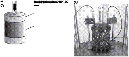
The classic versions of both tests have been carried out on 100 mm diameter speci­mens with a 100 mm loading platen (the so-called variant 100/100).

Figure 12.1 shows the mode of loading a 100 mm diameter cylindrical specimen with a 100 mm diameter platen. The whole top face of the cylinder is being loaded in an unconfined conditions (i. e., with no side support). Bearing in mind Figure 2.3, it is obvious that the power of an SMA structure also depends on the strength of the side support (Said et al., 2000). There is no such support in an unconfined creep test and loading the sample’s entire cross-sectional area. That is why, when testing SMA with this test, the results may suggest that SMA is a worse mixture than an AC mixture which has an aggregate mix characterized by a different type of particle interlocking. The fundamental assumptions of creep testing with no side support have been criticized for a long time (e. g., in Ulmgren, 1996). In spite of this, a large number of test results based on unconfined creep testing may be found in many publications.

The same tests with a different sample loading system produce different com­parative results between AC and SMA. The following are two other creep tests that incorporate side support:

• Uniaxial creep test with a repeated mode of load with side support (also called indentation repeated load axial test [IRLAT])—variant 100/150

• Uniaxial creep test with a repeated mode of load with vacuum confinement (also called vacuum repeated load axial test [VRLAT]; see also triaxial test).

image145

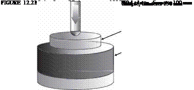
If a 100 mm diameter cylindrical specimen is replaced by a larger one (i. e., with one that has a 150 mm diameter [Figure 12.2]) and the loading plate has a diameter of 100 mm, then the loaded area of the specimen will be laterally supported. The

image147

FIGURE 12.1 Creep test with no side support, variant 100/100: (a) test scheme and (b) test­ing in Nottingham Asphalt Tester. (Photo courtesy of Krzysztof BlaZejowski.)

loading scheme (variant 100/150) and test results are, in this instance, closer to the real performance of a pavement on a road. In many countries, a modified creep test with a repeated mode of load (IRLAT or VRLAT) has been adopted for an assess­ment of the resistance to deformation of mixtures. Consequently, proper correlations between results of creep tests and wheel-tracking tests have been developed (Said et al., 2000; Ulmgren, 1996).

It is worth knowing that there is a substantial difference between the results of static creep tests of cylindrical specimens compacted in a laboratory for design pur­poses and specimens cut out of a finished course. Despite having the same composi­tion and similar densities, specimens cut out of a course are characterized by lower values of the creep modulus than Marshall and gyratory compacted specimens pre­pared in a laboratory (Renken, 2000).

According to the standard EN 13108-20, static and dynamic creep tests do not apply to SMA. The cyclical compression test (100/150—IRLAT) has been described in EN 12697-25 as method A, with test parameters as follows:

• Square loading pulse

• Frequency of 0.5 Hz (load 1 sec, rest period 1 sec)

• Load of 100 ± 2 kPa

• Typical test temperature of 40°C

• Total test duration of 3600 cycles (2 hours)

Latin hypercube sampling technique

The Latin hypercube sampling (LHS) technique is a special method under the umbrella of stratified sampling that selects random samples of each random variable over its range in a stratified manner. Consider a multiple integral involving K random variables

G = g (x) fx (x) d x = E [g (X)] (6.91)

J xeE

where X = (X1, X 2,…, XK )t is an K-dimensional vector of random variables, and fx(x) is their joint PDF.

The LHS technique divides the plausible range of each random variable into M(M > K in practice) equal-probability intervals. Within each interval, a single random variate is generated resulting in M random variates for each random variable. The expected value of g(X), then, is estimated as

1 M

G = g( X 1m, X 2m, …, XKm ) (6.92)

m=1

where Xkm is the variate generated for the kth random variable Xk in the mth set.

More specifically, consider a random variable Xk over the interval of [xk, xk ] following a specified PDF fk(xk). The range [xk, xk] is partitioned into M inter­vals, that is,

xk — xk0 < xk1 < xk2 < ”’ < xk, M—1 < xkM — xk (6.93)

in which P (xkm < Xk < xk, m+1) = 1/M for all m = 0, 1, 2,…, M — 1. The end points of the intervals are determined by solving

/

xkm m

fk (xk) dxk = m (6.94)

-k

where Fk ( ) is the CDF of the random variable Xk. The LHS technique, once the end points for all intervals are determined, randomly selects a single value

in each of the intervals to form the M samples set for Xk. The sample values can be obtained by the CDF-inverse or other appropriate method.

To generate M values of random variable Xk from each of the intervals, a sequence of probability values {pk1, pk2,…, pk, M-1, pkM} is generated as

m — 1

Pkm = M + Zkm m = 1,2,…, M (6.95)

in which {zk1, Zk2,…, Zk, M-1, ZkM} are independent uniform random numbers from Z ~ U(0, 1/M). After {pk1, pk2,…, pk, M-1, pkM} are generated, the corre­sponding M random samples for Xk can be determined as

Xkm = F-l( pkm) m = 1,2,…, M (6.96)

Note that pkm determined by Eq. (6.96) follows

pk1 < pk2 < ••• < pkm < ••• < pk, M-1 < pkM (6.97)

and accordingly,

xk1 — xk2 — — xkm — ‘ — xk, M-1 — xkM (6.98)

To make the generated {xk1, xk2,…, xk, M-1, xkM} a random sequence, random permutation can be applied to randomize the sequence. Alternatively, Latin hypercube samples for K random variables with size M can be generated by (Pebesma and Heuvelink, 1999), that is,

xkm = Fj-1^Skm MUkm ) (6.99)

where skm is a random permutation of 1 to M, and ukm is a uniformly distributed random variate in [0, 1]. Figure 6.14 shows the allocation of six samples by the LHS technique for a problem involving two random variables. It is seen that in each row or column of the 6 x 6 matrix only one cell contains a generated sample. The LHS algorithm can implemented as follows:

1. Select the number of subintervals M for each random variable, and divide the plausible range into M equal-probability intervals according to Eq. (6.94).

2. Generate M standard uniform random variates from U(0, 1/M).

3. Determine a sequence of probability values pkm, for k = 1, 2,…, K; m = 1,2,…, M, using Eq. (6.95).

4. Generate random variates for each of the random variables using an appro­priate method, such as Eq. (6.96).

5. Randomly permutate generated random sequences for all random variables.

6. Estimate G by Eq. (6.92).

Using the LHS technique, the usual estimators of G and its distribution function are unbiased (McKay, 1988). Moreover, when the function g(X) is

x21 x20

Подпись:Подпись: x24Подпись: X2 X23Подпись: x22Подпись:Latin hypercube sampling techniquemonotonic in each of the Xk, the variances of the estimators are no more than and often less than the variances when random variables are generated from simple random sampling. McKay (1988) suggested that the use of twice the number of involved random variables for sample size (M > 2K) would be suf­ficient to yield accurate estimation of the statistics model output. Iman and Helton (1985) indicated that a choice of M equal to 4/3K usually gives satisfac­tory results. For a dynamic stream water-quality model over a 1-year simula­tion period, Manache (2001) compared results from LHS using M = 4/3K and M = 3K and found reasonable convergence in the identification of the most sensitive parameters but not in calculation of the standard deviation of model output. Thus, if it is computationally feasible, the generation of a larger num­ber of samples would further enhance the accuracy of the estimation. Like all other variance-reduction Monte Carlo techniques, LHS generally would require fewer samples or model evaluations to achieve an accuracy level comparable with that obtained from a simple random sampling scheme. In hydrosystems engineering, the LHS technique has been applied widely to sediment transport (Yeh and Tung, 1993; Chang et al., 1993), water-quality modeling (Jaffe and Ferrara, 1984; Melching and Bauwens, 2001; Sohrabi et al., 2003; Manache and Melching, 2004), and rainfall-runoff modeling (Melching, 1995; Yu et al., 2001; Christiaens and Feyen, 2002; Lu and Tung, 2003).

Melching (1995) compared the results from LHS with M = 50 with those from Monte Carlo simulation with 10,000 simulations and also with those from FOVE and Rosenbleuth’s method for the case of using HEC-1 (U. S. Army Corps

of Engineers, 1991) to estimate flood peaks for a watershed in Illinois. All meth­ods yielded similar estimates of the mean value of the predicted peak flow. The variation of standard deviation estimates among the methods was much greater than that of the mean value estimates. In the estimation of the standard devia­tion of the peak flow, LHS was found to provide the closest agreement to Monte Carlo simulation, with an average error of 7.5 percent and 10 of 16 standard deviations within 10 percent of the value estimated with Monte Carlo simu­lation. This indicates that LHS can yield relatively accurate estimates of the mean and standard deviation of model output at a far smaller computational burden than Monte Carlo simulation. A detailed description of LHS, in con­junction with the regression analysis for uncertainty and sensitivity analysis, can be found elsewhere (Tung and Yen, 2005, Sec. 6.8).

Example 6.14 Referring to Example 6.7, apply the Latin hypercube sampling tech­nique to evaluate the pump failure probability in the time interval [0, 200 h].

Solution Again, the uniform distribution U(0, 200) is selected along with the sample- mean Monte Carlo method for carrying out the integration. In Latin hypercube sam­pling, the interval [0, 200] is divided into 1000 equal-probability subintervals, with each having a probability of 0.001. For U(0, 200), the end points of each subinterval can be obtained easily as

t0 = 0 t1 = °-2, t2 = °-4, ■ ■■ , £999 = 199.8, t1000 = 200

By the LHS, one random variate for each subinterval is generated. In other words, generate a single random variate from

Um ~ U[0.2(m — 1), 0.2m] m = 1, 2,…, 1000

The algorithm for estimating the pump failure probability involves the following steps:

1. Initialize the subinterval index m = 0.

2. Let m = m + 1. Generate one standard uniform random variate um, and transform

it into the random variate from the corresponding subinterval by tm = 0.2(m — 1) +

um.

3. If m < 1000, go to step 2; otherwise, compute the pump failure probability as

1 1000

pf = 1000 £ ft(tm)

m=1

and the associated standard deviation as

__ sm

Spf = V1000

with sm representing the standard deviation of 1000 computed function values

ft ™.

The results from the numerical simulation are

The 95 percent confidence interval is (0.14743, 0.14828). The value of pf is extremely close to the exact solution of 0.147856, and only 1000 simulations were used.

Numerical Tools: The Finite Element Method

11.2.1 Introduction

An approximated solution of most problems described by a set of partial differential equations may be obtained by numerical methods like the finite element method (FEM), the discrete element method (DEM), the finite difference method (FDM), the finite volume method (FVM), or the boundary element method (BEM). For the problems concerned here, the most commonly used methods are the finite element and the finite difference procedures. Commonly, non-linear solid mechanics is better solved using the finite element method. Boundary element methods have strong limitation in the non-linear field. Finite difference methods are not easy to apply to tensorial equations (with the exception of the FLAC code, developed by Itasca).

Diffusion and advection-diffusion problems are often solved by finite difference or finite element methods. Some finite difference (or finite volume) codes are very popular for fluid flow, like e. g. MODFLOW, TOUGH2 (Pruess et al., 1999) for aquifer modelling or ECLIPSE (Schlumberger 2000) for oil reservoir modelling. These codes have been developed over a number of years and possess a number of specific features allowing users to take numerous effects into account. However, they suffer from some drawbacks, which limit their potential for modelling coupled phenomena. Therefore only a little information will be included here concerning finite difference approaches.