Installing Posts

From the plan, we know that the posts should be six feet (1.8 meters) long. With the eight-by-ten girders on top of them, this gives six foot ten inches of clearance to the underside of the rafters at the lowest point. And it is seven foot eight inches to the ceiling, so there is a cozy, but not oppressive, feeling of space in the room. The rafter clearance is a few inches greater near the house.

Jaki and I were joined by family and interested friends for the remainder of the framing and roofing projects, including sons Darin and Rohan, Anna Milburn-Lauer, Bruce Kilgore, Diane Lukaris, and Stephanie Bayan. Work became fun with this rotating crew, a huge advantage.

I cut eight-by-eights with a chainsaw. The saw needs to be well sharpened, which means that it must not only cut easy, but also true, without pulling one way The very best way to assure straight cutting is to use a new bar and new chain. The next best way is to use a chain which has been professionally sharpened with a machine for the purpose. In any case, don’t make your first cut on an important short post. If you mess it up, the post may be rendered useless. Practice your technique on a long eight-by-eight, and keep cutting two inches (5.1 centimeters) off it until you can do a good job with regularity. Finally, when you’ve got a good square right-angled cut, and your confidence is high, measure, mark and cut the other end to length.

Bruce Kilgore made a wonderful cordwood cutoff saw, for use in making very regular log-ends for his house. He loaned me the saw, and I used it to cut quite a few of the heavy timbers for our sunroom frame. An explanation of how to make this saw is shown at pages 74—77 of my previous book Cordwood Building: The State of the Art (see Bibliography). A saw like this affords great control options. The swing of the saw can be fine-tuned to give a vertical cut every time. If need be, a shingle can be installed as a shim against the backrest of the table, giving another opportunity for fine angle adjustments. See pages 124—125.

No matter what method of cutting you choose, the cut may need to be dressed a little if it is still not square. Check it again with the large framing square and mark any high bits on the cut with a pencil. A little extra wood can be removed easily with a small Stanley Sure-Form™ Scraper, which has a 2- by 21/2-inch (5.1- by 6.3- centimeter) rasp on one end, and a handle that is used to pull the rasp towards you. You can put a lot of pressure on the wood with this tool, and it can remove wood very quickly. Another tool I use for the same purpose is my 5"-diameter Makita 4000-rpm circular sander, with #36-grit sanding disks for heavy wood removal, and #80 grit for finer work. Hint: very often, removing a high spot at the center of the new cut will stop a post from wobbling. Let the post bear on the edges.

Frequent use of the square and pencil is imperative, and becomes habitual after a while. With hand-hewn beams, or a timber with considerable wane on the edge, you may want to run a straightedge along the surface of the beam, and use your square off of the straightedge.

OIL-BASED VERSUS LATEX

Whether you’re painting exterior or interior sur­faces, latex paints are probably the best bet. The next sections explain why.

Two essential definitions.

► Oil-based paints and stains may contain linseed oil, tung oil, or synthetic resins called alkyds. Because alkyds are the most common "oil" in oil-based paints, professionals often use the term alkyd instead of oil-based. How­ever, oil-based is the broader, more inclusive term for products that must be thinned and cleaned up with solvents. Today only about 10 percent of house-paint sales are oil based.

► Latex paints and stains are water based and thus can be thinned with water and cleaned up with warm, soapy water. In recent

LANGUAGE: PRIMERS, PAINTS, AND STAINS

An important base coat, primer is applied to substrates such as raw wood, drywall, plaster, or previously painted surfaces. Above all, primers must stick to the substrate; they may also contain stain blockers, preservatives, pigments, or other additives to hide flaws and ensure more uniform top coats of paint.

► PAINT. If primer’s job is adhesion, paint’s is protection-protecting the primer and substrate from moisture, mild abuse, and (if it’s exterior paint) UV rays. Paint must also hold color, dry smoothly, and withstand weather, so its pig­ments, solvents, and additives must be carefully blended and held together by a binder, or resin.

► BINDER. Binders determine a paint’s pene­tration, adhesion, drying rate, flexibility, and durability. In relation to pigment, the more binder a paint has, the shinier and more durable its finish will be. Glossy paints tend to have high binder-to-pigment ratios.

► PIGMENT. Color is determined by pigment. The more pigment a paint has, the more intense its color and the better it hides what’s beneath.

► VEHICLE. A paint’s liquid component, the vehicle, is needed to suspend the pigments and binders. Oil-based vehicles (linseed oil, tung oil, or modified oils called alkyds) thin with mineral spirits, also known as paint thinner. Latex paints suspend polymer particles (plastic) in water.

► STAIN. Penetrating or semitransparent stains are most often pigmented oils that soak into wood and form a thin film on the wood’s surface; there are also water-based stains. You can see wood grain through stain. Although stains may contain water repellants, preservatives, and some UV blocking, they don’t protect wood as well as paint does and so must be reapplied periodically-say, every 2 years to 4 years.

► S0LID-C0l.0R STAIN. solid-color stain, a fast-growing group of exterior coatings, is more like thinned paint than stain. It’s popular because wood texture (but not wood grain) remains visible. However, solid-color stains have only about half the life span of painted surfaces. Acrylic latex solid-color stains are the most durable.

decades, latex paints have improved so dra­matically that they now account for about 90 percent of house-paint sales.

Oil-based: Advantages and disadvantages.

Oil-based paints are durable and tenacious, adhering even to glossy or chalky surfaces. Thus many pros still insist on an oil-based exterior primer, even if they’ll be applying latex top coats. Many old-school painters also favor oil-based paints for interior trim, because they dry slowly and level well, thus minimizing brush marks.

Problem is, oil-based paints never completely cure. Rather, they oxidize and, over the years, erode and crack. Any siding, especially wood, expands and contracts as temperatures fluctuate, so the inflexibility of oil-based paints leads to cracking and more commonly chalking, a pow­dery residue of oxidized oil and pigment. In addi­tion, mold feeds on the organic compounds in oil-based paints. But the biggest problem is their solvents: noxious, volatile, polluting, and tedious to clean off tools and equipment.

Latex: Advantages and disadvantages. Acrylic latex has almost everything a painter or a sub­strate could want: As the paint or stain dries, its water base evaporates with minimal odor, leaving a thin coat of polymer particles (plastic) that remains flexible and so rarely cracks, as oil-based paints often do. Latex is also semipermeable, so moisture generated inside the house can migrate, through the paint, to the outdoors. Because latex is synthetic, it’s inhospitable to mold. Finally, latex cleans up easily and dries quickly.

Inside, latex is the only paint to use on dry – wall, for it won’t raise the paper surface of panels.

Clear FINISHES

Clear finishes include polyurethane, varnish, lacquer, and shellac. Polyurethane, also called poly, is the most durable of the clear finishes and thus the most suitable for heavy-traffic surfaces, such as trim and stair parts. Although poly and varnish resist moisture, they may become cloudy with sustained exposure to wet conditions. Shellac also clouds up near water. Spar varnish—originally used on boats—has a hard finish that stands up well to water, if well maintained. For more about clear floor finishes, see Chapter 20.

Exterior latex is colorfast, durable, and easy to apply. However, its quick drying characteristic can be a problem if you’re painting an exterior in 90° heat, which causes the paint to dry on the brush. In that case, additives like Flood’s Floetrol® will slow drying time and so extend latex’s “brushability.”

Bau-Biology Standard SBM 2008: A Unique Indoor Environmental Assessment Tool

The professional Bau-Biology Standard SBM 2008 provides a uniqueand comprehensiveassessment and evaluation system consisting of over30 indoor environmental parameters. The Standard uses an unorthodox approach because it is not based on single threshold limit values derived from medical dose responses. Instead, the Standard uses a gra­dient scale with four different levels based on the concentration levels normally encountered in na­
ture or non-problem buildings. The evaluation cri­teria are determined by the deviations from this normal state and are expressed as categories of change. The categories are: normal environment, slight change, significant change, and severe change. The table below defines the four catego­ries used in the Standard and provides an example for carbon dioxide (C02) levels.

Normal Environment

Slight Change

Significant Change

Severe Change

Reflects normal envi­ronmental conditions or common and inevitable background levels in our civilized environment

Slightly higher levels; fol­lowing the precautionary principle, long-term miti­gation is recommended, especially with sensitive or ill individuals

Likely to present an elevated risk; short-term mitigation is recom­mended

Call for immediate action and mitigation; in many cases interna­tional guidelines for occupational exposure limits may be reached or exceeded

C02 <500 ppm

C02 500-700 ppm

C02 700-1000 ppm

C02 >1000 ppm

The Bau-Biology Standard is based on the pre­cautionary principle. It is derived from studies based on long-term exposure during the human regeneration phase (while sleeping) and was es­tablished over decades of experience. The refer­ence values are designed for sleeping areas, not for commercial or industrial workplaces. All other standards in North America are based on the work­place and do not directly address health at home. The Bau-Biology Standard itself is divided into two sections: Evaluation Guidelines and StandardTest­ing Methodology. These are further differentiated into three groups of environmental parameters:

• Group A. Indoor Air Climate and Environmen­tal Toxins

___________________________________________________________________

• Group B. Fungi, Bacteria, and Allergens

• Group C. Physical Fields and Radiation

A comprehensive assessment of potential biologi­cal environmental risk factors and their reduction to achievable levels are the basis of the Standard.

The Institute for Bau-Biology and Ecology (IBN) was founded in 1976 by Anton Schneider of Ger­many. The German word "Bau" means building, habitat, or shelter. "Biology" refers to the study of living things. The institute studies and addresses the impact buildings have on human health and promotes healthy, environmentally and ecologi­cally friendly construction techniques.

The Standard was developed between 1987 and 1992 by the consulting firm of Baubiologie

Maes in conjunction with the IBN, environmental consultants, physicians, and scientists. The docu­ment was initially published in the German jour­nal Wohnung und Gesundheit (Living Spaces and Health) in 1992. A ten-member Standard Commit­tee reviews and revises the document periodically. The latest update was in 2003. In the meantime, the Standard has been internationally accepted as a comprehensive tool for independent indoor environmental assessments in Europe, Australia, and New Zealand and is available in the United States through the International Institute for Bau – Biologie & Ecology in Clearwater, Florida.

The three groups of environmental param­eters and categories of change are outlined in a condensed version in the following tables. The Baubiology Evaluation Guidelines are proposed for sleeping areas and are not directly related to work areas.

Group A: Indoor Air Climate and Environmental Toxins

A

Parameter

Normal

environment

Slight change

Significant

change

Severe change

1

Carbon dioxide concentration in air (ppm)

600

600-1000

1000-1500

>1500

2

Relative humidity (%)

40-60

<40 / >60

<30/>70

<20/>80

3

Formaldehyde concentration in air (ppm)

0.02

0.02-0.05

0.05-0.1

>0.1

4

Total volatile organic compounds in air (pg/m3)

<100

100-300

300-1000

>1000

5

Total pesticides concentration in air (ng/m3)

<1

5-25

25-100

>100

6

PCP, lindane, permethrin in wood (mg/kg)

<1

1-10

10-100

>100

7

Dichlofluanid, chlorpyrifos in dust (mg/kg)

<0.5

0.5-2

2-10

>10

8

PCBs, chlorinated fire retardants in dust (mg/kg)

<0.5

0.5-2

2-10

>10

9

Polyaromatic hydrocarbons in dust (mg/kg)

<0.5

0.5-2

2-20

>20

10

Plasticizer in dust (mg/kg)

<100

100-250

250-1000

>1000

11

Small air ions (per cm3)

>500

200-500

100-200

<100

12

Electrostatic charge in air (V/m)

<100

100-500

500-2,000

>2,000

Group В: Fungi, Bacteria, and Allergens

В

Mold counts (spore counts or colony forming units)

1. Mold counts should be less or similar when compared to sur­rounding outdoor environments or non-problem buildings.

II. Mold types in the indoor air should be similar to those present in the outside air.

III. Particular toxic species such as Aspergillus or Stachybotrys, yeast-like fungi such as Candida or Cryptococcus, and coliform bacteria should be present only in low concentration levels.

IV. Any suspected microbial colonization (water damage, odors, material deterioration, high RH, or building history) should be investigated.

Group C: Physical Fields and Radiation

C

Parameter

Normal

environment

Slight

change

Significant

change

Severe

change

1

AC electric fields in air (V/m)

<1

1 -5

5-50

>50

2

AC electric fields on body (mV)

<10

10-100

100-1000

>1000

3

AC magnetic fields, flux density (mG)

<0.2

0.2-1

1-5

>5

4

Microwaves in power density (uW/m2)

<0.1

0.1-10

10-100

>100

5

DC electrostatic charge, surface (V)

<100

100-500

500-2,000

>2,000

6

DC electrostatic charge, discharge time (s)

<10

10-30

30-60

>60

7

DC magnetic fields, deviation (ЦТ)

<1

1-2

2-10

>10

8

DC Magnetic fields, deviation (degree)

<2

2-10

10-100

>100

9

Ionizing radiation (increase in %)

<50

50-70

70-100

>100

10

Radon gas in air (Bq/m3)

<30

30-60

60-200

>200

11

Terrestrial radiation, deviation (nT)

<100

100-200

200-1,000

>1000

12

Terrestrial radiation, deviation (%)

<10

10-20

20-50

>50

The Standard Testing Methodology for these environmental parameters was developed in con­junction with the Evaluation Guidelines to provide consistent and repeatable measurement results. Bau-Biology building investigations and assess­ments are unique because they examine a large number of environmental factors and look to na­ture, our planet Earth, for guiding principles.

The Standard makes a quantum leap by ab­andoning the traditional dose response-based threshold and action levels. It provides informa­tion on normally encountered background levels and establishes gradients that enable the envi­ronmental consultant to put measurement values into a real-life, proactive perspective.

Most indoor environmental testing in the United States focuses on a very few factors such as mold, asbestos, formaldehyde, and lead. Rarely does it address the electromagnetic spectrum, which has changed so significantly over the last decades. The knowledge of how to test, assess, evaluate, and heal our habitats and structures em­powers us to improve our health, safety, and well­being in a lasting way.

For a copy of the actual standards or more in­formation on testing, assessment, and Bau-Biology concepts, contact the author or the institutes and associations listed below:

• Peter Sierck, President, Environmental Testing &Technology, Inc., 5431 Avenida Encinas, Suite F, Carlsbad, CA 92008,760-804-9400, PSierck@ ETandT. com, Baubiology. com

• I nstitut fur Baubiologie&Okologie Neubeuern IBN, baubiologie. de

• International Institute for Bau-Biologie & Ecol­ogy (IBE), Clearwater, Florida, buildingbiology. net

* Berufsverbad Deutscher Baubiologen (VDB), baubiologie. net

• Verband Baubiologie, verband-baubiologie. de

Peter Sierck, CMC, CMRS, REA, BBEI, founder of En – vironmentalTesting andTechnology, Inc. (ET&T) in 1986, pioneered indoor air quality testing meth­ods and procedures for residential and commer­cial buildings. Peter is a naturopathic physician, industrial hygienist, and Bau-Biologist. He has surveyed and helped remediate over 3,000 build­ings and is a member of the Bau-Biology Standard Committee.

or glass slide and ship it to the laboratory. The lab technicians will stain the tape sample to make the fungal growth easier to view and then examine it under a microscope.

Different Types of Management

There are many ways to manage framers. It is important to know the different management styles and the effects that they have on employees, so that you can create the most productive framing crew. There are three main styles of management: autocratic, bureaucratic, and democratic.

Autocratic: The lead framer has the decision­making power and does not delegate authority.

Discussion and suggestions are generally not permitted. This style sometimes motivates framers to please the lead framer instead of to improve productivity. It also discourages framers from finding creative solutions.

Bureaucratic: The lead framer enforces established rules, regulations, policies, and procedures to run the crew. This style does not allow for creative The autocratic lead framer

solutions.

Democratic: Framers help determine the goals of the company. The lead framer organizes and directs the framers as part of his job as a crew member. If a problem comes up between the lead framer and a framer, they work together to find a solution they can both accept. This style usually creates a congenial work atmosphere.

Most lead framers use a combination of the three styles. This lets them have authority when they need it, while getting the help from their framers in developing the most productive methods for accomplishing their work.

Managing a framing crew can be compared to playing quarterback on a football team. Your team has to have confidence in your ability to direct them. The team expects you to tell them when they make mistakes, but they also expect you to tell them what they need to know to do a good job and to be considerate of them. In effect, you have to develop a working relationship with each framer.

Different Types of Framing Crews

There are different types of framing crews, which require some adjustment in style. They are:

1. Hourly employees

2. Piece workers

3. A combination of the two

Hourly workers are paid by the hour. Their goal is to keep their employer happy with their work. They typically are more concerned with quality of work than with speed. Piece workers are paid by the amount of work they finish. Their main goal is to get as much work as possible done within a certain time frame. A combination of the two allows for the employee to be paid for each hour he or she works, then to receive a bonus for completing extra work within a defined time frame. A combination system can provide the motivation to maintain speed, while still allowing you a great degree of control over the job.

More on Motivation

Motivation is the intangible factor that can make or break a crew, and probably the single most important factor that affects framers, yet it is not something you can demand of your crew. As a lead framer, you want to support individual framers and maintain a high level of motivation in the crew.

Ideas for Building Relationships and Motivation

1. Honesty is a basic. A framer will observe not only what you say and how you treat him or her, but what you say to others and how you treat them. Keep your framers well-informed. If there is a slow-down coming up, and some framers might be laid off, let them know. You risk the chance of them quitting before the job is finished, but if you want them to be on your side, you have to be on theirs.

2. The first day on a job is the most important time for setting a new framer’s attitude toward his or her job. Take time to introduce him to the whole crew and show him where he can

find tools, the first aid kit, and portable toilets. Allow time for him to acclimate to the job.

3. Developing relationships takes time and a conscious effort. While your time is valuable, and you have to balance it, try to listen to what your framers have to say, and show patience. If you want them to support your interests, you have to be concerned about theirs. Make yourself available and easy to talk to. Encourage open and free resolution of problems, and make every effort to use your framers’ suggestions, or explain why if you decide not to. This gives the framers positive feedback and gets them thinking about better and faster ways to accomplish tasks. If you constantly reject their suggestions, you reduce their motivation.

4. Use power discreetly. The more you have to display authority, the less valuable it becomes. Persuasion and guidance can be more effective than a show of authority.

5. Assign more responsibility and train framers to take on new tasks whenever the job allows. This will motivate framers to take on more duties.

6. Teach framers how to solve problems.

7. Praise framers for good work. This helps create a positive attitude, especially when it is done publicly. Compliments are a good relationship-builder, especially when framers first start working with you. Go out of your way to find something they have done well. Hopefully you can get a couple of positive compliments in before you have to start pointing out any mistakes.

8. Expect some mistakes and use them as learning opportunities. Making mistakes and learning on the job are everyday occurrences and should not create fear in a framer. Your framers need to know that you are there to teach and direct them, and that you will be fair and reasonable.

9. Make criticism into a learning experience and give it in private. When a framer makes mistakes or is sloppy, don’t assume it’s intentional. Calmly explain what he did wrong. Direct the criticism at the action, not the person. Be specific. For example, “your nails are not sunk deep enough," instead of, “you are a horrible nailer." If the framer does not improve or change, then you may have to tell him that he is not suited for the work and should look for work elsewhere.

10. Pitch in and be a good example, especially if the job is one that nobody wants to do. You should not feel that any task is beneath you.

11. Be courteous. Everybody likes to hear “please" and “thank you." Saying “thank you" is a good way to finish up without giving the workers the sense that they are dismissed.

Respecting your framers will help keep them motivated, and help get the job done right.

Competition as a Motivator

It is sometimes possible to create competition that will provide enjoyment for your framers and increase productivity. Here is an example:

A while ago, I had a couple of hammers left over from tools I had purchased for a training class. On the job, we were framing a two-story hotel with two long walls on either side. I woke up one morning asking myself,"How can I make these walls go quicker?" I decided to create a competition by splitting the four framers into two teams, with one team on each side of the hotel. The winning team— the one that got their wall up first—would get the hammers. With the competition, the framers enjoyed the day and got a lot more wall framed than normal. Healthy competitions can help provide motivation.

Goals

One of the best management tools is goal-setting.

It develops motivation by creating a reason to work productively, gives you a tool for judging the productivity of a framer, and provides a benchmark for discussing each framer’s daily tasks. Goals should be set for different time periods, ranging from the entire length of the job, to daily or task goals. Goals can be written down, or you can go over them in a conversation with your framers.

Goals for the job are usually defined in the beginning by your schedule and manpower.

It helps to break down your overall project goals into goals for each part of the job, like the first – floor walls, the joists, and the rafters. Once you know the goals for the major parts of the job, you can begin to set your daily goals.

Set daily goals the first thing in the morning. You might want to think about them and who you will assign to each task on your way to work. After assigning the tasks, ask each individual to set their own goals for the day, which you can review with them.

Framers sometimes think they can get more work done in a day than they actually can. In this case, all you have to do is agree with their goals, and encourage your framers to achieve them. If, on the other hand, they set their goals at a lower rate of productivity than you expect, review their goals with them, and see if you can teach them faster ways to achieve them. You might do a little of their work for them so they can see how fast it is supposed to be done.

If you can’t agree on a goal with a framer, give him another task, and assign his original task to someone else. At the end of the day you can compare how much work the other person accomplished with what you and the first framer expected, then determine which one of you was more on-target. This takes time and effort on your part, but sometimes that’s what’s needed to create motivation—which will save time in the long run.

It’s important to review goals when your framers are done with their tasks—either at the end of the day or the next morning before you set new goals. This will show framers that goals are important. It

also lets you determine when and if improvement is necessary. Set goals that are realistic and obtainable, but still challenging.

When setting goals, consider the learning curve. Studies have found that when you double the amount of similar work that someone does, their productivity increases by 20%. Even experienced framers have a learning curve.

The more experience you have, the clearer your goals will be. The more you set goals, the better you will become at it.

Painting

Подпись: Sometimes art doesn't hang on a wall: It is the wall.

Painting is probably the most popular reno­vation task because its effects are immediate and striking. For not much money or effort, you can get a complete change of scenery and heart. If you own a few basic tools, your costs will be lim­ited to the few tools you’ll need to rent and the paint you choose.

This chapter covers both exterior and interior painting, including trim, doors, windows, and cabinets. For information on stripping and fin­ishing floors, refer to Chapter 20.

Essential Prep Work

If you want painted surfaces to look good and last long, the substrate—such as drywall, plaster, and wood—must be stable and dry before you start. Thus prep work (preparing surfaces) is crucial for a good paint job, vital advice that recurs in this chapter. Whether you’ll be painting a building’s interior or exterior, follow these guidelines:

► Correct structural or moisture-related problems.

► Scrape or sand down paint that’s poorly adhered or applied excessively.

► Sand surface irregularities.

► Choose primer that will adhere well and be compatible with the finish coats.

► Follow instructions on paint containers.

► Sand lightly between coats for better adhesion.

Choosing Paint

Manufacturers frequently reformulate their primers, paints, and stains, so look for a repu­table supplier who keeps up with changes. Before buying paint, examine the surfaces to be painted and think about the conditions it must endure. Then ask the following questions.

FOUR TELLING QUESTIONS

► Interior or exterior paint? Beware of any container labeled "interior/exterior.” It’s probably cheap. Quality exterior paints contain additives that repel moisture, block UV rays, and discourage mold. These additives are not substances you’d want to inhale indoors while the paint is curing. Thus never use exterior paints indoors and vice versa.

► Has the surface been painted before? Surfaces should be primed if they (1) have never been painted, (2) have been extensively scraped or sanded, or (3) are "chalky” or poorly prepped. However, if existing paint is

Подпись:Подпись: PROnP Buy the best paint and equipment you can afford. Good paint adheres better, dries smoother, and lasts longer. Generally, quality paint has higher percentages of solids (pigments and binders) that yield a thicker film of paint when dry. Using cheap paint is a waste of time and money. 1111 Подпись: ColorfulПодпись:well adhered, priming isn’t necessary; just paint over the old coat.

► What type of finish (sheen) do you want? Top-coat finishes range from flat (also called dull or matte) to semigloss (a. k.a. eggshell, velvet, satin) to gloss. Glossier finishes tend to be more durable and easier to clean, so they’re favored on doors and windows, on trim, and in high-use areas such as bathrooms and kitchens. Enamel, which dries to a hard, durable finish, is best for window sashes, doors, and casings.

► Is the surface unusual? There are spe­cialty paints for masonry; for hard, nonporous surfaces such as tile and glass; for often-damp areas; and for nonslip surfaces. There are even paints for acoustical tile that don’t reduce the tile’s sound-deadening properties. Check with your supplier.

Asthma from a Chlorinated Swimming Pool

When B. W. was a five-year-old boy he came with his parents to consult with Dr. Elliott about his asthma. The most recent flare-up had occurred during a school field trip to the local swim­ming pool. Upon further questioning, a pattern emerged revealing a relationship between water and the triggering of the child’s asthma. Dr. Elliott suspected that the chlorine in the water was act­ing as an irritant to his airways. She suggested that thefamily swim in a public pool that had switched to ozone for water purification. In that particular pool, chlorine was used as a supplement, but only in very small quantities. They were happy to note that their son could now swim comfortably with his friends without difficulty breathing. The family went on to purchase filters for their showerheads that effectively removed chlorine from their show­ers. They also removed all chlorinated cleaning products from their home. Now that there was

• adequate mechanical ventilation and de­humidification

• a watertight enclosure around the pool area that retards vapor diffusion to prevent water damage to the surrounding struc­ture

• surface finishes that are impervious to water and easily cleaned

• a rigorous maintenance program to re­move condensation and mold growth as soon as they appear

Because of the intensive upkeep required to maintain a pool or spa so that it does not neg­atively impact indoor air quality, we do not readily recommend including an enclosed body of water inside a healthy home. How – one less triggering agent for the asthma, Dr. Elliott could more effectively focus on strengthening the boy’s lungs.

Discussion

Chlorine is a poison used to kill bacteria in water. It is absorbed through the skin, inhaled into the lungs, and ingested. At room temperature, chlo­rine is a gas with a pungent smell. It is very reac­tive, combining readily with most elements to form compounds, many of which, such as chloro­form, trihalomethanes, and organochiorines, are known to be carcinogenic. Symptoms commonly resulting from swimming in chlorinated water in­clude runny nose, red eyes, cough, asthma, joint pains, swelling, nausea, urinary discomfort, rashes, and hives. We suggest that you use a less toxic dis­infectant for your pool.

ever, if an indoor pool is planned for the home, consider taking advantage of the large body of heated water as part of the design for a com­prehensive climate control strategy. The water can act as a reservoir for solar heat storage and humidification.

Environmental Testing

It may be desirable to conduct diverse quality control tests or product analysis while select­ing materials and throughout the construc­tion process. This testing can help ensure that materials and installations are as specified. Planning in advance for many of these tests is recommended. Waiting until the last minute will result in costly construction delays since many of these procedures will require that you order test kits, hire specialists, or wait for labo­ratory results.

Materials Testing

In choosing healthy materials, you and your architect will base decisions on information supplied by the manufacturer, such as prod­uct literature and an MSDS, as well as on the appearance and smell of the products. While certain hazardous substances, such as lead, asbestos, mercury, and polychlorinated bi­phenyls (PCBs), are no longer a concern for products manufactured in North America, precautions may be required if you are using recycled or imported materials. Available tests are included in Chart 13.1. Materials tests you may want to consider are discussed below.

pH Testing for Concrete Slabs

Concrete must be properly cured to ensure its strength and durability. Improperly cured concrete may exhibit a strongly alkaline pH, which can cause adverse chemical reactions when certain adhesives and flooring materi­als come into contact with the concrete. The pH of cured concrete must be under 9 to be considered acceptable. A pH test is performed by dampening an area of concrete with dis­tilled or deionized water. The dampened area is then tested with pH paper or with a special pH test pencil available from the Sinak Cor­poration. The color change that the paper or pencil mark indicates is the pH level.

Formaldehyde Testing

Although many manufacturers are now us­ing less formaldehyde than they once were, it is still a common additive in many products. The cumulative effect of several products con­taining only moderate amounts of formalde­hyde can cause severe health consequences. Our approach is to avoid this chemical when­ever formaldehyde-free substitutes can be lo­cated.

A simple do-it-yourself spot test can be used to ensure that products containing form­aldehyde are not used. A drop of test solution is placed on the material in question and al­lowed to stand for two minutes. If the drop changes from clear to purple, formaldehyde or other harmful aldehydes are present. The shade of purple can range from a faint pink to a dark plum, depending on the concentration of aldehydes. The test must be read at exactly two minutes because the drop will eventually turn purple even if no aldehydes are present. The solution leaves a purple stain on porous materials and should be used in a place where will not be visible.

Surface Sampling for Fungus

Materials damaged by mold growth should be rejected, but not all stains are from mold. Lab­oratory analysis will probably be required to determine if mold is a problem, but there are several do-it-yourself methods for collecting mold samples.

Bulk Sampling

Collect a small amount of the material in ques­tion in a doubled plastic bag and send it to the laboratory. A teaspoonful of the suspected material is probably enough.

Tape Sampling

Press a piece of clear cellophane tape onto the surface to be tested. The best place for sampling is at the edge between the stained area and the dean area. Then stick the tape to a plastic bag

The destiny of Shi Huangdi, first emperor

The eulogy of Shi Huangdi (formerly Zheng) is engraved on the gates of the city of Jishi. It recognizes not only his destiny as a conquerer, but also his contributions to hydraulic infrastructure:

“He took down the inner and outer fortifications,

“He opened the watercourses and erected dikes,

“He leveled the dangerous gorges.”[405]

His overall influence was clearly civilizing, and he put into place the administrative structures that made the unification of China inevitable. He is harshly treated by Chinese historians, however. Indeed, in a conflict with the scholars in 213 BC he massacres a number of them and burns their writings.

Shi Huangdi’s famous army of 6,000 men in terra-cotta is buried in his monumen­tal tomb near his capital Xianyang, about thirty kilometers from the present-day Xi’an, discovered in 1974. A marvelous testimony to the hydraulic developments of Qin is the reproduction of the land’s rivers on a scale model in his honor, using mercury as the fluid subject to a flow control system:[406]

“In the ninth month, Shi Huangdi was buried in the Li mountain. [….] With mercury, the hun­dred watercourses were made, the Kiang, the Ho, and the vast sea; machines made the mercu­ry flow and transferred it from one to the other. Above were all the signs of the heavens; below all the geographic details. [….] Those who were put to death were very numerous.”[407]

Design Methodology for MSE Walls

Figure 8.32 shows the general design equations given by AASHTO for MSE walls with a horizontal backslope and a traffic surcharge. Included is the calculation of safety factors for overturning and sliding, and the maximum base pressure. Inclusion of a traffic sur­charge is required only in those instances where traffic loadings will actually surcharge the wall. Separate surcharge diagrams are applied for the two conditions shown. For sta­bility of the mass, the traffic surcharge should act at the end of the reinforced zone so as to eliminate the “stabilizing” effect of this loading. However, for purposes of determining horizontal stresses, which are increased as a result of this surcharge, the loading is

Assumed for bearing capacity and overall (global) stability comps.

Assumed for overturning and sliding resistance comps.

FACTOR OF SAFETY AGAINST OVERTURNING (MOMENTS ABOUT POINT 0):

= S moments resisting (Mr) = V1 (L/2) 2 0

OT moments overturning (Mo) F1 (H/3) + F2 (H/2) _ .

FACTOR OF SAFETY AGAINST SLIDING:

Fs = S horizontal resisting force(s) = V1 (tan p or tan ф)* ___ 15 SL horizontal driving force(s) F1 + F2 _ ‘

ф = friction angle of reinforced backfill or foundation, whichever is lowest

where q = traffic live load

*tan p is for continuous soil reinforcement (e. g., grids and sheets).

For discontinuous soil reinforcements (e. g., strips) use tan ф. p is the soil/ reinforcement interface friction angle. Use the lower of tan at the base of the wall or tan p at the lowest reinforcement layer for continuous reinforcements.

Note: For relatively thick facing elements (e. g., segmental concrete facing blocks), it may be desirable to include the facing dimensions and weight in sliding and overturning calculations (i. e., use B in lieu of L).

FIGURE 8.32 General design requirements for MSE walls with horizontal backfill and traffic surcharge. (From Standard Specifications for Highway Bridges, American Association of State Highway and Transportation Officials, Washington, D. C., 2002, with permission)

deemed to apply over the entire surface of the wall backfill. Figure 8.33a and b shows the AASHTO equations for the sloping backfill case and the broken backfill case.

While the conventional analysis of a mechanically stabilized earth wall assumes a rigid body, field evaluation has shown that the variation and magnitude of the foundation loading exerted by the wall on the underlying soil differ from the traditional trapezoidal

FACTOR OF SAFETY AGAINST OVERTURNING (MOMENTS ABOUT POINT 0):

Fg = X moments resisting (Mr) = V1 (L/2) + V2 (2L/3) + Fv (L) ^ ^

OT moments overturning (Mo) FH (h/3)

FACTOR OF SAFETY AGAINST SLIDING:

Fs = X horizontal resisting force(s) (V1 + V2 + Fv) (tan p or tan ф)*^

SL horizontal driving force(s) FH _ ‘

ф = friction angle of reinforced backfill or foundation, whichever is lowest

*tan p is for continuous soil reinforcements (e. g., grids and sheets).

For discontinuous soil reinforcements (e. g., strips) use tan ф. p is the soil/ reinforcement interface friction angle. Use the lower of tan at the base of the wall or tan p at the lowest reinforcement layer for continuous reinforcements.

Note: For relatively thick facing elements (e. g., segmental concrete facing blocks), it may be desirable to include the facing dimensions and weight in sliding and overturning calculations (i. e., use B in lieu of L).

FIGURE 8.33a General design requirements for MSE walls with sloping backfill.

(From Standard Specifications for Highway Bridges, 2002, American Association of State Highway and Transportation Officials, Washington, D. C., with permission)

Fv = Ft cos ( I )

For infinite slope I = p Ka for retained fill using 8 = p = I: sin2 (0 + ф’)

FACTOR OF SAFETY AGAINST OVERTURNING (MOMENTS ABOUT POINT 0): Fg 2 moments resisting (Mr) = V1 (L/2) + V2 (2L/3) + Fv (L) ^ 20

OT moments overturning (Mo) Fh (h/3)

FACTOR OF SAFETY AGAINST SLIDING:

Fs £ horizontal resisting force(s) = (V1 + V2 + Fv) (tan p or tan Ф)*^ 1 5 SL horizontal driving force(s) Fh _ ‘

ф = friction angle of reinforced backfill or foundation, whichever is lowest

*tan p is for continuous soil reinforcements (e. g., grids and sheets).

For discontinuous soil reinforcements (e. g., strips) use tan ф. p is the soil/ reinforcement interface friction angle. Use the lower of tan ф at the base of the wall or tan p at the lowest reinforcement layer for continuous reinforcements.

Note: For relatively thick facing elements (e. g., segmental concrete facing blocks), it may be desirable to include the facing dimensions and weight in sliding and overturning calculations (i. e., use B in lieu of L).

FIGURE 8.33b General requirements for MSE walls with broken backfill.

(From Standard Specifications for Highway Bridges, 2002, American Association of State Highway Officials, Washington, D. C., with permission)

pressure distribution assumed under reinforced-concrete cantilever walls. Tests were per­formed by placing pressure cells under the base of an MSE wall. The wall was the Fremersdorf wall constructed in Germany, which is depicted in Fig. 8.34 along with the bearing pressure recorded from the pressure cells. Tests on that structure demonstrated that loading is greater toward the front of the structure because of earth pressure imposed

FIGURE 8.34 Fremersdorf MSE wall with foundation pressures from pressure cell readings. (From the Reinforced Earth Co., with permission)

by the retained fill behind the wall. In addition, the total load was slightly greater than the total weight of the wall, indicating that the thrust behind the structure was inclined. The difference between total loading and weight, and the location of the resultant, made it possible to compute the thrust angle p.

The bearing pressure distribution from the Fremersdorf wall is idealized in the AASHTO equation for soil pressure (cv) shown in Fig. 8.35. A uniform pressure (Meyerhof distribution) is calculated over a width equal to the length of the soil rein­forcement elements minus 2 times the eccentricity of the vertical force.

Reinforced Fill Materials

Well-graded, free-draining granular material is usually specified for permanent-placed soil reinforced walls. Lower-quality materials are sometimes used in reinforced embank­ment slopes. Experience with cohesive backfills is limited. However, low strength, creep properties, and poor drainage characteristics make their use undesirable. Some current research is focused on the use of cohesive soil backfills.

The following gradation and plasticity limits have been established by the AASHTO-AGC-ARTBA* Joint Committee Task Force 27 for mechanically stabilized embankments:

U. S. sieve size

Percent passing

4 in (100 mm)

100

No. 40

0-60

No. 200

0-15

Plasticity index (PI) less than 6 percent

It it recommended that the maximum particle size be limited to /4 in (19 mm) for geosynthetics and epoxy-coated reinforcements unless tests show that there is minimal construction damage if larger particle sizes are used.

Metallurgical slag or cinders should not be used except as specifically allowed by the designer. Material should be furnished that exhibits an angle of internal friction of 34° or more, as determined by AASHTO T-236, on the portion finer than the No. 10 sieve. The backfill material should be compacted to 95 percent of AASHTO T-99, method C or D, at optimum moisture content. See Art. 8.5.7 for backfill requirements that are important in relation to the durability of the steel reinforcement.

On-site or local material of marginal quality can be used only with the discretion and approval of the designer.

FALSE BEAMS

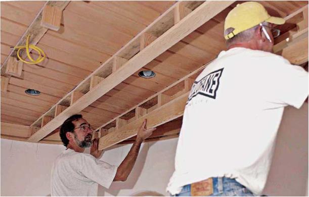
There are several ways to construct false beams. Two are shown here. The first is to make a ladder frame (imagine a ladder set horizontally) clad with finish boards. This type, shown below, runs perpendicular to ceiling joists so its top board can be screwed to them; end-nail "ladder rungs” to the top board before installing it. Once the top board is secured to joists, attach the bottom board and then the sides. A power nailer is a must because the assembly is shaky till all the boards are on.

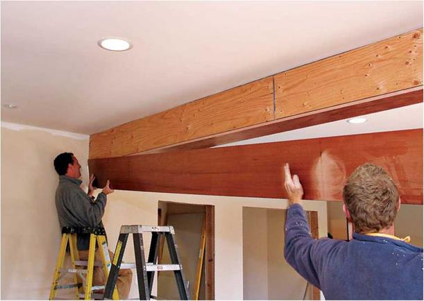
The second type, shown in the photos on the facing page, is more correctly called a box beam because there’s nothing false about the steel I-beam it’s disguising. You can order I-beams with bolt holes predrilled, making it easy to bolt plywood nailing blocks to them. The plywood shown was faced with clear fir on three sides and
stained to simulate redwood. Because the under­side of the box was most visible at eye level, the carpenters took pains to create an even reveal along the bottom of the beam. The gaps along the top of the beam were later covered by the crown molding shown in the top photo on p. 429.

WAINSCOTING

In the old days, when raised-panel wainscoting was constructed from solid wood, fancy joinery was required to accommodate the expansion and contraction of the panels. Today, thanks to the stability of MDF panels and readily available stock molding, you can create good-looking wainscoting with simple joinery (see p. 432). Once painted, this new wainscoting will be almost indistinguishable from that built with traditional materials and methods.

Construct the frame rails (horizontal pieces) and stiles (vertical pieces) from clear, straight 1 x4s; if you need more than one board to attain the length you need, use a biscuit joiner (see the

FALSE BEAMS

image888

Scan left to right on the ceiling, and you’ll see the evolution of a false beam. Preassemble the top board (which nails to the ceiling joists) and short nailer blocks. Install the bottom board, then the sides. Use a pneumatic nailer only, for hand nailing will loosen the assembly.


image889
BOXING IN A STEEL I-BEAM

To provide nailing surfaces for the sides of the box beam, first bolt plywood strips to the predrilled I-beam. Attach the bottom panel of the box beam first, then the sides.

image890Because the underside is the most visible part of the box beam from eye level, measure to be sure the board reveals are consistent. Measuring also tells you exactly where the edge of the bottom board is—so nails don’t miss it. Cover gaps along the ceiling with crown molding.
bottom photo on p. 407) to splice the board ends. Use this tool to strengthen the butt joints between rails and stiles, too. But first, snap chalklines onto the walls to indicate the position of rails and stiles; if any stiles coincide with elec­trical outlets, it may be easiest to relocate the outlets so that all the panels along a wall have a consistent width.

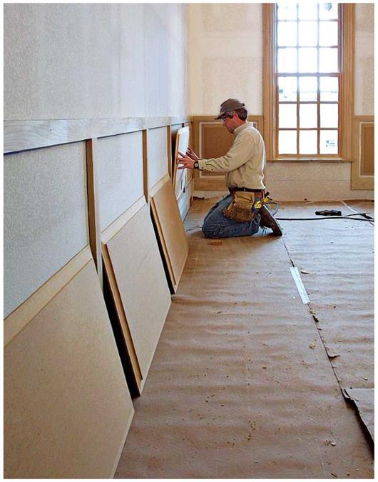
Assemble the frame on the floor. After allow­ing its glued and biscuited joints to cure, tilt the frame upright, and screw it to wall studs, using 15-gauge finish nails. To avoid stressing the frame joints, have a helper tilt it up and hold it atop spacer blocks as you nail it. The 54-in. MDF
panels are best routed in several passes to avoid frying the router and scorching the panel edges. Once you’re done routing, sand the panel edges lightly and nail them to the wall, leaving an even gap all around, between panel edges and frame elements.

Although you can use any type of stock mold­ing to cover the gaps around the panels, a shaped molding adds visual interest and has a traditional feel—bolection molding has a nice profile and a rabbeted back edge that seats neatly against frame edges. Cap the top of the top rail with molding too, to cover the slight gap between the frame and the wall.

After screwing the preassembled frame to the studs, insert shaped MDF panels, nailing them directly to the wall with 2-in. brads. Leave a 1-in. gap around each panel, which you’ll cover with stock molding.


image891